Ronan Engineering X96S Instructions And Operating Manual
Density gauge
Hide thumbs
Also See for X96S:
- Instructions and operating manual (68 pages) ,
- Instructions and operating manual (77 pages) ,
- Instructions and operating manual (57 pages)
Table of Contents
Advertisement
Instructions
and
Operating Manual
X96S
DENSITY GAUGE
60%
Ronan Engineering
Process Setup
Filtering
Low Alarm
High Alarm
Empty Clamp
Linearization
Temp.
Press.
RONAN ENGINEERING COMPANY – MEASUREMENTS DIVISION
8050 Production Drive
Florence, KY 41042
Phone: (859) 342‐8500
Fax: (859) 342‐6426
Website: www.ronan.com
E‐mail: ronan@ronanmeasure.com
Advertisement
Table of Contents

Related Manuals for Ronan Engineering X96S


Summary of Contents for Ronan Engineering X96S
- Page 1 Instructions Operating Manual X96S DENSITY GAUGE Ronan Engineering Process Setup Filtering Low Alarm High Alarm Empty Clamp Linearization Temp. Press. RONAN ENGINEERING COMPANY – MEASUREMENTS DIVISION 8050 Production Drive Florence, KY 41042 Phone: (859) 342‐8500 Fax: (859) 342‐6426 Website: www.ronan.com E‐mail: ronan@ronanmeasure.com ...
-
Page 2: Table Of Contents
Table of Contents For the latest updates go to www.ronanmeasure.com Overview ................................... 1 Advantages ..................................1 Gamma's Advantages ..............................1 X96S Advantages ................................1 Basic Concepts .................................. 2 Communications ................................2 4-20 MA ..................................2 HART .................................... 2 Variables ................................... 2 Communications Variables ............................ - Page 3 Pressure Reference Menu ............................. 29 Loop Config Menu ..............................29 Aux Loop Cfg Menu ..............................30 Diagnostics................................... 30 X96S Local Display ................................ 31 Navigating Menus ................................31 Editing Values ................................32 Editing Fixed Point Numbers ............................32 Editing Floating Point Numbers ..........................32 Editing Text Strings ..............................
-
Page 4: Overview
Overview The X96S is a family of measurement products that is intended to replace the current X99 and obsolete X96N product families. These products: use nuclear measurement techniques, support all features of the current X99 and obsolete X96N products, ... -
Page 5: Basic Concepts
SV is assigned to an optional secondary 4-20 mA loop. Device Variables The Ronan X96S Density gauge has several device variables: SGU, % solids weight, degree Twad, degree Brix, degree Baum hv, degree Baum lt, degree API, degree Ball, % steam quality, 5 acids. -
Page 6: Theory
These different representations of the density value are called D1 and The X96S displays the output measurement range in the selected user units. Channel 1 and Channel 2 can be set independently. For both channels, the "zero"... -
Page 7: Principles Of Operation
The Calibration (or Referencing) procedure relates detector output (in counts) to numeric values that accurately represent the actual process density. The density algorithm (or curve) used by the X96S software is a logarithmic function. That is, the relationship between the detector output and the process density is mathematically expressed as:... -
Page 8: Password
Password Notice: To access the Programming Menu, the Password is 101010. Step 1: Power Up – You should now be on the Status Screen. Step 2: Press F3 to go back. Step 3: Now enter the password. (All digits are set at 000000 at this point.) Press to get the digit to be # one Press... -
Page 9: Menus/Operation
Menus/Operation Menu Trees The Ronan X96S Density Gauge uses a tree structured menu system. Ronan X96S - Density Variables Variables Status Display Configuration Variable Mapping Variable Mapping Digital Outputs PV [value units] Digital Inputs SV [value units] PV is [var mapped to PV]... - Page 10 Configuration Operation Operation D1 Config D2 Config Filtering Filtering Proc Temp Config Empty Clamp Pressure Config Detector Fault Type Head Temp Config Linearization Dyn Track [enable/disable] Alarms Temp Comp Sigma [value] Hardware Pressure Comp Fast TC [seconds] HART Scan Time [ms] Fast Counter [value] System Medium TC [seconds]...
- Page 11 Proc Temp [variable] Slot 1 Details Source Type Slot 2 Pressure [variable] Slot 2 Details Analog Out Config Slot 3 HART Output X96S-20 Slot 3 Details Com1 Protocol Ronan Slot 4 Slot 4 Details Slot 5 Slot 5 Details Slot 6...
- Page 12 Power Source [int/ext] Tag Name [S.O. No.] HART Output Multi Drop [number] Univ Rev [read only] Spec Rev [read only] None X96S-2005 System Ser. Port 1 Serial # [read only] Com1 Protocol Hardware Rev [read only] Software Rev [read only]...
- Page 13 Digital Outputs Output [select] Output Relay 1 Select Sources Relay 2 Polarity Relay 3 Relay 4 TTL 1 TTL 2 TTL 3 TTL 4 Select Sources Output [type] Output Alarm 1 [yes/no] [select] Alarm 2 [yes/no] Relay 1 Alarm 3 [yes/no] Relay 2 Alarm 4 [yes/no] Relay 3...
- Page 14 Calibration State [status] Ref Constants Ref Constants Calibrate Last Ref Date [date] Ref Mode [variable] Last Ref Time [time] Calibr. Mode [variable] Loop Config Ref Time [seconds] Aux Loop Cfg Min Ref Cnts [counts] Max Ref Cnts [counts] Calibrate Low Reference Low Reference Perform Reference High Calibrate...
- Page 15 Calibration Loop Config State [status] Ref Constants PV is [variable] PV/SV/TV Calibrate Loop test [Select] Last Ref Date [date] Damping [number] Last Ref Time [time] D/A trim Loop Config Aux Loop Cfg Aux Loop Config Proc Temp Pressure SV is [variable] Head Temp Aux 1 Test Not Assigned...
-
Page 16: Root Menu
Root Menu The root menu is titled “Ronan X96S – Density”. It contains the following items: ITEM FUNCTION Variables Selecting this takes the user to the Variables menu. Status Display Selecting this takes the user to the Displays menu. Configuration Selecting this takes the user to the Configuration menu. -
Page 17: Status Display Menu
Status Display Menu The menu titled “Status Display” is used to configure the device status display. It contains the following items ITEM FUNCTION Analog Bar Shows the current state of the analog bar display (enabled or disabled) and allows the user change the state. -
Page 18: Operation Menu
Operation Menu The Operation menu is used to access the menus and variables that control the processing of the density data. It contains the following items: ITEM FUNCTION Filtering Selecting this takes the user to the Filtering menu. Empty Clamp Selecting this takes the user to the Empty Clamp menu. -
Page 19: Empty Clamp Menu
Empty Clamp Menu The X96S uses a mechanism called empty clamp to protect detectors (particular scintillation detectors) from saturation conditions. I.e.: The pipe is typically full, but where the pipe goes empty, therefore causing too much radiation to reach the detector, possibly damaging the electronics. -
Page 20: Linearization Menu
Referencing function. Process temperature is typically read via platinum or nickel, 2 or 3-wire RTD attached to the X96S. In these cases, the X96S needs no temperature calibration. -
Page 21: Pressure Comp Menu
Temp Units is one of the following: ITEM MEANING degC degrees Celsius degF degrees Fahrenheit degR degrees Rankine Kelvin degrees Kelvin Pressure Comp Menu Pressure compensation is calculated based on the pressure input. The pressure-input range is selected in the Configuration Menu, Pressure Config Menu. -
Page 22: D1 Config Menu
D1 Config Menu The D1 Config menu is used to configure the parameters associated with the density measurement. It contains the following items: ITEM FUNCTION D1 Units Shows and allows the user to set the density units used D1 Low Range Shows and allows the user to set the density value to be mapped to 4ma on the current loop output, if D1 is selected to control that current loop. -
Page 23: D2 Config Menu
D2 Config Menu The D2 Config menu is used to configure the parameters associated with the alternate representation of the density measurement. It contains the following items: ITEM FUNCTION D2 Units Shows and allows the user to set the density units used for the alternate representation of the density measurement D2 Low Range Shows and allows the user to set the density value to be mapped to 4ma on the current... -
Page 24: Proc Temp Config Menu
Proc Temp Config Menu The Proc Temp Config menu is used to configure the parameters associated with the process temperature measurement. It contains the following items: ITEM FUNCTION Temp Units Shows and allows the user to set the units to be used for process temperature Low Range Shows and allows the user to set the temperature value to be mapped to 4ma on the current loop output, if process temperature is selected to control that current loop. -
Page 25: Head Temp Config Menu
Head Temp Config Menu The Head Temp Config menu is used to configure the parameters associated with the detector electronics temperature measurement. It contains the following items: ITEM FUNCTION Temp Units Shows and allows the user to set the units to be used for head temperature Low Range Shows and allows the user to set the temperature value to be mapped to 4ma on the current loop output, if head temperature is selected to control that current loop. -
Page 26: Hardware Menu
Hardware Menu The Hardware menu is used to define the type of hardware used to provide measurements and radiation. It contains the following items: ITEM FUNCTION System Hardware Shows the user the list of hardware modules in the system and the status of these modules. -
Page 27: Source Type Menu
FUNCTION X96S-2005 Selecting this will assign the HART card to the desired loop X96S-2004, chan 1 Selecting this will assign the Analog out card to channel 1. X96S-2004, chan 2 Selecting this will assign the Analog out card to channel 2. -
Page 28: Hart Menu
Shows the HART universal command revision to which this device is conferment Spec Rev Shows the HART specification revision to which this device is conferment. System Menu The System menu is used to provide information about the X96S. It contains the following items: ITEM FUNCTION Serial #... -
Page 29: Digital Outputs Menu
Relay and TTL Menus The Relay and TTL menus are used to configure the X96S Relay Outputs and the 4 TTL Outputs. The Relay and TTL menus show the settings of the corresponding 4 Relay Outputs and 4 TTL Outputs, allowing the characteristics of the outputs to be changed. Each... -
Page 30: Digital Inputs Menu
A “true” is represented by a low signal on the digital input High A “true” is represented by a high signal on the digital input Calibration Menu This menu is used to view and control the calibration of the X96S Density Gauge. It contains the following items: ITEM FUNCTION State... -
Page 31: 8050 Production Drive
Ref Constants Menu This menu is used to view and control the reference constants used in the reference and calibration procedures. It contains the following items: ITEM FUNCTION Ref Mode Shows and allows the user to set the Reference Mode. Calib. -
Page 32: Manual Entry
Manual Entry This menu is used to perform the manual entry of the 1/uT (multiplier). Temp Reference Menu (This menu is ONLY used if the Hardware Menu, Proc Temp value is set for 0-10 volts or 4-20 ma.) This menu is used to perform the process temperature reference procedure. It contains the following items: ITEM FUNCTION Temp LoRef... -
Page 33: Aux Loop Cfg Menu
Diagnostics ITEM FUNCTION Raw Counts Non-filtered counts from the detector Filt Counts X96S filtered counts from the detector Raw Dens. Displays the real time raw density value Current Displays the real time 4-20ma value Ref/Cal Data Displays the information on the reference/calibration data... -
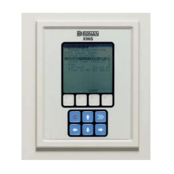
Page 34: X96S Local Display
X96S Local Display X96S 30% Ronan Engineering X96S Density Gauge The X96S Local Display consists of 8 lines by 21-character Menu Title display and a 10 key keypad. The top line of the display is Analog Bar Menu line 1 reserved for the analog bar, if enabled. -
Page 35: Editing Values
Editing Values The editing of different types of values is designed around the use of the four direction keys and up to 4 function keys. The left and right arrow keys are used to position the cursor to the letter/digit to be edited, and up and down arrow keys are used to scroll between the possible values for this position. -
Page 36: Installation
Installation Ronan's Density Gauge uses a sealed radioactive Caution cesium (Cs-137 ) or cobalt (CO-60) source which is safe if handled properly. Specific License If your gauge is equipped with the SA or GS series source holder, you are required to obtain a specific license. Your (SA or GS Series) company's specific license will name a Radiation Safety Officer (RSO) or Radiation Protection Officer (RPO). - Page 37 The source holder is equipped with an ON/OFF INSPECTION Mechanism. During shipment and storage the mechanism MUST BE SECURED in the OFF position with a padlock. Radiation Label If the padlock is damaged, broken, or missing, contact the RSO immediately. General License Label (if applicable) Handle Padlocked OFF...
- Page 38 Radiation Label General License (If applicable) Rod Padlocked OFF General License Radiation Label RLL1 or 2 Lock Tag WARNING THIS DEVICE MAY BE MOUNTED IN PLACE INITIALLY BY ANY PERSON PROVIDED THE SHUTTER REMAINS LOCKED IN THE OFF POSITION. ONLY A SPECIFICALLY LICENSED PERSON MAY PLACE THE DEVICE IN SERVICE BY INITIALLY OPENING THE SHUTTER AND MAKING THE REQUIRED LEAK TEST, TESTING FOR PROPER...
-
Page 39: Safety Precautions
Safety Precautions During installation the RSO will provide guidelines to assure safety. Consider the information presented in the Regulation/Safety Chapter of this manual, as well as the following general guidelines: The source holder must remain padlocked in the OFF position until installation is complete. -
Page 40: Mechanical Mounting
Mechanical Mounting Review the Configuration Drawing, which is included in the Drawing Chapter of this manual. Please reference the dimensional drawings located in the Drawing Chapter of this manual when installing the equipment. Drawings Consider the following general guidelines when mounting the sensor and detector: Avoid internal vessel obstructions such as baffles, agitators, man-ways, heater/cooler tubes, etc. -
Page 41: Location For Ronan Density Gauge
Location for Ronan Density Gauge The ideal location for the Ronan Density gauge is where there is no entrained air, the process is well mixed, the flow has a uniformed cross-sectional area, the flow direction is upward and where a representative sample of the process can be accessed. -
Page 42: Electrical Installation Of Interconnect Wiring
Electrical Installation of Interconnect Wiring DO NOT APPLY POWER until wiring is carefully checked. Wire the equipment according to the detailed interconnect drawing which is included in the drawing section of your packet. Drawings Follow local and national electrical codes for all interconnections. -
Page 43: Microprocessor Verification
Options: 1 Input Board 2 Input Boards Identification/ The Ronan X96S Microprocessor can be programmed for a Documentation variety of applications and configurations. The specific application supplied with each system is determined by the combination of software and the unique hardware configuration used to support the software. -
Page 44: Power-Up
Power-up X96S Before applying power, ensure all boards are fully seated in frame’s slots. Close front door of the X96S and secure the door... Ronan Engineering When power is applied the X96S runs a self-diagnostic Please, wait…. program. First display appears for just a second. -
Page 45: Password
Password Notice: To access the Programming Menu, the Password is 101010. Step 1: Power Up – You should now be on the Status Screen. Step 2: Press F3 to go back. Step 3: Now enter the password. (All digits are set at 000000 at this point.) Press to get the digit to be # one Press... -
Page 46: Quick Start Reference - Calibrating Density
Quick Start Reference – Calibrating Density What type of calibration is needed? Two types of calibration are available for Ronan’s density gauge. Single-point calibration This requires an accurate laboratory analysis of a truly representative sample of one process density. Single-Point Calibration is used as an alternative method when it is not physically or economically practical to vary the process density. - Page 47 Quick Start Reference – Calibrating Density Ronan Engineering X96S Density Gauge Step 1 Start at the Status Display Status Display 12.1860 % sol-wt 1.1860 SGU From the Status Display Screen, Press the F3 Key to display the Proc Temp 50.00 deg...
- Page 48 Scroll down to “Calibration” Press to enter menu Ronan Engineering Scroll down to “Calibrate” Press the to enter menu X96S Density Gauge Scroll down to “Low Reference” Press the to enter menu Main Menu Variables Select “Reference”...
- Page 49 Scroll down to “Manual Entry” Press to enter menu Select “1/uT” press to enter menu Ronan Engineering Notice a value is displayed. X96S Density Gauge Main Menu Variables The transmission constant can be manually calculated and entered...
- Page 50 Step 4 ‘High Density’ Calibration (Have the process ready in the calibrate condition) Ronan Engineering X96S Density Gage Scroll down to “Calibration” Press to enter menu Main Menu Scroll down to “Calibrate” Press to enter menu...
-
Page 51: Calibration
This initial reference sample can be any process density in the range of interest. The conveniently drawn process sample is analyzed in the lab so the known density value can be entered into the X96S as the reference density (d Next, the manually calculated calibration constant (1/ut) value, from a table like the one below, is entered into the X96S software. -
Page 52: Calibration Constant
The first curve below shows the relationship for a single-point calibration between the Low Reference, the Calibration constant, and the X96S output value. The calibration curve below depicts a two-point calibration and the relationship between the Low Reference, High Calibrate, and the X96S output value. -
Page 53: High Calibration (Dual Point Calibration)
The calibration procedure also reverses the relationship between detector counts and actual process density. Now, a direct relationship exists, so that as the process density changes from light to heavy, the X96S's display screen indicates an increase in user units from minimum to maximum - (example: 1.1 SpG to 1.25 SpG.) -
Page 54: Single-Point Calibration Procedure
Single-Point Calibration Procedure As an alternative, the single-point calibration can be used. In that case, the results of the first sampling procedure are used in conjunction with a manually- calculated calibration constant where: µT (0.2) (pipe I.D.) (pipe diameter in inches) The calculated result is entered into the system through the Calibrate Menu, Manual Entry Menu. -
Page 55: Documentation
After installation at your site, you may need to reconfigure the system to fit your application. The goal is to correlate the X96S output with your lab sampling, so the X96S density monitor can replace the time-consuming task of constant manual lab sampling. The list below summarizes the activities that are detailed in the remainder of this chapter: Check the factory-default settings to be sure they are appropriate for your circumstances. -
Page 56: Detector
Detector Scintillator Detector Description The Ronan scintillation detector consists of three main components: The plastic scintillation crystal, the photomultiplier tube (PMT), and the associated electronics. Scintillation Crystal The crystal used for the Continuous Level Monitor System is polyvinyl toluene (PVT) plastic. The crystal produces light pulses which are proportional to the incident radiation events striking it. - Page 57 Detector Service the critical components of the electronic circuit and the PMT/Crystal Assembly are aligned before leaving the factory. If any component of the Scintillation Detector is adjusted or replaced, the performance of the entire system will be adversely affected and will require realignment before continued use is possible.
-
Page 58: Ion Chamber
(R2) on the X96S input board. The detector’s gain is adjusted whenever the signal output of the detector is too high and may saturate the input of the X96S, which is approximately 3.5VDC. - Page 59 Servicing the Detector The ion-chamber detector contains pressurized inert gas. The ion chamber itself is not serviceable and must be returned to the factory for service. Instructions follow for “Detector Removal/Replacement.” However, a qualified technician can troubleshoot and service the detector’s amplifier assembly. Instructions follow for that procedure as well.
- Page 60 Detector Removal/ Replacement 1) Check NOTES below for illustrations and cautions that apply to your specific equipment. 2) Unscrew cap on detector housing. 2) Unscrew connector on top of detector. Detector Housing 3) Remove detector from housing. 4) Carefully install replacement detector in housing. 5) Screw connector back onto detector.
- Page 61 Removing the Detector Amplifier Circuit Board (CBAY-6102) Follow this procedure to remove the electrometer amplifier circuit board: 1. Remove the amplifier cover by unscrewing the hex socket head cap screws. 2. Remove the MS connector from the amplifier cover. 3. Remove the two 6-32 binding head screws, which secure the amplifier board to the detector.
- Page 62 Replacing the Detector If installing a new electrometer amplifier board, refer to drawing B-6102-K for internal connector wiring and connections to the Circuit Board/Connector detectors. Assembly Be sure the detector leads are straightened to clear the holes in the new circuit board. Follow this procedure.
-
Page 63: Electronics
Electronics (Spare Parts) X96-2001PL-SP X96-2001PL is the CPU module X96-2003-01PL X96-2003-01PL is the Ionization Chamber Input X96-2003-02PL X96-2003-02PL is the PCB assembly, analog input, and 0-5 volt on both channels X96-2003-03PL X96-2003-03PL is the PCB assembly, analog input, and 0-20mA on both channels X96-2003-04PL X96-2003-04PL is the PCB assembly, analog input, and two-wire transmitter X96-2003-05PL... - Page 64 X96C148-4 X96C148-4 is the 12 Volt DC “in”, 24 Volt DC “out” power supply module X96C429-1 X96C429-1 is the display keypad module for the X96S Computer At least one detector interface module is required. 8.6 V nominal. The power supply has the ability to control the power to the scintillation detector: ...
- Page 65 X96-2004PL X96S 2-Channel 4-20 mA Analog Output Module X96-2005PL X96S HART Daughter Module X96-2008PL X96S 8-Channel Digital Input Module, 8-Channel Digital Output Module (4 Transistors + 4 Relays) X96-2009PL1 X96S Scintillation Detector Board with modification (Cap -11004 & 1018) X96-2009PL2...
- Page 66 SPECIFICATIONS Model X96S Process Computer: Microprocessor-based unit with a liquid crystal display, push-button interface, HART Communications, process control output, process condition input, serial ® communications. Chassis: 19” Rack Mount, Surface Mount or Panel Mount Enclosure: Standard NEMA-4 Stainless Steel NEMA-4X...
- Page 67 SERIES X96S-N4 X96S RONAN ENGINEERING COMPANY – MEASUREMENTS DIVISION 8050 Production Drive Florence, KY 41042 Phone: (859) 342‐8500 Fax: (859) 342‐6426 Website: www.ronan.com E‐mail: ronan@ronanmeasure.com Updated 12‐30‐2016 ...
- Page 68 RONAN ENGINEERING COMPANY – MEASUREMENTS DIVISION 8050 Production Drive Florence, KY 41042 Phone: (859) 342‐8500 Fax: (859) 342‐6426 Website: www.ronan.com E‐mail: ronan@ronanmeasure.com Updated 12‐30‐2016 ...
Need help?
Do you have a question about the X96S and is the answer not in the manual?
Questions and answers