Ronan Engineering X96S Instructions And Operating Manual
Mass flow gauge
Hide thumbs
Also See for X96S:
- Instructions and operating manual (68 pages) ,
- Instructions and operating manual (68 pages) ,
- Instructions and operating manual (57 pages)

Related Manuals for Ronan Engineering X96S


Summary of Contents for Ronan Engineering X96S
- Page 1 Instructions Operating Manual X96S MASS FLOW GAUGE Ronan Engineering Main Menu Variables Status Display Configuration Digital Outputs Digital Inputs Auto Cal Calibration...
-
Page 2: Table Of Contents
Table of Contents For the latest updates go to www.ronanmeasure.com Overview.................................... 1 Advantages..................................1 Gamma's Advantages..............................1 X96S Advantages................................1 Basic Concepts................................... 2 Communications ................................2 4-20 MA..................................2 HART..................................... 2 Variables .................................... 2 Communication Variables.............................. 2 Device Variables ................................2 Configuration Variables.............................. - Page 3 Diagnostic ................................34 Density ..................................35 Flow Rate ..................................35 Solids ................................... 35 Alarms..................................35 X96S Local Display ................................. 36 Editing Values.................................. 37 Editing Fixed Point Numbers............................37 Editing Floating Point Numbers........................... 37 Editing Text Strings ..............................37 Editing Enumerated Values ............................37 X96 Local Display Vs 275 Calibrator..........................
- Page 4 X96-2002PL..................................65 X96-2003PL..................................65 X96-2004PL..................................65 X96-2005PL..................................65 X96-2008PL..................................66 X96-2009PL1................................... 66 X96-2009PL2................................... 67 X96-2009PL3................................... 67 Options..................................... 68 X96S Mechanical Chassis Part Numbers......................... 68 X96S Electronic Module Part Numbers........................... 68 NOTE: Regulations will be supplied with the Radiation Safety Manual.
-
Page 5: Overview
Overview The X96S is a family of measurement products that is intended to replace the current X96N and X99 product families. These products: • use nuclear measurement techniques, • support all features of the current X96N and X99 products, •... -
Page 6: Basic Concepts
Basic Concepts Communications The Ronan X96S Mass Flow Gauge provides both 4-20 mA current loop and other communication protocols (HART, FieldBus, ModBus, etc. 4-20 MA For many years, the field communication standard for process automation equipment has been a 4-20 mA current loop signal. The current varies in proportion to the process variable being represented. -
Page 7: Theory
LOW output of counts. The X96S displays the output measurement range in the selected user units. The "zero" of the measurement range represents the lowest mass flow of interest, while the "span" of the measurement range represents the highest mass flow of interest. -
Page 8: Principles Of Operation
The Calibration (and Referencing) procedure relates detector output (in counts) to numeric values that accurately represent the actual process mass flow. The mass flow algorithm (or curve) used by the X96S software is a logrithmic function. That is, the relationship between the detector output and the process mass denisty is mathematically expressed as: Total Mass Flow [Solids &... -
Page 9: Password
Password Notice: To access the Programming Menu, the Password is 101010. Step 1: Power Up – You should now be on the Status Screen. Step 2: Press F3 to go back. Step 3: Now enter the password. (All digits are set at 000000 at this point.) Press to get the digit to be # one Press... -
Page 10: Menus/Operation
Menus/Operation Menu Trees The Ronan X96S Mass Flow gauge uses a tree structured menu system. Ronan X96S Mass Flow Gauge Variables Variables Status Display Configuration Variable Mapping Variable Mapping Digital Outputs PV [value units] Digital Inputs SV [value units] PV is [var mapped to PV]... - Page 11 Configuration Operation Density Filtering Operation Density Filtering Mass Flow Flow Rate Filter Type RC [1 Order] Density Empty Clamp Dyn Track [enable/disable] Solids Setup Detector Fault Sigma [number] [min/max cts] Flow Rate Temp Comp Fast TC [seconds] Proc Temp Linearization Fast Counter [CPU scans] Head Temp Scan Time [ms]...
- Page 12 Continued from previous page Configuration Display Totalizer Operation Totalizer [Units] Mass Flow Elapsed Time [Seconds] Density Totalizer Units [Units] Solids Setup ExtReset [Enable/Disable] Flow Rate Cutoff (%) Proc Temp Reset Totalizer Head Temp Display Totalizer Remote Totalizer Remote Totalizer PD Counter Units per Pulse [number] Alarms...
- Page 13 Pulse Counter #2 None Analog Out Config Loop 1 (PV) [details] Loop 2 (SV) [details] Loop 3 (TV) [details] Pwr Src [int/ext] [Select] X96S-2005 X96S-2004 ch. 1 X96S-2004 ch. 2 None HART Output [Select] None X96S-2005 Ser. Port 1 Com1 Protocol...
- Page 14 Digital Outputs Output [Select] Output [type] Relay 1 Select Sources [type] Relay 2 Polarity [type] Relay 3 Relay 4 TTL 1 TTL 2 TTL 3 TTL 4 Select Sources Output [type] Output Alarm 1 [yes/no] [Select] Alarm 2 [yes/no] Relay 1 Alarm 3 [yes/no] Relay 2 Alarm 4 [yes/no]...
- Page 15 Calibration State [status] Ref Constants Ref Constants Cal Density Cal Flow Rate Ref Mode [mode] Ref Mode Temp Reference Calibr.Mode [mode] [Select] Cal Remote Solids Ref Time [seconds] Empty Last Ref Date [date] MinRefCnts [counts] Water Last Ref. Time [time] MaxRefCnts [counts] Process Loop Config...
- Page 16 Reset Totalizer Reset PD Cntr Diagnostic Density Density Flow Rate [Read Only] Proc Temp Raw Density %Mass Flow % Density Solids Filt Counts Alarms Last Ref. Date Ref Density Cal Density Decay Ref Cap Decay Cal Cap Ref Cap Cal Cap 1 u/T Flow Rate [Read Only]...
-
Page 17: Root Menu
Root Menu The root menu is titled “Ronan X96S – Mass Flow”. It contains the following items: ITEM FUNCTION Variables Selecting this choice takes the user to the Variables menu. Status Displays Selecting this choice takes the user to the Status Displays menu. -
Page 18: Status Display Menu
Status Display Menu The Status Display menu is used to configure the device status display. It contains the following items ITEM FUNCTION Analog Bar Shows the current state of the analog bar display (enabled or disabled) and allows the user change the state. Line 1: Shows the data to be displayed on line 1 of the status display and allows the user to change the selection. -
Page 19: Configuration Menu
Configuration Menu The Configuration menu is used to access area configuration menus. It contains the following items: ITEM FUNCTION Operation Selecting this choice takes the user to the Operation menu. Mass Flow Selecting this choice takes the user to the Mass Flow menu. Density Selecting this choice takes the user to the Density menu. -
Page 20: Density Filtering Menu
ITEM MEANING ERROR Filter is not initialized (this state should not occur during normal operation of the X96S Mass Flow Gauge). FILL The slow filter buffer is filling. TRACK The (slow or medium or fast filter buffer is filled and the filter is tracking changes in the flow value. -
Page 21: Flow Rate Filter Menu
A step change has occurred and the walking average buffer is refilling. Empty Clamp Menu The X96S uses a mechanism called empty clamp to protect detectors (particular scintillation detectors) from saturation conditions. I.e.: Material being processed is lower than detector range, causing too much radiation to reach the detector, possibly damaging the electronics. -
Page 22: Detector Fault Menu
Process temperature is typically read via platinum or nickel, 2 or 3-wire RTD attached to the X96S. In these cases, the X96S needs no temperature calibration. You can optionally feed a 0-10 Volt or 4-20mA signal into the X96S from another source that represents the range of temperature for your process. -
Page 23: Linearization Menu
Linearization Menu The X96S is capable of performing a multi-point linearization of the mass flow data when required by an application. The linearization table contains thirty entries, numbered 1 through 30. Each entry consists of a measured (Ronan indicated) value, an actual (physical) value, and a flag that indicates if the entry is used The Linearization menu is used to control the linearization mechanism. -
Page 24: Density
Mass Flow Units is one of the following: ITEMS MEANING kg/s kilograms per second grams per second g/min grams per minute grams per hour kg/min kilograms per minute kg/hour kilograms per hour kg/d kilograms per day MetTon/min metric tons minute Met/h metric tons per hour MetTon/day... -
Page 25: Solids Setup
Solids Setup The Solids Setup menu contains the following items: ITEM FUNCTION Solids Method Shows and allows the user to set the method of measurement fixed or remote Carrier Shows and allows the user to set the weight of the carrier Solids Shows and allows the user to set the weight of the solids Solubility Factor... -
Page 26: Head Temp
ITEM FUNCTION Temp Units Shows and allows the user to set the units to be used for process temperature Low Range Shows and allows the user to set the temperature value to be mapped to 4ma on the current loop output, if process temperature is selected to control that current loop. High Range Shows and allows the user to set the temperature value to be mapped to 20ma on the current loop output, if process temperature is selected to control that current loop. -
Page 27: Remote Totalizer Menu
Remote Totalizer Menu The Remote Totalizer menu is used to configure the parameters associated with the Remote Totalizer. It contains the following items: ITEM FUNCTION Units per Pulse Shows and allows the user to set the number of units per pulse for the Remote Totalizer. -
Page 28: Alarms
Alarms The Alarms menu is used to configure the parameters associated with the analog alarms. This applies to alarms 1-8 as well as the 4-20mA alarm ITEM FUNCTION Source Show and allows the user to set the source of the alarm. Alarm Type Shows and allows the user to set the alarm type. -
Page 29: Hardware
Hardware The Hardware menu is used to define the type of hardware used to provide measurements and radiation. It contains the following items: ITEM FUNCTION System Hardware Shows the user to a list of the hardware modules in the system and the status of these modules Source Type Selecting this item takes the user to the Source Type menu... -
Page 30: Source Type
Source Type The Source Type menu is used to define the type of radiation source used. It contains the following items: ITEM FUNCTION Source Type Shows and allows the user to set the source type Usr Def Source Selecting this item takes the user to the Usr Def Source menu Next Reference Shows and allows the user to set the date for the next low reference Next Wipe Test... -
Page 31: Solids Adj. Hardware
HART Output The HART Output menu is used to define the type of HART Output desired. ITEM MEANING X96S-2005 Selecting this will assign the HART card Ser. Port 1 Selecting this will allow the user to use Serial Port 1... -
Page 32: System
System The System menu is used to provide information about the X96S. It contains the following items: ITEM MEANING Serial # Shows the device serial number Hardware Rev Shows the number of device hardware revisions Software Rev Shows the number of device software revisions... - Page 33 Select Sources has the following options to assign: ITEM FUNCTION Alarm 1 Allows the user to assign Alarm 1 to the selected digital output [yes/no] Alarm 2 Allows the user to assign Alarm 2 to the selected digital output [yes/no] Alarm 3 Allows the user to assign Alarm 3 to the selected digital output [yes/no]...
-
Page 34: Digital Inputs
A “true” is represented by a low signal on the digital input High A “true” is represented by a high signal on the digital input Calibration This menu is used to view and control the calibration of the X96S Mass Flow Gauge. It contains the following items: ITEM FUNCTION State... -
Page 35: Ref Constants
Ref Constants This menu is used to view and control the reference constants used in the reference and calibration procedures. It contains the following items: ITEM FUNCTION Ref Mode Shows and allows the user to set the pre-selected promptings and values during a reference. -
Page 36: Cal Flow Rate Menu
Cal Flow Rate Menu This menu is used to access the various flow rate calibration procedures. It contains the following items: ITEM FUNCTION State Shows the state of the flow rate configuration process Low Reference Selecting this item takes the user to the Low Reference menu High Calibrate Selecting this item takes the user to the High Calibrate menu Manual Entry... -
Page 37: Temp Reference
Temp Reference This menu is used ONLY if the Hardware Menu, Proc Temp value is set for 0-10 volts or 4-2- ma This menu is used to perform the process temperature reference procedure. It contains the following items: ITEM FUNCTION Temp LoRef This invokes a method that performs the low temp reference Temp High Cal... -
Page 38: Aux Loop Cfg Menu
Aux Loop Cfg Menu This menu is used to access the secondary 4-20ma loop calibration procedures. It contains the following items: ITEM FUNCTION SV is Shows and allows the user to set the variable assigned to the secondary 4-20ma current loop Aux 1 Test This item invokes a method that performs a test on the secondary 4-20ma current loop... -
Page 39: Density
Non-filtered density from the detector %Density Shows the percent of density based upon the min and max density range Filt. Counts X96S filtered counts from the detector Last Ref. Date Shows the date the last reference was performed Ref Density... -
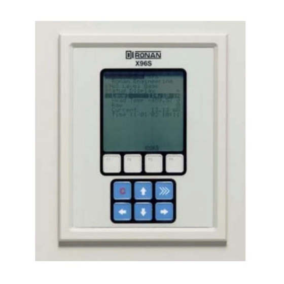
Page 40: X96S Local Display
X96S Ronan Engineering X96S Mass Flow Gage Menu Title The X96S Local Display consists of a 16 line by 21- Menu line 1 character display and a 10 key keypad. The top line of Menu line 2 the display is reserved for the analog bar, if enabled. -
Page 41: Editing Values
Editing Values The editing of different types of values is designed around the use of the four direction keys and up to 4 function keys. The left and right arrow keys are used to position the cursor to the letter/digit to be edited, and up and down arrow keys are used to scroll between the possible values for this position. -
Page 42: Installation
Installation Ronan's Mold Level Gauge uses a sealed radioactive cesium (Cs-137 ) or cobalt (CO-60) source which is Caution safe if handled properly. If your gauge is equipped with the SA or GS series source holder, you are required to obtain a specific license. Your Specific License company's specific license will name a Radiation Safety Officer (RSO) or Radiation Protection Officer (RPO). - Page 43 INSPECTION The source holder is equipped with an ON/OFF Mechanism. During shipment and storage the mechanism MUST BE SECURED in the OFF position with a padlock. Radiation Label If the padlock is damaged, broken, or missing, contact the RSO immediately. General License Label (if applicable) Handle Padlocked OFF...
- Page 44 INSPECTION Radiation Label SA10 General License (If applicable) Rod Padlocked OFF General License Radiation Label Label (for Specific License Users only) RLL1 or 2 Lock Tag (does not apply to RLL devices) WARNING THIS DEVICE MAY BE MOUNTED IN PLACE INITIALLY BY ANY PERSON PROVIDED THE SHUTTER REMAINS LOCKED IN THE OFF POSITION.
-
Page 45: Safety Precautions
Safety Precautions During installation the RSO will provide guidelines to assure safety. Consider the information presented in the Regulation/Safety Chapter of this manual, as well as the following general guidelines: The source holder must remain padlocked in the OFF position until installation is complete. Take all necessary precautions to assure that the source holder is not dropped or damaged. -
Page 46: Mechanical Mounting
Mechanical Mounting Review the Configuration Drawing which is included in the Drawing Chapter of this manual. Please reference the dimensional drawings located in the Drawing Chapter of this manual when installing the equipment. Consider the following general guidelines when Drawings mounting the sensor and detector: Avoid internal vessel obstructions such as baffles, agitators,... -
Page 47: Electrical Installation Of Interconnect Wiring
Electrical Installation of Interconnect Wiring DO NOT APPLY POWER until wiring is carefully checked. Drawings Wire the equipment according to the detailed interconnect drawing which is included in the Drawing section supplied . Follow local and national electrical codes for all interconnections. Drawings: Interconnect Consider the following guidelines before making any electrical... -
Page 48: Microprocessor Verification
Some Hardware Options: Some Hardware Options: 1 Input Board 2 Input Boards The Ronan X96S Microprocessor can be programmed for a variety of applications and Identification / Documentation configurations. The specific application supplied with each system is determined by the... -
Page 49: Power-Up
Before applying power, verify wiring per interconnect drawing supplied by Ronan. Ensure all boards are fully Ronan Engineering seated in frame’s slots. Close front door of the X96S Please wait . . . and secure the door... When power is applied the X96S runs a self-diagnostic program. -
Page 50: Password
Password Notice: To access the Programming Menu, the Password is 101010. Step 1: Power Up – You should now be on the Status Screen. Step 2: Press F3 to go back. Step 3: Now enter the password. (All digits are set at 000000 at this point.) Press to get the digit to be # one Press... -
Page 51: Calibration
Initial calibration consists of two parts, the flow-rate calibration and the density calibration. Calibration correlates the X96S's output to your actual process density. It instructs the microprocessor to read and store the detector counts for a low and high density of process. Once the system is conditioned to recognize the low and high density, it will provide a 4-20 mA output over the entire range of interest. -
Page 52: Reference Modes
Calibration Constant The two values, the reference density (d ) and the calibration constant (1/ut), are used by the X96S algorithm to calculate process density (d). IF USING SA1: IF USING RLL:... -
Page 53: Calibration Curve
Precise laboratory analysis will produce the most accurate and useful results. If the results are temperature compensated, you will need to enter the uncompensated values(s) into the X96S software. Final gauge measurements can be only as accurate as your sampling and analysis technique and level... -
Page 54: Density Low/Reference And High/Calibration
Important facts to remember – • Equipment should be running at normal environmental conditions – temperature, pressure, process flow, etc. • Final gauge measurements can only be as accurate as your sampling and analysis technique. • Remember to document all changes made to the factory parameters that are active in your system Density Low/Reference and High/Calibration The density calibration correlates the detector counts to the density in the pipe/or vessel. - Page 55 Quick Start Reference – Calibrating Density Ronan Engineering X96S Mass Flow Gauge Step 1 Start at the Status Display Status Display Mass Flow 3.05 t/hr Density 2.5 SPG From the Status Display Screen, Press the F3 (Lock) Key to display Proc Temp 50.00 deg...
- Page 56 ‘Low Reference Density’ Calibration (Have the process ready filled with water) Ronan Engineering X96S Mass Flow Gauge Scroll down ↓ to “Calibration” Press → to enter menu Main Menu Scroll down ↓ to “Cal Density” Press the → to enter menu...
- Page 57 High Density Calibrate Using the Ronan local display or HART communicator find the Main Menu; Scroll down until you reach and highlight Calibration. Access Calibration by pressing the right arrow key. Scroll down until you reach and highlight Cal Density. Access the Cal Density by pressing the right arrow key.
- Page 58 Step 1 High Calibrate (Have the pipe filled with process) Ronan Engineering X96S Mass Flow Gauge Scroll down ↓ to “Calibration” Press → to enter menu Main Menu Scroll down ↓ to “Cal Density” Press the → to enter menu...
- Page 59 The Density Calibration is complete. For future reference, document these items: (a) Environmental/process conditions (densities, temperatures, etc.) that influence the reference/ calibration. The next time a calibration is performed, you will need to duplicate the conditions, or account for the differences.
-
Page 60: Low And High Flow Calibration
PROCEDURE: For flow meters providing a voltage or current signal to the X96S. The flow must be stopped or running at the lowest speed during the Low Reference. Using the Ronan local display or HART communicator find the Main Menu;... - Page 61 Low Reference Flow Calibration (Have a “0” flow input ready) Ronan Engineering X96S Mass Flow Gauge Scroll down ↓ to “Calibration” Press → to enter menu Main Menu Scroll down ↓ to “Cal Flow Rate” Press the → to enter menu...
-
Page 62: High Flow Calibration
High Flow Calibration PROCEDURE (For flow meters providing a voltage or current signal to the X96S. The flow must be running at the highest speed during the High Calibration. Using the Ronan local display or HART communicator find the Main Menu;... - Page 63 Step 1 High Calibrate (Have the maximum flow input ready) Ronan Engineering X96S Mass Flow Gauge Scroll down ↓ to “Calibration” Press → to enter menu Main Menu Scroll down ↓ to “Cal Flow Rate” Press the → to enter menu...
-
Page 64: Configuration
After installation at your site, you may need to reconfigure the system to fit your application. The goal is to correlate the X96S output with your actual density readings. The list below summarizes the activities that are detailed in the remainder of this chapter: - Check the factory-default settings to be sure they are appropriate for your circumstances. -
Page 65: Detector
Detector Scintillator Detector Description The Ronan scintillation detector consists of three main components: The plastic scintillation crystal, the photo-multiplier tube (PMT), and the associated electronics. Scintillation Crystal The crystal used for the Mass Flow System is poly-vinyl toluene (PVT) plastic. The crystal produces light pulses which are proportional to the incident radiation events striking it. -
Page 66: Ion Chamber
10 ρA, so an electrometer amplifier is (DET-7471-XXX) required to convert the current to a low-impedance, high level voltage signal. The signal is then measured by the X96S Microprocessor, which converts the voltage signal to a output of 4-20mA for a specified measuring range. - Page 67 Detector Removal/ Replacement 1) Check NOTES below for illustrations and cautions that apply to your specific Detector Housing equipment. 2) Unscrew cap on detector housing. Detector Housing Cable Connector 3) Unscrew connector on top of detector. 4) Remove detector from housing. Detector 5) Carefully install replacement detector in housing.
- Page 68 Removing the Detector Amplifier Circuit Board Follow this procedure to remove the electrometer amplifier circuit board: 1. Remove the amplifier cover by unscrewing the hex socket head cap screws. 2. Remove the MS connector from the amplifier cover. 3. Remove the two 6-32 binding head screws, which secure the amplifier board to the...
-
Page 69: Electronics
Electronics X96-2001PL X96-2001PL is a CPU Module that comes without software. X96-2002PL X96-2002PL is the local Graphics L.C.D. Module. This optional module provides: • Graphic LCD • Keypad X96-2003PL X96-2003PL is the Ionization Chamber Interface Module. This optional module provides: •... -
Page 70: X96-2008Pl
X96-2008PL X96-2008PL is the Digital Input/Output Module. The module provides a total of 16 bits of digital I/O and wetting/encoder power. 8 isolated digital inputs are provided. These inputs can be configured for use as: • dry or live contact monitoring, •... -
Page 71: X96-2009Pl2
X96-2009PL2 X96-2009PL is the Scintillation Detector Interface Module. This optional module provides: • 1 isolated scintillation input (pulse counter, max signal 0-12 V, threshold 0.6 V) • 1 head temperature input (1 uA per deg K) • a 4-20 mA input (Ch. 2) •... -
Page 72: Options
X96S Mechanical Chassis Part Numbers PART NUMBER DESCRIPTION X96S-N4-( )-( )-6 X96S NEMA 4, Hubs, W/PGMR, 115VAC, 6-Slot, Encl, Mother Board, LCD X96S-N4-( )-( )-9 X96S NEMA 4, Hubs, W/PGMR, 115VAC, 9-Slot, Encl, Mother Board, LCD X96S-SM-1 X96S Surface Mount, 6 Position, with Motherboard... - Page 73 MODEL X96S Process Computer: Microprocessor-based unit with a liquid crystal display, push-button interface, HART Communications, process control outputs, process condition inputs, serial communications. Chassis: 19” rack mount, surface mount, or panel mount. Enclosure: Standard NEMA-4 Stainless Steel NEMA-4X Explosion Proof Electrical: Power inputs: 90-240VAC +/-15%, 50-60 Hz;...
- Page 74 SAMPLE DRAWINGS SERIES X96S-N4 X96S Sample drawing only. See the drawing section of your packet for specifics.
- Page 75 Sample drawing only. See the drawing section of your packet for specifics.
- Page 76 Mounting Plate Sample drawing only. See the drawing section of your packet for specifics.
- Page 77 21200 Oxnard Street Measurements Division Woodland Hills, California 91367 U.S.A. 8050 Production Drive (800) 327-6626 • FAX (818) 992-6435 Florence, Kentucky 41042 U.S.A. E-Mail: sales@ronan.com (859) 342-8500 • (859) 342-6426 Web Site: http//www.ronan.com E-mail: ronan@ronanmeasure.com X96S Mass Flow 120607 Printed in U.S.A.
Need help?
Do you have a question about the X96S and is the answer not in the manual?
Questions and answers