
Related Manuals for KINGSINE K68i

Summary of Contents for KINGSINE K68i
-
Page 1: Instruction Manual
K68i / K68 Relay Tester Instruction Manual Version: 1.3 Kingsine Electric Automation Co., Ltd. - Page 2 Note: This manual is applicable for KINGSINE K68i and K68 Relay Tester but it is compiled to use K68i as example. The corresponding updated software and functions instruction will be released on our website (www.kingsine.com.cn), when updating the software and increasing the contents. In order to obtain the latest and first-hand information, please pay more attention to the latest news on our website.
-
Page 3: Table Of Contents
Catalogue Chapter 1 Overview ..........................3 1.1 System Description ........................3 1.2 Technical Parameters ......................4 1.3 Amplifier for Voltage and Current ..................7 1.4 Package list ..........................7 1.5 After service: ..........................7 1.6 Attention:..........................8 Chapter 2 Panel Description ........................9 Chapter 3 Testing Operation ......................12 3.1 Main Menu...........................12 3.2 Basic Operations ........................13 3.3 DC Relays Testing........................15... -
Page 4: Chapter 1 Overview
1.1 System Description K68 Series Relay Tester is new All-in-One protections testing systems developed independently by KINGSINE on the basis of Windows CE system, which adopts the embedded system, the latest high-speed DSP processor and ultra-large-scale field programmable logic devices FPGA. -
Page 5: Technical Parameters
K68 Series Protection Relay Test Set K6 Series Protection Relay Tester main Tech description Model K68i Factor AC Current I 3*35A 3*35A AC Voltage U 4*130V 4*300V DC Current I 3*20A 3*20A DC Voltage U 1*150V 1*150V DC Voltage Ubc... - Page 6 K68 Series Protection Relay Test Set Rise/down time <50µs Resolution Generators, general ≤10μS Voltage and Current Synchronism Range 0 ... 1000 Hz Accuracy / drift Error < 0.001Hz at 0 ... 50Hz Frequency Harmonic superimpose 2-9 orders Resolution 0.001Hz Range 0°...
- Page 7 K68 Series Protection Relay Test Set Nominal frequency 50/60±10% Hz Environmental conditions Working temperature -5°C... 55 °C -20°C... 75 °C Storage temperature Humidity range 5 ... 90 %, non-condensing Alloy aluminum Weight 24KG Dimensions 360(D)×140 (W) ×460 (H) mm Interface RJ 45, USB,RS232, PS/2,VGA...
-
Page 8: Amplifier For Voltage And Current
K68 Series Protection Relay Test Set 1.3 Amplifier for Voltage and Current Current generator and voltage generator have no current booster and no voltage booster, but direct coupling mode is adopted by them, which enables the power supply’s frequency output range to be from 0Hz to 1000Hz, outputting DC and all AC voltage or AC current in all frequency. -
Page 9: Attention
K68 Series Protection Relay Test Set Attention: There are good Grounding picture in the right bottom of each interface menu. The grounding link is abnormal if showing picture In order to insure the test security and the accuracy of testing result, please check the power supply whether the grounding is proper. -
Page 10: Chapter 2 Panel Description
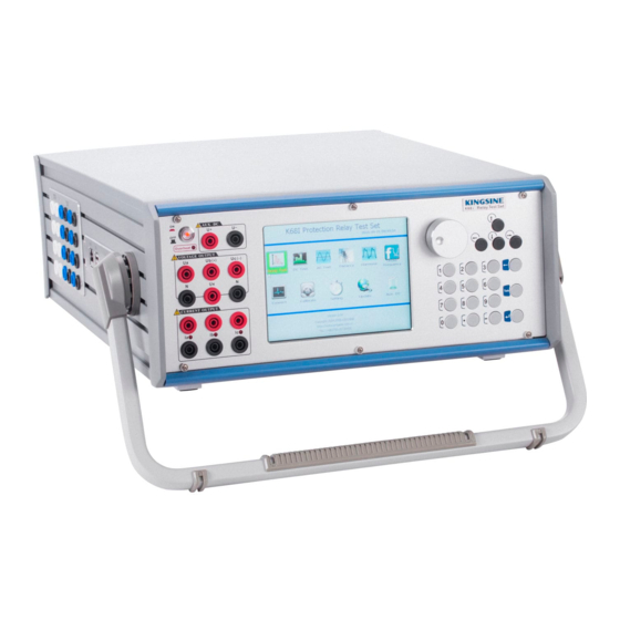
K68 Series Protection Relay Test Set Chapter 2 Panel Description Fig. 2-1 Panel Description (1) 6.4” TFT LCD screen (2) U(+) and U(-) are for Aux. DC supply, Power amplifier button: Press the button to start amplifier, while amplifier stop (3)... - Page 11 K68 Series Protection Relay Test Set terminal of charged contact is supposed to connect to public terminal TN (HN).
- Page 12 K68 Series Relay Tester Fig. 2-2 Panel Description Binary Output Binary Input Binary Input USB interface,is meant to be external connective to various VGA interface, is meant to be external connective to various VGA display PS/2 mouse or keyboard, is meant to be external connective to PS/2 mouse or keyboard at one time RJ45 interface, is meant to have data transmission between network and computer;...
-
Page 13: Main Menu
K68 Series Relay Tester Chapter 3 Testing Operation Main Menu The main interface of user Operation is shown as below after set software start running: Fig 3.1-1 Main menu Users may choose to enter the function modules required with the Rotary encoder or mouse and can also switch to choose the function modules with the first shortcut key or the direction key on the left of the external keyboard and then press ‘Enter’... -
Page 14: Basic Operations
K68 Series Relay Tester company name, website and telephone of the current system. The reference of the first edition of K68i Instruction such as software upgrade or content supplement. The real function should refer to the set latest version as software upgrading. - Page 15 K68 Series Relay Tester Switch the light load and heavy load of the Relay Tester. Under the normal circumstances, the Relay Tester outputs light load; when the impedance value is greater with load or the greater current is output in the Relay Tester; it is proposed to switch the state of the heavy load before testing.
-
Page 16: Dc Relays Testing
K68 Series Protection Relay Test Set 3.3 DC Relays Testing Click‘DC Test’ module of the Main menu and enter Direct Current interface, This Module test manually and automatically action value and return time of AC current/Voltage relay as shown in Fig. - Page 17 K68 Series Protection Relay Test Set Fig. 3.3-2 DC Relays Testing 3.3.2 Parameter setup of the set: Variable : including Amplitude Value, phase and frequency, one of which can be chosen as a variable and eight channels(five-way voltage and three-way current)of which can also be chosen as variable output.
- Page 18 K68 Series Protection Relay Test Set meanwhile, action time and action value are recorded. After testing, the setup parameters will be changed to re-test without clicking ‘Stop’ button to stop the test, for the parameter can be changed directly. : Only adapt to Automatic test, including ‘Action stops’ and ‘Action returns’ mode. Mode Pick-up: Variables change to strop from the starting value to the final value in accordance with step size or receive the protection signal to stop the testing process in the process of the...
- Page 19 K68 Series Protection Relay Test Set Fig. 3.3-3 Direct Relays Testing 1) Testing connection Connect the testing terminals of the relay or the protection device to be tested with the corresponding output port of the current or voltage by wire and connect the contact of the relay or the output contact of the protection device with Binary Input port of the Relay Tester by wire.
- Page 20 K68 Series Protection Relay Test Set ‘Save’ to save results and ‘View’ to preview the selected testing report.
-
Page 21: Ac Relays Testing
K68 Series Protection Relay Test Set 3.4 AC Relays Testing Click ‘AC Test’ module on the Main menu with the mouse and enter Alternating Current interface, as shown in Fig. 3.4-1: Fig. 3.4-1 AC Test The AC test as AC Current and Voltage Source can output 4-channel Voltage and 3-phase Current for various manual and automatically test. - Page 22 K68 Series Protection Relay Test Set 3.4.1 Interface Introduction to the set: There are 3 areas in the interface: ① On the left upper area of the interface: Set every variable for the starting value, the final value and current and step size for AC voltage and current to be tested, where: Marking ‘√’...
- Page 23 K68 Series Protection Relay Test Set and Action value automatically are recorded. After testing, it needs to change the parameters set and test again without stopping the button to stop the test, directly changing the parameters. : Only for Automatic test, including ‘Action stops’ and ‘Action returns’ modes. Mode Pick-up: Variable change to stop from the starting value to the final value or receive the protecting action signal in the process of change to stop the test.
- Page 24 K68 Series Protection Relay Test Set Fig. 3.4-2 AC Relays Testing 1) Testing Connection Connect the terminal of the relay or the protection device to be tested with the output port of the corresponding current or voltage by wire and connect the Action contact of the relay or the output contact of the protection device with Binary Input port of the Relay Tester by wire.
- Page 25 K68 Series Protection Relay Test Set the relay, Save Report dialog box is automatically sprung out from the system. 3.4.4 Testing Example Testing Task: Check over current at Zero-sequenceⅡstep of ISA-311 circuit protection. Testing Item: Check Action Current, Action Time and Return Coefficient Protecting fixed value: Zero-sequence reverse time limit input/exit: Exit...
- Page 26 K68 Series Protection Relay Test Set 2) Parameter Setup: Variable type: A phase current amplitude value Frequency: 50Hz Starting current value: 5.00A Change step size: 0.50A Testing mode: manual mode 3) Test: Click ‘Run’ key to begin the test and record automatically Action value, Return Value and Return Coefficient.
-
Page 27: Distance/ Zero-Sequence Relays Testing
K68 Series Relay Tester Distance/ Zero-sequence Relays Testing Click ‘Distance’ module on the Main menu and enter the interface. The Testing Module is mainly applied for Distance Test of circuit protection, such as the distance and zero-sequence; Be able to simulate various single-phase grounding, two-phase grounding, inter-phase and three-phase short-circuit fault in the power system, including instantaneous/transient, permanent and transitional/switch faults. - Page 28 K68 Series Relay Tester Fig. 3.5-2 Distance/ Zero-sequence Relays Testing 3.5.1 Interface Introduction to the Set There are 3 areas in the interface and Press ‘PgDn’ to the next page interfaces ① it is the area to control parameter setup. ②...
- Page 29 K68 Series Relay Tester Checkout of the fixed value of variable impedance of power frequency: Computation formula of short-circuit voltage Positive direction single-phase grounding short-circuit: V=(1+KL)kIZset+(1-1.05M)Un 3 Un Positive direction short-circuits between phases: V=2kIZset+ (1-1.05M) Reverse export short-circuit: Note: KL is zero-sequence compensation coefficient in the circuit, k is the multiple of short-circuit impedance, I is short-circuiting current, Zset is short-circuiting impedance setting, M is power frequency variable coefficient and Un is rated voltage.
- Page 30 K68 Series Relay Tester phase current is zero, and voltage comes back to the normal phase voltage ( V=Vnom) ; When PT is installed in the circuit, after disconnecting the fault phase, the phase current and voltage are zero. Z : there are two expression methods for the impedance value of the circuit or the load when there is fault: (Z∠θ°) or (R+jX).
- Page 31 K68 Series Relay Tester sequence, Kso is a real number and its void. Its imaginary part is zero. Zero-sequence Compensation Coefficient in the circuit: Klo= (Zlo-Zl1)/ (3*Zlo); Where: Zlo indicates Zero-sequence Impedance in the circuit. Zl1 indicates the impedance of the positive sequence. Generally, considering Ph (Zlo) =Ph (Zl1), Klo is also a real number.
- Page 32 K68 Series Relay Tester For the computation model of the constant power(system)impedance, when the amount of short-circuit impedance and the power impedance is near or equals zero, the computed short-circuit current will be over big, that is If>Imax. When the reminder of current beyond the limit is on the bottom of the screen.
- Page 33 K68 Series Relay Tester 3.5.3 Testing Process Click ‘Run’ button and enter the testing state after the parameters in the interface are set. User can change Binary Input and Binary Output under the testing state and then change fault state and the tested return result. The testing Operation process is different according to different testing items of circuit protecting the whole set, there are 3 conditions in detail: ◆...
- Page 34 K68 Series Relay Tester action time from beginning to simulate fault to the circuit action of the breaker trip. When testing of protecting the failure of the breaker matching linkage, the breaker’s performance should be simulated to test under the Operation of the positive and negative auxiliary bus and under the failure of starting the breaker in the protection circuit, respectively.
- Page 35 K68 Series Relay Tester 1)Testing Connection A.Connect the output terminal of voltage and current of the test device with the corresponding input terminal of current or voltage by test wire. B. Connect the trip export contact of the protection device with Binary Input contact A of the Relay Tester and connect the Action contact of re-switch with Binary Input contact H of the Relay Tester.
- Page 36 K68 Series Relay Tester 90 ° Check re-switches synchronism fixed angle value: Testing Connection: A.Connect the output terminal of voltage and current of the test device with the corresponding input terminal of the current or voltage by test wire. B. Connect the trip export contact of the protection device with Binary Input contact A of the Relay Tester and connect the Action contact of re-switch with Binary Input contact H of the Relay Tester, Parameter Setup:...
- Page 37 K68 Series Relay Tester Binary Input definition: A contact definition: Trip A; B contact definition: Trip B C contact definition: Trip C; H contact definition: Reclosing Ux Output setup: if not checking synchronism, it is not relative. Test: 1) Open Relay Tester and the Set Main menu, click ‘Distance’ module and enter the testing interface of the whole set.
-
Page 38: Harmonic Output Testing
K68 Series Relay Tester 3.6 Harmonic Output Testing Click the icon of ‘Harmonic’ on the Main menu and enter the Operation Interface of Harmonic. The Testing Module can control Test instrument and output AC and DC and harmonic to test automatically and manually, and oscillogram is used for real-time monitor of every output channel. - Page 39 K68 Series Relay Tester 3.6.2 Parameter Setup Harmonic setup: amplitude value and phase of fundamental and 12th harmonic of every channel can be set in the left upper area on the interface. For instance, click ‘UA’ and ‘IB’ button and switch the output channel to set the parameter or View. Testing mode: including Manual test and Automatic test.
- Page 40 K68 Series Relay Tester G. Process the report and choose whether to save the report. 3.6.4 Testing Example Protection Device: Shenzhen NARI ISA-387F Digital transmitter Differential Protection Device Testing Item: Fixed detection harmonic constraint characteristic (HV A-phase) Bill of Fixed value: Transformer Connection Mode Y/Y/D-11 CT ratio regulating coefficient is separately 1:0.5:1 at the first, second and third side.
- Page 41 K68 Series Relay Tester Function: Amplitude Testing mode: manual Option:IA Order: 2nd harmonic step:0.02A Save Parameters: Click ‘access parameter’, spring out the dialogue box of access parameter, and choose the file name of the testing report to be saved or input the new file name of the testing report again and click ‘Save’, to save parameters.
-
Page 42: Frequency Protections Testing
K68 Series Relay Tester 3.7 Frequency Protections Testing Click the icon of ‘Frequency’ on the main menu with the mouse and enter its interface. The Testing Module of Frequency protection including LF/LV/LI deloading and test the Action value, Action time, df/dt Action value, the closed value of voltage and the lockout value of current of various frequency relays and Low Frequency Decrease Load automatic device, as shown in Fig. - Page 43 K68 Series Relay Tester Fig 3.7-2 Frequency protection 3-Phase Output:Set the 3-phase output V / I Low-frequency: From :Set the starting change point of frequency. To :Set the final change point of frequency Auto slip:Set the change rat of frequency. :Set the change step size of frequency.
- Page 44 K68 Series Relay Tester Deglitch:JitterBuffer Time. Generally, it is 5ms to 15 ms and used to distinguish contact jitter from contact Action as the resistant export contact jitter time. When the closed or open time of the Action contact of the protection is less than the time (contact jitter), the contact Action will not be accepted.
- Page 45 K68 Series Relay Tester C. Input the starting value of change and the final value (should be consistent to the triggering frequency) and df/dt(less than df/dt lockout value)in the column of the frequency change scope and the change rate. D. Description of Test Flow In ‘Testing setup’, set ‘Pre-time’...
- Page 46 K68 Series Relay Tester Low Frequency Decrease Load Δ f/ Δ t lockout fixed value: 2.00Hz No Δ f/ Δ t lockout Low Frequency Decrease Load input: Exit Low Frequency Decrease Load no-current lockout input: Input Low Frequency Decrease Load no-current lockout fixed value: 1.00A Control circuit break-line alarm input: Exit...
- Page 47 K68 Series Relay Tester Amplitude Value(V)phase( ° ) Amplitude Value(A) phase( ° ) UA: 57.74; IA: 2 UB: 57.74; IB: 2 UC: 57.74; IC: 2 Testing setup: Function: Action frequency; Pre-time(S):2.00 Interval(S):0.20; Deglitch(ms):15 Hold(S):3.00; Binary Input: OR Change frequency setup: From(Hz):50.00;...
- Page 48 K68 Series Relay Tester Fig. 3.7-4 Low-Frequency Deloading Testing Report...
- Page 49 K68 Series Relay Tester 3.8 Aux DC Relay Tester Model K68i can provide relay protection device with independent Aux. DC power supply. The Aux DC output can be set according to the demand on the Aux DC switch of main interface, and the range is 0V~300V.
-
Page 50: Chapter 4 System Calibration, Settings & Update
K68 Series Protection Relay Test Set Chapter 4 System Calibration, Settings & Update 4.1 System Calibration Click on Calibrate icon to enter the interface of System Calibration, and calibrating password is required Please ensure that each item of standard instruments accord to the demand precision and is better to the set when entering as Fig. - Page 51 K68 Series Protection Relay Test Set 5. Clear:Delete the present calibrating coefficient of the relay tester 6. Password:Modify calibrating password 7. Exit:Exit the module of Calibrate Calibration methods: 4.1.1 AC Zero-offset Calibration Application:Is applied to calibrate DC content of AC current and of AC voltage Note: When AC offset, Meter’s anode and cathode corresponds to these of relay tester.
- Page 52 K68 Series Protection Relay Test Set Fig. 4.1-3 Voltage offset calibration ③Input actual offset, i.e. DC content of 10V, and to click Ok button ④After calibration of 10V, System will output 60V, and to input actual offset, click OK ⑤Click Save button to save the calibrated coefficient. 2.
- Page 53 K68 Series Protection Relay Test Set 4.1.2 AC Amplitude Calibration Application:Is applied to calibrate AC range Calibration method: this method is the same as that of AC offset calibration 4.1.3 AC Phase No need for calibration because of hardware installed in relay tester. And the phase discrepancy is from 0.1 to 0.2 digress.
- Page 54 K68 Series Protection Relay Test Set for ‘Select’, it can make calibration for fixed point Select UA frequency 50Hz, and to calibrate the frequency when UA output 50Hz, 100V ⑴ Frequency range of Voltage’s calibration The voltage for calibrating corresponds to one of frequency, and the voltage has two shifts for output: 10V and 60V.
- Page 55 K68 Series Protection Relay Test Set Fig. 4.1-6 Voltage frequency range calibration (2) .Three phase current calibration The current for calibrating corresponds to one of frequency, and the current has two shifts for output: 5A and 8A. The following are taken IA as example to calibrate its range value less than 100Hz.
-
Page 56: Ip Setting
K68 Series Relay Tester 4.2 IP Setting Click ‘IP Setting’ module on the Main menu and enter the following interface, as shown in Fig. 4. 2-1: Fig.4. 2-1 IP Setting The module is used to set IP address and system time. IP is for internet/LAN PC-linking upgrading and report uploading, which need IP of set is in the same network section as the PC for data PC-linking and please restart the set after IP setting. - Page 57 K68 Series Relay Tester Fig.4. 2-2 IP Setting Fig.4. 2-3 Date Setting...
-
Page 58: Software Upgrade And Report Upload
K68 Series Relay Tester 4.3 Software Upgrade and Report Upload Before System Upgrade(at the local)and report upload, at first set IP address of the Test set and ensure it under the same subnet, 1. IP ADDRESS SETUP for the linking computer Operate the program of the upper computer and click ‘IP Setting’... - Page 59 Fig. 4.3-3 System Upgrade (1)Local Upgrade Download the latest upgrade packet of set to the local computer manually from KINGSINE website and transmit the upgrade file to the Test set by the computer, the test set has been online correctly before upgrading as shown in Fig. 4.3-4:...
- Page 60 K68 Series Relay Tester Fig. 4.3-4 Local Upgrade Special Note: Local Upgrade must be followed under the steps below: (1)Click the Test set ‘System Upgrade’ and enter ‘Local Upgrade’ menu, the present software version number is displayed on the interface of the system and click ‘Next’ to prepare online upgrade.
- Page 61 Click ‘Enter’ and enter the following interface. (2)U Disk Upgrade Download the latest upgrade packet of set to U disk manually from KINGSINE website and transmit the upgrade file to the Test set by USB interface of the Test set(Note: the upgrade packet can not be saved after being opened, or else the system can not search the upgrade packet.)...
- Page 62 K68 Series Relay Tester Online upload must be followed under the steps below. (1) Click ‘Upgrade’ and enter ‘Local’ menu, as shown in Fig.4.3-7: Fig. 4.3-7 Online Upload Report (2) Choose the report to be uploaded in ‘System Report’ column and click ‘Next’ and list the reports in ‘...
- Page 63 K68 Series Relay Tester Fig. 4.3-8 Local Upload Operate the program of the upper computer and click’ Upload Report’, the following interface appears. Choose the file path to be saved and click ‘Enter’ and upload the repot. (2) Upload report by U disk Upload the report to U disk with USB interface of the Test set and copy the report to a computer by U disk to print it.
- Page 64 Address: 6/F, Block 4-CD, TianAn Cyber Park, Shenzhen 518048, China Tel: +86-755-83418941 Fax: +86-755-88352611 Email: roger@kingsine.com.cn Website: www.kingsine.com.cn...
Need help?
Do you have a question about the K68i and is the answer not in the manual?
Questions and answers