Table of Contents
Advertisement
Quick Links
Quick Start Guide, AlphaGateway SMG-HP, Model AG100D-PoE+
The AlphaGateway SMG-HP AG100D-PoE+ provides 2 x 10/100/1000 BASE-T Ethernet ports with support for IEEE802.3af/at PoE/PoE+, with a
power output of 30W per port. The included DOCSIS 3.1 cable modem provides power system status monitoring and up to 1 Gigabit connectivity.
The unit connects to the HFC Coaxial Access network through a power-passing tap at any location within the HFC voltage range (44–90Vac Quasi
Wave), and transforms the HFC power to a voltage suitable for connected devices.
AlphaGateway SMG-HP Connections
1
3
3
4
5
018-357-B1-001, Rev. A (08/2019)
2
TOP
FRONT/LID
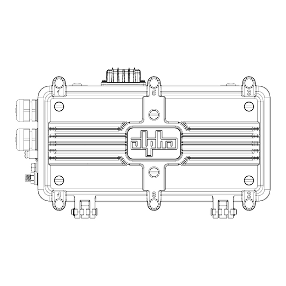
Fig. 1, Connections and Ports
14.8" (375 mm)
BACK/BASE
Fig. 2, Dimensioned Views
Access port cover for System LEDs / Reset Button
1
GPS Antenna
2
IP67 Cable Gland for network cables
3
Ground Lug
4
AC Input via F-connector
5
(44-90Vac Quasi Square HFC Coax
5/8-24 SCTE-91 compliant)
Product label location
6
Pin to F-connector trim length guide
7
6
7
RIGHT
3.9" (98 mm)
8.4" (213 mm)
LEFT
1
Advertisement
Table of Contents

Related Manuals for EnerSys AlphaGateway SMG-HP AG100D-PoE+


Summary of Contents for EnerSys AlphaGateway SMG-HP AG100D-PoE+
- Page 1 Quick Start Guide, AlphaGateway SMG-HP, Model AG100D-PoE+ The AlphaGateway SMG-HP AG100D-PoE+ provides 2 x 10/100/1000 BASE-T Ethernet ports with support for IEEE802.3af/at PoE/PoE+, with a power output of 30W per port. The included DOCSIS 3.1 cable modem provides power system status monitoring and up to 1 Gigabit connectivity. The unit connects to the HFC Coaxial Access network through a power-passing tap at any location within the HFC voltage range (44–90Vac Quasi Wave), and transforms the HFC power to a voltage suitable for connected devices.
-
Page 2: Pre-Installation
NOTICE: Each connected Ethernet device will register as a distinct CPE device; these may need fixed IP addresses depending upon the usage model. Ensure that unused ports are covered with plugs. Remove only the plugs necessary for installation. For other mounting options, refer to the SMG-HP Technical Manual (Alpha p/n 018-357-B0). Pre-Installation Tools Required (User-Supplied): Torque Wrench with:... - Page 3 Strand Mount Installation Procedure 1. Remove the two nylon screws from the top (or back, e.g., if hanging the SMG-HP horizontally) of the enclosure. 2. Take the two strand mount brackets from the strand bracket installation kit (3" bracket kit, Alpha p/n 746-627-25, 2.5"...
-
Page 4: Horizontal Configuration
Horizontal Configuration This method is recommended for installations in areas with space limitations within the communications space between poles, or when a connected application device (e.g., WiFi AP, camera) is mounted directly to the SMG-HP’s lid. 1. Remove the two nylon screws from the back of the enclosure. 2. -
Page 5: Connection And Start-Up
Connection and Start-Up WARNING! ELECTRICAL HAZARD Low impedance grounding is mandatory for personnel safety and critical for the proper operation of the cable system. WARNING! ELECTRICAL HAZARD Prior to connection, the technician must verify the coax cable being connected to the SMG-HP is not energized. HFC Hardline Coax (44-90Vac Quasi Square Wave + DOCSIS RF) Power-passing Tap/Directional Coupler Input RF/AC to SMG-HP via cable with F-connector... -
Page 6: Connection Procedure
Connection Procedure NOTICE: To ensure no power issues are encountered, such as shorting the center conductor, connect the drop cable to the SMG-HP first, then connect the drop cable to the power passing tap. PoE+ Port 1 1. Connect the coax to the Pin to F-connector, and with an open-ended torque wrench, torque to 35 in-lbs (4.0 Nm). - Page 7 Ethernet Cable Connector Assembly NOTICE: Verify all pieces of the assembly are present and used in the correct sequence to prevent the ingress of water into the SMG-HP. 1. Remove (and save) the sealing plug from the sealing nut. Remove the sealing nut, insert and cage from the port. 2.
- Page 8 Verification of Ethernet Status The PoE controller will disable power to the Ethernet connection ports until a valid PoE powered device is connected to the port. When such a connection is made, the Link/Activity LED (green) will either be on solid (indicating Link), or blinking to indicate activity and the PoE+ Status LED (orange) will be illuminated.
-
Page 9: Surface Mount Installation
Alternate Installation Methods Surface Mount Installation 9.69" (246.2 mm) 1/4-20x1/2" hardware Wall-mount hardware Wall-mount hardware 1/4-20x1/2" hardware Fig. 13, Gateway Wall Mount Bracket Tool for Installation: • Torque Wrench with: 7/16" (11 mm) Socket 1/2" (13 mm) Socket Open-ended 7/16" (11 mm) wrench Slot head screwdriver (to remove nylon screws during bracket installation) Hand Drill 1. - Page 10 Alternate Installation Methods, continued Surface Mount Installation, continued NOTICE: Note the orientation of the bracket. The SMG-HP must be installed on the bracket as shown. 1/4-20x1/2" mounting hardware (4 places) Fig. 14, Attaching the SMG-HP to the bracket 4. Use a standard screwdriver to remove the four nylon protection screws from the back of the enclosure.
-
Page 11: Pole Mount Installation
Alternate Installation Methods, continued Pole Mount Installation Tools for Installation: Torque Wrench with: 1/4-20x1/2" 7/16" (11 mm) Socket mounting hardware (4 places) 1/2" (13 mm) Socket Open-ended 7/16" (11 mm) wrench Slot head screwdriver (to remove nylon screws during Slots for mounting bracket installation) straps (3 per side) Hand Drill... - Page 12 Alternate Installation Methods, continued Pole Mount Installation, continued 4. Attach SMG-HP and bracket to the pole with stainless steel (or better) banding. 5. Properly ground the SMG-HP by connecting a #6 AWG wire from the ground lug mount to the strand ground per local code.
- Page 13 Alpha Technologies Services, Inc. © 2019 Alpha Technologies Services, Inc. All Rights Reserved. Alpha reserves the right to change specifications without notice. an EnerSys company 018-357-B1-001, Rev. A (08/2019) Alpha is a registered trademark of Alpha Technologies Services, Inc. For more information visit www.alpha.com...
Need help?
Do you have a question about the AlphaGateway SMG-HP AG100D-PoE+ and is the answer not in the manual?
Questions and answers