
Related Manuals for EnerSys Alpha


Summary of Contents for EnerSys Alpha
- Page 1 Alpha Broadband Small Cell (BSC) ® Outdoor Gateway Technical Manual Effective: January 2024...
- Page 2 Safety Notes Review the drawings and illustrations contained in this manual before proceeding. If there are any questions regarding the safe installation or operation of the system, contact Alpha Technologies Services, Inc., an EnerSys company, or the nearest Alpha product sales representative. Save this document for future reference.
- Page 3 ® Alpha shall not be held liable for any damage or injury involving its enclosures, power supplies, generators, batteries or other hardware if used or operated in any manner or subject to any condition not consistent with its intended purpose or is installed or operated in an unapproved manner or improperly maintained.
-
Page 4: Table Of Contents
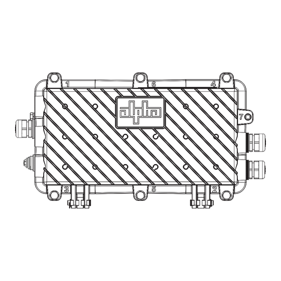
Contents Alpha Broadband Small Cell (BSC) Outdoor Gateway Safety Notes ..........6 ® Alpha Grounding System Installation Procedure ................6 1.0 Introduction ........................... 7 1.1 Alpha BSC Outdoor Gateway Connections......................7 ® 2.0 Installation ............................. 8 2.1 Strand Mount Installation Procedure ........................9 2.2 Wall Mount Installation Procedure ........................ - Page 5 Figures Fig. 1-1, Connections and Ports ..............................7 Fig. 1-2, Dimensioned Views ..............................7 Fig. 2-1, Strand Mounting Bracket Installation, Vertical Configuration ..................9 Fig. 2-2, Ground Lug Detail ..............................9 Fig. 2-3, Strand Mounting Bracket Installation, Horizontal Configuration ................10 Fig. 2-4, Ground Lug Detail ..............................10 Fig.
-
Page 6: Alpha ® Broadband Small Cell (Bsc) Outdoor Gateway Safety Notes
System Grounding with Low Voltage Disconnect Switch in use: For installations utilizing Alpha Technologies’ optional low-voltage disconnect switch (Alpha p/n 021-111-20), use a #6 AWG wire to connect the ground lug on the baseplate of the switch to a driven ground rod in accordance with local electrical codes. -
Page 7: 1.0 Introduction
1.0 Introduction This guide addresses the identical installation and configuration of the following Alpha Broadband Small Cell (BSC) ® outdoor gateway models: • (Power only) AG300P-AC90, AG300P-AC120 • (Power + DOCSIS 3.1) AG300D-AC90, AG300D-AC120 ® Additional product specifications are included at the end of this document. -
Page 8: 2.0 Installation
Set up a billing account (if applicable). • As appropriate, provision each connected device using the device’s MAC address. • The Alpha BSC outdoor gateway can also be connected to the hard coax through a directional coupler. ® NOTICE: • Each connected device will register as a distinct CPE device; these may need fixed IP addresses depending upon the model. -
Page 9: Strand Mount Installation Procedure
79.7–88.5 in-lb (9–10 Nm). 2. Take the two strand mount brackets [2] from the strand bracket installation kit (3" bracket kit, Alpha p/n 746-627-23 or 2" bracket kit, Alpha p/n 746-627-24), remove the two plugs from the top of the enclosure, and secure the mounting brackets in place. -
Page 10: Fig. 2-3, Strand Mounting Bracket Installation, Horizontal Configuration
79.7–88.5 in-lb (9–10 Nm). 2. Take the two strand mount brackets [2] from the strand bracket installation kit (Alpha p/n 746-627-23) and remove the two plugs from the top of the enclosure, securing the mounting brackets to the Alpha BSC outdoor gateway in their ®... -
Page 11: Wall Mount Installation Procedure
Fig. 2-5, Gateway Wall Mount Bracket Align the bracket (Alpha p/n 746-645-20) into the desired installation position on the wall. Mark the four holes where the 5/16" (M8) hex head screws will be drilled into the wall. 2. Drill four pilot holes into the wall using the wall mount bracket as a template. If mounting to drywall, a stud should be located and used to secure any two of the hex head screws. -
Page 12: Pole Mount Installation Procedure
Flat Washer Fig. 2-6, Pole Mount Installation Configuration Secure the pole mount bracket (part of Pole Mount Bracket set, Alpha p/n 746-861-20) to the pole using the metal straps. 2. In the top two mounting bracket holes of the Alpha BSC outdoor gateway, partially tighten two of the 1/4"-20 bolts,... -
Page 13: Connection And Start-Up
Installation, continued Connection and Start-Up Fig. 2-7, Connection Diagram HFC hardline coax (45-90VAC quasi-square wave + DOCSIS ® Directional coupler / splitter Ethernet port Input power (also RF signal for data backhaul) Strand-mounted BSC outdoor gateway AC outputs (up to 4) WARNING! ELECTRICAL HAZARD Low impedance grounding is mandatory for personnel safety and critical for the proper operation of the cable system. - Page 14 Installation, continued Prior to applying power, ensure the unit is properly grounded as described in the Alpha Grounding System ® Installation Procedure on page 6. CAUTION! To protect the installer from working on a live unit, connect the coax cable to the BSC outdoor gateway first.
-
Page 15: Installing The Output Power Cable
Ground 10. Verify the output indicator LED is illuminated, signifying Line Neutral power is present (applies to all four models of the Alpha BSC outdoor gateway). ® Underside of connector showing screw terminals Completed cable gland assembly Sealing insert... -
Page 16: Installing The Ethernet Cable
This applies to the AG300D models. The Ethernet cable can be installed before or after start-up. Remove and disassemble the corresponding cable gland. See Fig. 2-9. 2. Route the Ethernet cable through the cable gland and into the Alpha BSC outdoor gateway. -
Page 17: Verification Of Ethernet Status
Installation, continued Verification of Ethernet Status Once the Alpha BSC outdoor gateway is powered up, the power outputs will activate and the cable modem (CM) boot ® process will begin. Pre-provisioning phase (unit is not yet provisioned by the CMTS): •... -
Page 18: Fig. 2-12, Torque Values For Cable Glands
70 in-lb (8 Nm). NOTICE: A seventh bolt is available as an optional Alpha security bolt (Alpha p/n 647-189-13). Torque the security bolt to 35 in-lb (4 Nm). For cable gland replacements, contact tech support at +1 800-863-3364. -
Page 19: Managing The Alpha Bsc Outdoor Gateway
3.0 Managing the Alpha BSC Outdoor Gateway ® Local Access – Web Interface The Alpha BSC outdoor gateway provides embedded Ethernet communications, allowing the user to view and configure ® settings via a web interface. The local management port (seen in the figure below) is used as a connection point between the BSC outdoor gateway and a computer’s Ethernet port. -
Page 20: Remote Access - Web Interface
• For web server (HTTP) access, port 80 must not be blocked and the computer must have access to the private cable modem network. • The BSC supports SNMPv1, v2C and v3. Contact Alpha Technical Support to obtain the supported MIBs. -
Page 21: Fig. 3-3, Upstream/Downstream Rf Signal Power Screen (Sample)
Managing the BSC, continued Upstream and Downstream RF Signal Power This screen provides data with regard to signal frequency and respective power level, (e.g.,603 Mhz, at -5.0 dBmv). Fig. 3-3, Upstream/Downstream RF Signal Power Screen (Sample) RF Attenuation Attenuation values for upstream/downstream signals can be applied and/or modified via this section. This adjusts the power level of the frequency’s signal. -
Page 22: Fig. 3-5, Ofdm Downstream Data (Sample)
Managing the BSC, continued OFDM Downstream / Upstream Data The DOCSIS 3.1 communications module in the Alpha BSC outdoor gateway utilizes orthogonal frequency-division ® ® multiplexing (OFDM) in order to encode data on multiple carrier frequencies. This method allows for increased transmission speed with the same frequency range. -
Page 23: 4.0 Technical Specifications
4.0 Technical Specifications Model Description and Part Numbers Model Description AG300P-AC90 AC90-300 W – Power Only 018-356-50 AG300D-AC90 AC90-300 W – With DOCSIS 018-356-20 ® AG300P-AC120 AC120-300 W – Power Only 018-356-60 AG300D-AC120 AC120-300 W – With DOCSIS 018-356-30 ® Mounting and Cables Description BKT-AGW-SS... -
Page 24: Environmental Specifications And Agency Certifications
44.3 – 53.1 in-lb (5 – 6 N-m) Carriage Bolt (2 bolts) Strand mount bracket clamp 79.7 – 88.5 in-lb (9 – 10 N-m) Security bolt (Alpha p/n 647-189-13) Enclosure lid 35 in-lb (4 N-m) Hardline Coax Input 5/8 × 24 HFC Input Port 44 in-lb (5.0 N-m) -
Page 25: Network Specifications
4.0 Technical Specifications, continued Network Specifications AG300D-AC90 AG300D-AC120 Network Delivery (LAN) Network Delivery Ethernet - IEEE ® 802.3-2015 # Network Delivery Ports Distance 100M LAN Services TCP/IP , IPv4, IPv6, DHCP , L2VPN Backhaul (WAN) Compliance DOCSIS 3.0, 3.1 ® Single chip Intel Puma™... -
Page 26: 5.0 Appendix
5.0 Appendix Configuring a Static IP Address (Windows 8, Windows ® ® Use the following procedure to configure a static IP address on a laptop or computer with the Windows 8 or ® Windows 10 operating system: ® Navigate to Control Panel. 2. - Page 27 Tel.: Toll Free North America: +1 800-322-5742 | Outside US: +1 360-647-2360 | Technical Support: +1 800-863-3364 For more information visit www.alpha.com © 2024 Alpha Technologies Services, Inc., an EnerSys company. All Rights Reserved. Trademarks and logos are the property of EnerSys and its affiliates except Slo-Blo...
Need help?
Do you have a question about the Alpha and is the answer not in the manual?
Questions and answers