Advertisement
Quick Links
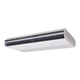
GME Series
Underceiling/Console
Split System Indoor Units
GENERAL
The GME Underceiling Indoor Unit are
designed to be coupled with the OSA
outdoor units and controlled by the HAN-L6
room temperature controller. Units must be
installed in accordance with all national and
local safety codes.
Combinations
One GME 152 with one OSA 45
One GME 222 with one OSA 73
One GME 302 with one OSA 100/101
One GME 402 with one OSA 126/127
One GME 502 with one OSA 147/148/150
One GME 702 with one OSA 180/181
One GME unit c/w HAN-L6 Controller and
one GME unit without controller (slave) can
be connected in tandem to one single
circuit Outdoor Unit. Tandem combinations
available are:
Two GME 152 with one OSA 73
Two GME 152 with one OSA 85
Two GME 222 with one OSA 126/127
Two GME 302 with one OSA 180/181
Two GME 402 with one OSA 220/221
One GME 222 and GME 152 (slave) with
one OSA100/101
UNPACKING UNITS
The OSA outdoor unit and GME indoor unit
are cartoned separately. Unpack each
item carefully. Examine for transit damage.
Fig. 2 Mounting Bracket Detachment
VIEWED FROM BELOW
ENDCAP
MOUNTING
BRACKET
SCREW SECURING
ENDCAP
c/w HAN-L6 Controller
GME UNIT
Components
The GME carton includes:
1. GME indoor unit.
2. HAN-L6 Wall Control (shipped inside
unit behind filter panel)
3. Insulated condensate drain extension kit.
4. Right-angled suction pipe extension
c/w lock nut and teflon seal.
Fig. 1 Mounting Options
MOUNTING ROD CENTRES
HINGED DOWN
FILTER PANEL
UNDERCEILING
MOUNTING
OPTIONAL
WALL
MOUNTING
(RECESSED)
Installation &
Maintenance
INSTALLATION
Positioning & Mounting
The GME is designed to be installed :
a. suspended horizontally beneath a level
or sloping ceiling, or
b. floor or wall mounted (i.e. vertically).
Note: For an extra low profile the unit can
be recessed into the ceiling (or wall).
Preparation
Prior to mounting the GME the mounting
brackets must be detached from each end
of the unit.
1. Open the end filter panel and locate the
screw securing the unit endcaps (refer
figure 2).
2. Remove the endcap securing screw and
retain.
3. Remove the endcap by first sliding it
forward approx. 20 mm, then pull
outwards away from end of the unit.
4. Release each mounting bracket from
behind the two bolts securing them to
the unit.
5. Remove the floor mounting base from
the back of the GME if when ceiling
mounted it is required to fit flush to the
wall.
Underceiling Mounting
Locate the GME near a wall to take full
advantage of the long supply air throw and
to hide the condensate drain pipe (and
other connections) exiting at the rear of the
unit.
Refrigeration and wiring connections are
via the top or the rear access holes. A right-
angled suction pipe extension is supplied to
facilitate top exit.
Fig. 3 Mounting Detail
MOUNTING ROD
MOUNTING
BRACKET
30 mm
MAXIMUM
GME 152: 942 mm
GME 222, 302: 1203 mm
GME 402 – 702: 1803 mm
Underceiling Installation
1. If an extra low profile installation is
preferred, first cut the required ceiling
aperture.
Advertisement

Related Manuals for TemperZone GME Series


Summary of Contents for TemperZone GME Series
- Page 1 GME Series c/w HAN-L6 Controller Underceiling/Console Installation & Split System Indoor Units Maintenance GENERAL GME UNIT INSTALLATION The GME Underceiling Indoor Unit are Components Positioning & Mounting designed to be coupled with the OSA The GME carton includes: The GME is designed to be installed : outdoor units and controlled by the HAN-L6 1.
- Page 2 4. GME electrical box–to–OSA outdoor 2. Install four M8 threaded hanging rods GME 402 refrigerant line connections are: unit interconnecting lead; (not supplied) to protrude no more than Liquid: 13 mm OD (1/2") flare nut 12.5 m or 25 m; 7 core. 30 mm below the level of the mounting Gas: 19 mm OD (3/4") sweat 5.
-
Page 3: Indoor Units
WARNING if required. Do not try to set up/down This pamphlet replaces the previous louvre manually. This unit is designed for use ONLY with the issue no.s 2562 dated 12/05. 7. With the motorised louvre switched off, refrigerant HCFC-22. The use of other Wiring revision C. - Page 4 05/06 Pamphlet No. 2578 © temperzone limited 2006...