Table of Contents
Advertisement
Quick Links
Download this manual
See also:
Manual
Installation Instructions
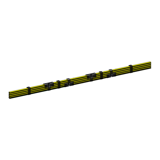
Expansion Module and Expansion Element
Program 0815
Order number:
0815xx-...
Contents
1
Terminology ............................................................................................................................................................ 3
2
Function and Use ................................................................................................................................................... 3
3
Technical Specifications ........................................................................................................................................ 4
4
Structure of an Expansion Module ....................................................................................................................... 5
5
Determining the Number and Position of Expansion Modules .......................................................................... 6
5.1
Expansion Modules in Sections ≥ 20 m ..................................................................................................... 7
5.2
Calculating the Number of Expansion Elements at Building/Load Profile Expansion Joints ...................... 8
6
Installation............................................................................................................................................................... 9
6.1
Safety ......................................................................................................................................................... 9
6.2
Installing Expansion Modules: Segment ................................................................................................... 12
6.3
Installing Expansion Modules: Building/Load Profile Expansion Joints .................................................... 17
6.4
Installing Media Feeds and Expansion Modules ...................................................................................... 21
6.5
Installing Expansion Elements in Existing Systems .................................................................................. 21
7
Adjusting the Gap Dimension ............................................................................................................................. 23
7.1
Expansion Module .................................................................................................................................... 23
7.2
Adjusting Expansion Elements ................................................................................................................. 24
7.2.1
Case 1: Copper Conductor Rail on Steel Load Profile ............................................................................. 24
7.2.2
Case 2: Copper conductor rail on aluminum load profile .......................................................................... 24
MV0815-0005a-EN
www.conductix.com
translated document
page 1 of 26
Advertisement
Table of Contents

Related Manuals for Conductix-Wampfler 0815


Summary of Contents for Conductix-Wampfler 0815
-
Page 1: Table Of Contents
Installation Instructions Expansion Module and Expansion Element Program 0815 Order number: 0815xx-… Contents 1 Terminology ................................3 2 Function and Use ..............................3 3 Technical Specifications ............................4 4 Structure of an Expansion Module ........................5 5 Determining the Number and Position of Expansion Modules ................6 ... - Page 2 Installation Instructions Expansion Module and Expansion Element Program 0815 7.2.3 Case 3: Steel Conductor Rail on Steel Load Profile ................. 25 7.2.4 Case 4: Steel Conductor Rail on Aluminum Load Profile ................. 25 7.3 Installing an Air Gap ..........................25 ...
-
Page 3: Terminology
Installation Instructions Expansion Module and Expansion Element Program 0815 1 Terminology Expansion element: Component to compensate for changes in length of a pole in a conductor rail. Expansion module: The module contains multiple expansion elements for multiple poles and contains conductor rails for a specific segment length. -
Page 4: Technical Specifications
Installation Instructions Expansion Module and Expansion Element Program 0815 3 Technical Specifications Number of poles 4-, 6-, and 8-pole Length of expansion max. 1250 mm module PE position In fourth place after L1, L2, and L3 (counting from the top) -
Page 5: Structure Of An Expansion Module
Installation Instructions Expansion Module and Expansion Element Program 0815 4 Structure of an Expansion Module The expansion elements (1) are preassembled at the factory as multipole expansion modules. They are preferred for use in new systems. The expansion module includes two expansion elements per pole, each with an expansion dis- tance of 8 mm. -
Page 6: Determining The Number And Position Of Expansion Modules
Installation Instructions Expansion Module and Expansion Element Program 0815 5 Determining the Number and Position of Expansion Modules The number and position of expansion modules depends on the system layout, the temperature range during use, and any existing expansion joints in the building/load profile. -
Page 7: Expansion Modules In Sections ≥ 20 M
Installation Instructions Expansion Module and Expansion Element Program 0815 5.1 Expansion Modules in Sections ≥ 20 m The calculation of the number of expansion modules required is based on a temperature spread of 40 K. This covers the usual operating temperature of +5 °C to +45 °C. -
Page 8: Calculating The Number Of Expansion Elements At Building/Load Profile Expansion Joints
Installation Instructions Expansion Module and Expansion Element Program 0815 5.2 Calculating the Number of Expansion Elements at Building/Load Profile Expan- sion Joints Use the layout or the position of load profile expansion joints observed on-site to determine the appropriate expansion distance. -
Page 9: Installation
Installation Instructions Expansion Module and Expansion Element Program 0815 6 Installation 6.1 Safety Installation and initial commissioning may only be carried out by specially trained technicians. Required protective equipment: Injury due to improper installation and initial commissioning! Improper installation and initial commissioning can result in serious injury to persons and/or material damage. - Page 10 Installation Instructions Expansion Module and Expansion Element Program 0815 Risk of injury from cuts and cutting! Cuts and amputations can occur: on sharp edges of the general components DANGER! on sharp edges of the conductor rails on cut edges when trimming the conductor rails ...
- Page 11 Installation Instructions Expansion Module and Expansion Element Program 0815 Risk of death by electrocution! Contact with components carrying electrical power can lead to death by electrocution or severe injury. Danger of injury due to shock reactions, falling, or being thrown DANGER! across the room due to electrical shock.
-
Page 12: Installing Expansion Modules: Segment
Installation Instructions Expansion Module and Expansion Element Program 0815 6.2 Installing Expansion Modules: Segment Prerequisites: Hanger clamps are preinstalled in the rail at 500 mm intervals. Fig. 8: Preinstalled hanger clamps on the load profile The expansion module is designed with a length of about 1.25 m for direct installation in 3 hanger clamps. - Page 13 Installation Instructions Expansion Module and Expansion Element Program 0815 Fig. 11: Load profile with hanger clamps and mounted rails (segment) The expansion module, including the preinstalled hanger clamps, clips into the hanger clamps permanently mounted on the load profile. The hanger clamps preinstalled on the expansion module remain on the expansion module and are not connected to the load profiles (floating installation).
- Page 14 Installation Instructions Expansion Module and Expansion Element Program 0815 The additional hanger clamps must be placed so that collisions with other components cannot occur during expansion of the system (see section 2.3.3.1 in MV0185-0007). When installing ex- pansion modules, a different permitted minimum distance of 100 mm applies between the hanger clamp and other system components, which can be appropriately reduced due to the concept of expansion modules with interdivisional cable guides.
- Page 15 Installation Instructions Expansion Module and Expansion Element Program 0815 Damage to the conductor rail due to nonfunctional expansion module! The adjustment aid remains in the expansion modules during conductor rail installation and prevents the expansion module from closing during installation.
- Page 16 Installation Instructions Expansion Module and Expansion Element Program 0815 The conductor rail ends of the expansion module are connected to the preinstalled conductor rail using rail connectors (see section 6.3.3.2 in BAL0185-0002-EN): Fig. 17: Push the rails onto the connector Fig.
-
Page 17: Installing Expansion Modules: Building/Load Profile Expansion Joints
Installation Instructions Expansion Module and Expansion Element Program 0815 6.3 Installing Expansion Modules: Building/Load Profile Expansion Joints Fig. 22: Installed expansion module with expansion joint The expansion modules are loaded in the middle of the range of the building load profile expansion joint. Fastening points are located to their right and left (see section 6.3.3.5 in BAL0815-0002-EN). - Page 18 Installation Instructions Expansion Module and Expansion Element Program 0815 Fig. 24: Insert expansion module with hanger clamp into existing hanger clamp Fig. 25: Overview of the expansion module with hanger clamp Item Name Expansion module Fastening point Connectors MV0815-0005a-EN www.conductix.com...
- Page 19 Installation Instructions Expansion Module and Expansion Element Program 0815 Do not position the connection elements over the building/load profile expansion joint! NOTE! Damage to the conductor rail due to nonfunctional expansion module! The adjustment aid remains in the expansion modules during conductor rail installation and prevents the expansion module from closing during installation.
- Page 20 Installation Instructions Expansion Module and Expansion Element Program 0815 The conductor rail ends of the expansion module are connected to the preinstalled conductor rail using rail connectors (see section 6.3.3.2 in BAL0185-0002-EN): Fig. 27: Push the rails onto the connector Fig.
-
Page 21: Installing Media Feeds And Expansion Modules
Installation Instructions Expansion Module and Expansion Element Program 0815 6.4 Installing Media Feeds and Expansion Modules Always install feed next to a fastening point, so that expansion movements cannot be transmitted to the connection lines. 6.5 Installing Expansion Elements in Existing Systems For existing systems, single-pole expansion elements are used that are installed at each pole in the segment like a connection point. - Page 22 Installation Instructions Expansion Module and Expansion Element Program 0815 Fig. 36: Installing installation part Fig. 37: Expansion element without electrical bypass Fig. 38: Expansion element with electrical bypass MV0815-0005a-EN www.conductix.com translated document page 22 of 26...
-
Page 23: Adjusting The Gap Dimension
Installation Instructions Expansion Module and Expansion Element Program 0815 7 Adjusting the Gap Dimension 7.1 Expansion Module Fig. 39: Preadjusting the gap on the expansion module Fig. 40: Adjustment aid The expansion gap is adjusted on the expansion modules during installation of the system. A plastic adjustment aid is installed and clipped between the end caps to prevent loss (see Fig. -
Page 24: Adjusting Expansion Elements
Installation Instructions Expansion Module and Expansion Element Program 0815 7.2 Adjusting Expansion Elements Adjust the expansion gap during installation depending on the actual expansion temperature The required expansion gap can be read off the following diagrams (see sections 7.2.1 to 7.2.4). The expansion gap must be adjusted on each expansion element in the expansion module. -
Page 25: Case 3: Steel Conductor Rail On Steel Load Profile
Installation Instructions Expansion Module and Expansion Element Program 0815 7.2.3 Case 3: Steel Conductor Rail on Steel Load Profile No expansion module needed, since there is no differential expansion. Except for building expansion joints: see chapter 5.1 7.2.4 Case 4: Steel Conductor Rail on Aluminum Load Profile The aluminum load profile expands more during changes in temperature than does the steel conductor rail. - Page 26 Installation Instructions Expansion Module and Expansion Element Program 0815 Fig. 45: Correct position of the clamp Fig. 46: Incorrect position of the clamp Fig. 47: End cap pushed onto clamp unit Fig. 48: Installing an air gap Conductix-Wampfler GmbH Phone: +49 (0) 7621 662-0...
Need help?
Do you have a question about the 0815 and is the answer not in the manual?
Questions and answers