
Subscribe to Our Youtube Channel
Related Manuals for HEIDELBERG Suprasetter 145


Summary of Contents for HEIDELBERG Suprasetter 145
- Page 1 Suprasetter 145/162/190 - Installation Suprasetter 145/162/190 Suprasetter 145/162/190 Installation 10/2019 Order No. PG.999.0101...
- Page 2 We are dedicated to improving and tion and description as far as third-party the Heidelberg agency which is respon- enhancing our products. Consequently, products are concerned. sible for you.
-
Page 3: Table Of Contents
Safety with Suprasetter 145/162/190 ........ - Page 4 Access to Machine Components Machine Components Suprasetter 145/162/190 ....... 39 Suprasetter 145/162/190 .
- Page 5 Technical Data of Suprasetter 145/162/190 ........125...
-
Page 7: About This Documentation
Before you start ... About This Documentation This documentation applies to Suprasetter 145/162/190. The Suprasetter 145/162/190 is a laser imagesetter for imaging offset printing plates. Symbols and Styles The following typographical conventions are used in this manual: • References to other chapters and sections are blue (on the screen) and underlined. -
Page 8: Important Information
Before you start ... Important Information Important information in the text is indicated by symbols at the side which are used as follows: DANGER The "DANGER" signal word indicates a hazard with a high risk which, if not avoided, will result in death or severe injury. WARNING The "WARNING"... -
Page 9: Safety
Safety Safety Safety with Suprasetter 145/162/190 Intended Use The Suprasetter is a laser imagesetter with an optional fully automatic loader and transport table to the on-line processor, for imaging offset printing plates and may only be used for this purpose as described in the operating instructions. -
Page 10: Power Supply
Safety For the operating company of a print shop, it is important that the exposure limits regarding breath- able air in the work area (where the platesetter is located) are adhered to. The air exchange must be arranged in such a way that the measured dust particles are regularly below the exposure limit val- ues. - Page 11 PE terminal (Fig. 1/1). In addition, you must make sure that the PE is routed further in the ser- vice tap with a cable cross section of at least 10 mm². Fig. 2 Power supply group PE2 Suprasetter 145/162/190 – Installation...
-
Page 12: Power Switch With Emergency Stop Function
Safety Power Switch with Emergency Stop Function The power switch (Fig. 3) triggers an all-pole cut- off of the Suprasetter and the fully automatic loader from the power supply. In an emergency, this power switch is used as an emergency stop switch for the Suprasetter and the automatic loader. -
Page 13: Automatic Cutouts
Switch off Suprasetter during work in these areas. Suprasetter 145/162/190 – Installation... -
Page 14: Laser Safety
21 CFR 1040 (USA) standards. Service and Maintenance Service work may be performed solely by persons authorized by Heidelberg to do so. When perform- ing the work described in the operating instructions and service manual, the service personnel must adhere to the described work sequence under any circumstances. -
Page 15: Laser Safety Goggles
Product Safety Product Safety Act (2011) Germany 2006/95/EC Low-voltage directive Europe 2006/42/EC EC directive relating to machinery Europe 2004/108/EC EMC directive Europe EMVG Act on the electromagnetic compatibility of manufacturing Europe equipment (2008) Tab. General safety Suprasetter 145/162/190 – Installation... - Page 16 Safety EN ISO 12100 Safety of machines Europe EN 1010-2 Safety of prepress machines Europe 2006/42/EC EC directive relating to machinery Europe Accident prevention regulation Germany IEC 68-2-6 Shock test International IEC 68-2-27 Shock test International Tab. Mechanical Safety EN ISO 13849-1:2008 Europe EN 60204-1: 2006 Europe...
-
Page 17: Radio Interference Suppression
Tab. Approvals and conformity Safety Loop The Suprasetter is equipped with a safety loop. If the safety loop is interrupted by opening a cover, for example, all mechanical motions are stopped and the laser is switched off. Suprasetter 145/162/190 – Installation... -
Page 18: Hold-To-Run Button
Safety WARNING Risk of injury if safety system bypassed The safety system must never be bridged because this could lead to eye and skin injuries due to the invisible high power laser beam, bruising caused by the optics or plate carriage, the lifting tables and the drum or critical injuries caused by electric shocks. -
Page 19: Procedure
The key for this service switch may only be accessed by authorized service personnel. The laser is not active in the Service mode; all other Suprasetter functions are enabled. Fig. 6 Service switch in the Suprasetter Suprasetter 145/162/190 – Installation... -
Page 20: Cleaning
Caution: Remote Control If Remote Control is run when the key-operated switch is actuated, make sure to follow the information about "Heidelberg Remote Service", page CAUTION Beware of moving parts in the Suprasetter Pressing the service switch and the hold-to-run button will close the safety loop that shuts down the mechanical movements. -
Page 21: Harmful Substances
Undiluted liquids with an ethylene glycol content of ca. 90% must be treated as hazardous waste and can be incinerated in hazardous waste facilities under consideration of local regulatory stipulations. See also the "Disposal" chapter in the Suprasetter 145/162/190 - Operation manual. Closed Refrigerant Circuit in the Chiller... -
Page 22: Overview Of Labels
Safety Overview of Labels Mounting locations Fig. 7/1: Type label of plate loader Fig. 7/2: Laser Product Class 1 Fig. 7/3: Note on conformance (USA) Fig. 7/4: Type label Fig. 7/5: CE Mark of conformity (Europe) Fig. 7/6: EAC label (Russia) Fig. - Page 23 Fig. 8 Imaging unit, power connection and fuses Fig. 9/1: Air Inlet Fig. 9/2: High leakage current Fig. 9/3: Heed installation instructions Fig. 9/4: Flash: Beware of high voltage Fig. 9 Imaging unit power supply box, outside Suprasetter 145/162/190 – Installation...
- Page 24 Safety Fig. 10/1: Symbol for protective conductor termi- nal (PE) Fig. 10/2: Note on additional PE cable Fig. 10 Imaging unit power supply box, inside Fig. 11/1: Symbol for functional earthing (FE) Fig. 11/2: Symbol for additional protective con- ductor terminal (PE) Fig.
- Page 25 Fig. 13/3: Warning/information label on exhaust (option) Fig. 13 Imaging unit, right side Fig. 14/1: Beware of moving parts Fig. 14/2: Invisible Class 4 Laser Radiation Fig. 14/3: Flash: Beware of high voltage Fig. 14 Imaging unit, left side Suprasetter 145/162/190 – Installation...
- Page 26 Safety Fig. 15/1: Flash: Beware of high voltage Fig. 15 Imaging unit, choke housing Fig. 16/1: Beware of moving parts Fig. 16/2: Invisible Class 4 Laser Radiation Fig. 16 Imaging unit, strut in front of drum...
- Page 27 Fig. 17 Lift table of plate loader Fig. 18/1: Warning label "Connect data cable only when machine is switched off" on the cover of the electronics on the laser carriage. Fig. 18 Imaging unit, laser carriage electronics Suprasetter 145/162/190 – Installation...
- Page 28 Safety Fig. 19/1: Flash: Beware of high voltage Fig. 19 Central unit, rear Fig. 20/1: Warning label: Data cable Fig. 20/2: Flash: Beware of high voltage Fig. 20 Electronics unit...
-
Page 29: Labels
Fig. 23/1: Type label under the input/output table Fig. 23 Input/output table (option) Labels Location: Fig. 7/4: On the recorder outside Fig. 7/1: Inside on the chassis of the plate loader Fig. 24 Type label Suprasetter 145/162/190 Suprasetter 145/162/190 – Installation... - Page 30 Safety Location: Fig. 23/1: under the input/output table (option) Fig. 25 Type label input/output table Location: Fig. 7/5: On the Suprasetter outside: Fig. 26 CE mark of conformity FCC, CDRH note on conformance (USA) Location: on the Suprasetter outside (Fig. 7/3) Fig.
- Page 31 Fig. 12/2: In the imaging unit on the compressed air connection for the Autoloader Fig. 30 Air Outlet Location: Fig. 9/1: In the imaging unit on the outside of the power supply box Fig. 31 Air Inlet Suprasetter 145/162/190 – Installation...
- Page 32 Safety Location: Fig. 8/1: In the imaging unit on the fuse box Fig. 9/4: In the imaging unit on the outside of the power supply box Fig. 14/3 or Fig. 20/2: In the imaging unit on the electronics unit Fig. 15/1: In the imaging unit on the choke housing Fig.
- Page 33 Fig. 18/1: In the imaging unit on the cover of the ACLB-G-LMD Fig. 20/1: In the imaging unit in the electronics unit Fig. 22/1: In the imaging unit on the electronics door of the plate loader Fig. 39 Warning at the data cable input Suprasetter 145/162/190 – Installation...
- Page 34 Safety Location: Fig. 7/2: Outside on the Suprasetter covering Fig. 40 Laser Product Class 1 Location: Fig. 13/2: In the imaging unit on the right side Fig. 14/2: In the imaging unit on the left side Fig. 16/2: In the imaging unit on the strut in front of the imaging cylinder Fig.
- Page 35 Safety Location: On each laser module Fig. 44 Aperture Class 4 laser Location: On the enabling device (hold-to-run button) Fig. 45 Warning: Do not start any motion Location: Beside the power switch Fig. 46 Power switch Suprasetter 145/162/190 – Installation...
-
Page 36: Safety With Heidelberg Remote Service
Safety Safety with Heidelberg Remote Service Heidelberg Remote Service Remote Service covers Remote Monitoring and Remote Control. Be careful when the key-operated switch is activated and Remote Control is performed. This allows dangerous movements to be remotely triggered. Safety Precautions During Remote Control... - Page 37 Safety Fig. 48 Warning sign copy template Suprasetter 145/162/190 – Installation...
-
Page 38: General
Safety General Remote Service is possible only when requested by a customer and only with the consent of this cus- tomer. The provider warrants a safe data link. No command execution takes place during transmis- sion interference. The customer can terminate the link by closing the Internet Explorers (highest pri- ority). - Page 39 The text box (Fig. 49/2) displays the following text: RECORDER INFO 4011: This service switch bypasses the safety loop. Fig. 49 CTP User Interface Suprasetter 145/162/190 semi-automatic device Suprasetter 145/162/190 – Installation...
-
Page 41: Access To Machine Components
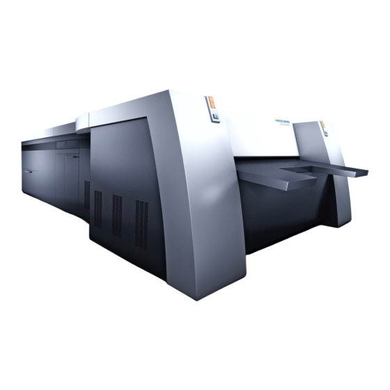
162/190 are described in the installation instructions of the components. Suprasetter 145/162/190 Fig. 1 Suprasetter 145/162/190 as a semi-automatic device (basic machine consisting of imaging unit and plate loader) • (1) Imaging unit (BBE) The imaging unit (Fig. 1/1) contains the imaging drum with a diameter D = 492 mm. Imaging of the plates is done by a maximum of 11 laser modules at a rotational speed of up to 380 rpm. -
Page 42: Access To The Components
Note: If the Suprasetter is shipped as a fully automatic device with APL, cover plates are used instead of a rear panel (Fig. 3/1). During refitting of the device, the rear panel must be replaced by cover plates (see "Suprasetter 145/162/190 with APL", page 116). - Page 43 (distance approx. 720 mm) of the two levels, for example to perform work on the components at the front edge of the table. Fig. 5 Imaging unit and plate loader, access open Suprasetter 145/162/190 – Installation...
- Page 44 Access to Machine Components At the front edge, you find the following compo- nents on each side (i.e. 2 off) • a carriage driven by a toothed belt, transport- ing printing plates, • a stepping motor driving the toothed belt and consequently the carriage, •...
-
Page 45: Installation Preparation
Indentation hardness 80-100 N/mm² Tab. Floor stability The floor (covering) must have an abrasion-proof, easy-to-clean, smooth surface, it must be antistatic and meet the following quality requirements: Suprasetter 145/162/190 – Installation... -
Page 46: Machine's Arrival At The Customer's
Installation Preparation ≤ 500 V/cm Max. charge ≤ 30 sec Half-life period ≤ 10 Ω Leakage resistance ≤ 10 Ω Volume resistance Tab. Electrical floor properties During installation, make sure that the device is installed at a sufficient distance from walls and other objects to ensure adequate ventilation and quick servicing. -
Page 47: Protection Against Corrosion
Note: The accessories kit is located at the bottom of the plate loader. Protection Against Corrosion All HEIDELBERG machines are coated with VCI corrosion protection and sealed with PVC foil prior to shipment. Underneath the foil a special atmosphere forms that protects the machine against corro- sion. -
Page 48: Plate Material
Installation Preparation Entry point (Fig. 2) for power cable and com- pressed air. Fig. 2 Power cable and compressed air Plate Material Depending on the printing plate manufacturer and the used plate material, thermal plates are also sensitive to light. The quality of some plates may degrade even after a few minutes due to the UV por- tion of white light illumination in the room. -
Page 49: Special-Purpose Tools
Laser module • Adapter for service terminal Cable for connecting a PC to the Suprasetter. For servicing only. Fig. 4 Adapter for service terminal Description Adapter cable PC - X113 Part number PR.581.7293/01 Usage Service monitor connection Suprasetter 145/162/190 – Installation... - Page 50 Installation Preparation • Spirit level Accuracy 0.05° Model, e.g. Bosch DNM 60 L Fig. 5 Spirit level Description Electronic spirit level Part number 00.894.1437/ Application Adjustment • Hold-to-Run Button The hold-to-run button lets you watch the move- ments of exposure table and lift tables while the covering is open.
-
Page 51: Overview: Chassis Alignment
3. Opto Switch Adjustment Move both opto switches in the plate loader to the imag- ing unit. 4. Connecting the Units Finally, the units are interconnected with 0.3 mm sheets on the floor sheets. Suprasetter 145/162/190 – Installation... -
Page 52: Setting Up The Units
Installation Setting up the Units Setting up the Imaging Unit Delivery of the imaging unit with a fork-lift truck. Remove wrapping foil. Remove all side coverings. Remove the table. Remove the front covering. Remove the transport safeguards (Fig. 1/1) that fasten the Suprasetter to the pallet. - Page 53 Risk of injury from falling device/tilting fork-lift truck If the forks of the fork-lift truck are not centered in position, there is a risk of the fork-lift truck or device tipping over. Position the forks in the middle underneath the Suprasetter Suprasetter 145/162/190 – Installation...
- Page 54 Installation Lift the Suprasetter off the pallet with a fork-lift truck. Fig. 5 Fork-lift truck Note on positioning: Heed lateral clearances, all other components are aligned to the Suprasetter. Position the Suprasetter with a hand-lift truck. Fig. 6 Positioning Note: Be careful when adjusting the height of the machine base since all further height adjustment refers to the machine base.
- Page 55 Heed the sequence: 1. front right 2. rear right 3. front left 4. rear left Fig. 8 Leveling After aligning the imaging unit, lock the screws (Fig. 9/1) on all 4 feet. Fig. 9 Locking Suprasetter 145/162/190 – Installation...
- Page 56 Installation Undo the screws (Fig. 10/1 M6x50) on all 4 recorder feet and remove them. They were used as transport safeguards to link machine base and chassis. Leave the two centering bolts (Fig. 10/2) in the rear feet. Screw down all four chassis feet (Fig. 11/1) until they make contact.
-
Page 57: Remove The Remaining Transport Safeguards
Fig. 14 Transport safeguards, dust hood left Transport safeguard, dust hood right: Unscrew the 6 screws of the transport safeguard and remove the bracket (Fig. 15/1) and the plate inside the dust hood (Fig. 15/2). Fig. 15 Transport safeguard, dust hood right Suprasetter 145/162/190 – Installation... - Page 58 Installation Remove the two cable ties (Fig. 16/1) each on the left and right side. Fig. 16 Transport safeguard, bridge Only with the Exhaust option: Remove the foam rubber pad (Fig. 17). Fig. 17 Transport safeguard, exhaust distributor Only with the Exhaust option: Cut the cable ties (Fig.
- Page 59 After the screw (Fig. 20/1) is fit back on again, the coolant hose (Fig. 21/1) must be secured at this position (Fig. 21 /2) with an additional cable tie (is attached loosely to the coolant hose). Fig. 21 Additional cable tie Suprasetter 145/162/190 – Installation...
- Page 60 Installation Transport safeguard, cable chain: Unscrew the 3 screws of the transport safeguard and remove the bracket (Fig. 22/1). Fig. 22 Transport safeguard, cable chain Transport safeguard, carriage: Unscrew the 2 screws of the transport safeguard and remove the bracket (Fig. 23/1). Take out the screw (Fig.
- Page 61 Fig. 26 Transport safeguard, balancer weights right CAUTION Beware of moving parts in the Suprasetter The VCT bar slips down when the lock screws Fig. 27/2 and Fig. 28/2 are removed. Do not grasp below the VCT bar. Suprasetter 145/162/190 – Installation...
-
Page 62: Plate Loader
Installation VCT (= Vacuum Channel Terminator) transport safeguards, rollers: Cut open and remove the cable tie (Fig. 27/1) securing the transport roller . Unscrew and remove the screw (Fig. 27/2) secur- ing the VCT bar. Unscrew the 4 screws of the transport safeguard (Fig. - Page 63 Fig. 30 Transport safeguard, door Unscrew the three screws (Fig. 31/1) and remove the transport safeguard (Fig. 31/2) (not applicable on manual machine). Fig. 31 Transport safeguard, online connection right Suprasetter 145/162/190 – Installation...
- Page 64 Installation Unscrew 4 screws of the transport safeguard, take out the 4 respective tenon blocks and the holder (Fig. 32/1). Fig. 32 Transport safeguard, plate loader Undo 6 screws of the transport safeguard and remove the bracket (Fig. 33). The bracket is located below the online connection (Fig.
- Page 65 (Fig. 36/2)(not applicable on manual machine). Fig. 36 Transport safeguard, online connection left Unscrew 4 screws of the transport safeguard, take out the 4 respective tenon blocks and the holder (Fig. 37/1). Fig. 37 Transport safeguard, plate loader Suprasetter 145/162/190 – Installation...
- Page 66 Installation Undo 6 screws of the transport safeguard and remove the bracket (Fig. 38). The bracket is located below the online connection (Fig. 37/2) Fig. 38 Transport safeguard, plate loader Undo 4 screws of the transport safeguard and remove the bracket (Fig. 39). Remove the two tenon blocks identified by an arrow in the figure.
- Page 67 (Fig. 43/2) to the outside. The electrical connections are located at the top end underside of the guide plates (Fig. 43/3). Fig. 43 Guide plates Suprasetter 145/162/190 – Installation...
- Page 68 Installation Push the plate loader close to the recorder. The centering mandrel (Fig. 44/1) on the left side must positively engage at the recorder, and the block must make contact on the other side. Fig. 44 Centering mandrel Adjust the feet until the height at the chassis is flush with the recorder;...
- Page 69 The spindles must be removed again after posi- tioning because the chiller cannot be moved if this is not done. Fig. 47 Plate Suprasetter 145/162/190 – Installation...
-
Page 70: Chiller Connection
Installation Chiller Connection CAUTION Risk of injury from liquid hazardous to health Heed the handling notes given in the safety data sheet for the coolant. Collect spilt liquid. Remove both screws (Fig. 48/1). Lower the front rollers of the chiller. To do this, first loosen the two screws (Fig. - Page 71 Installation Plug in connectors RS232 (Fig. 50/1) and XP (Fig. 50/2) at the rear. Fig. 50/3: Power cable inlet Fig. 50 Connections Remove 8 screws (Fig. 51/1) and take off the cov- ering. Fig. 51 Cover Suprasetter 145/162/190 – Installation...
- Page 72 Installation Guide the power cable (adapter PG.147.6008 from the BBE) through the PG gland (Fig. 52). The PG gland (Fig. 50/3) serves as EMC connec- tion. The clamping sleeve (Fig. 52/1) must be in contact with the power cable screen. Guide in the power cable and add clamping sleeve (Fig.
-
Page 73: Establish Connections
(Fig. 55/1) and the plate loader; to do so, loosen the sheet metal, turn it and fasten it with 6 screws again. Fig. 55 EMC connection between imaging unit and plate loader Suprasetter 145/162/190 – Installation... -
Page 74: Data Cable To Plate Loader
Installation Data cable to plate loader Unpack the connection lines in the plate loader. Fig. 56 Connection lines in the plate loader Remove the screws (Fig. 57/1) in the plate loader and take off the cover (Fig. 57/2). The cables will be routed through the cable duct to the recorder from behind. -
Page 75: Plate Loader Power Connection
Fasten the PE wires (Fig. 60/4) of the cables with screws. Fig. 60 Terminal block in the plate loader with Lexium 05 Secure pairs of single wires of the power cable with cable ties at a distance of 20 mm to the ter- minal. Suprasetter 145/162/190 – Installation... -
Page 76: Lexium 32 (3-Phase)
Installation Fasten the cover with five screws (Fig. 61/1). Fig. 61 Cover in the plate loader with Lexium 05 Lexium 32 (3-phase) Open the door of the plate loader's electronics cabinet. Remove the front cover plate of the power supply for the control unit of the lift table. -
Page 77: Lexium 32 (3-Phase + N)
EMC shielding (see Fig. 66). Fig. 65 Terminal block in the plate loader with Lexium 32, 3-phase + N Note: Cable (Fig. 65/7) on X400b (Fig. 65/1) with cable clamp and PE cable only with APL. Suprasetter 145/162/190 – Installation... -
Page 78: Secure The Cover Plate Above The Power Supply
Installation Secure the cover plate above the power supply Secure the front cover plate above the power supply: 14x M4 combination screws, 2x M4 nuts with washers (arrows: attachment on shipment) Fig. 66 Screws on the cover plates of the power supply box... -
Page 79: Plate Loader Compressed Air
Plate loader compressed air Route the compressed air connection (8 mm Ø) from the imaging unit to the valve block in the plate loader and attach it (Fig. 67/1). Fig. 67 Compressed air connection in the plate loader Suprasetter 145/162/190 – Installation... -
Page 80: Data Cable To Imaging Unit
Installation Data cable to imaging unit Connect X232 of the safety loop from the plate loader to the rear of the electronics box (Fig. 68/ 232). Fig. 68 Safety loop in the imaging unit Connect X190 of adapter PG.147.7001 to ACRB-RCI (Fig. -
Page 81: Imaging Unit Power Supply
The strain reliefs can be found in the accessories kit. Fig. 71 Strain relief Remove the two screws (Fig. 72/2), insert the strain relief (Fig. 71) and fasten it with the two screws again. Fig. 72 Strain relief Suprasetter 145/162/190 – Installation... - Page 82 Installation Remove the two screws (Fig. 73/2), insert the strain relief (Fig. 71) and fasten it with the two screws again. Fig. 73 Strain relief Power supply box Lexium 05 Unscrew the 16 screws of the cover (Fig. 74/1) above the power supply box. One screw is only accessible through the hole (Fig.
- Page 83 Fig. 76 Pairs of single wires with cable ties Power supply box Lexium 32 Secure the front cover plate above the power supply: 16x combination screws (arrows: attachment on shipment) Fig. 77 Screws on the cover of the power supply box Suprasetter 145/162/190 – Installation...
- Page 84 Installation Loosen and pull off connectors (Fig. 78/1, 3x) Unscrew the 4 screws of the cover (see Fig. 77) above the power supply box. Lift out and put aside the cover of the power sup- ply box carefully (because of the cables Fig. 78/1). Fig.
-
Page 85: Plate Loader Opto Switches
Take the two opto switches on the right (Fig. 81/1) and left side of the plate loader out of their trans- port position and attach them as shown with the two screws. Fig. 81 Opto switches between imaging unit and plate loader Suprasetter 145/162/190 – Installation... -
Page 86: External Compressed Air Connection
Installation External Compressed Air Connection Connect external compressed air in the imaging unit and set the pressure to 6-8 bar with the adjusting valve (Fig. 82/1). Fig. 82 Compressed air in the imaging unit Note: The external compressed air (Fig. 82/3) is connected using a commercially available coupling component (Fig. -
Page 87: Laser Module Installation
Sensitive lens Do not touch the lenses! Take the laser module out of the packing. Check that the electric contacts are undamaged. Pull the plugs (Fig. 83/1) out of the connectors. Fig. 83 Laser module with plugs Suprasetter 145/162/190 – Installation... -
Page 88: Hose Connections
Installation Connect the hoses (Fig. 84/1). Fig. 84 Laser module with hoses Hose connections Note: Trim down the hose end straight if a used hose shows collet traces. Push hose (Fig. 85/5) into the hose connector (Fig. 85/1) until the resistance of the collet (Fig. 85/3) can be felt. - Page 89 Fig. 87 Laser module with spring Take eccentric (Fig. 88/1) from the package, mount it on insertion tool BV.011.9825 and screw tight. Fig. 88 Eccentric and insertion tool NOTICE Risk of breakage Do not use force; the pin could break! Suprasetter 145/162/190 – Installation...
- Page 90 Installation Guide the eccentric (Fig. 89/3) with the pin upwards through the (right) hole (Fig. 89/1) and hook the pin (Fig. 89/2) into the eye of the spring hanging down. Tighten the spring by turning the large wheel of the insertion tool by approx.
- Page 91 Note: Connector X380 must not be fitted if a slot is not occupied by a laser module. Open the housing and check if connector X380 (Fig. 92/1) is fitted (not necessary for fitting according to the machine data sheet). Fig. 92 Connector X380 Suprasetter 145/162/190 – Installation...
-
Page 92: Imaging Unit: Laser Module Slots
Fig. 93 Marking of slots Depending on the configuration, all laser modules must have the same distance to each other. The following tables show all possible module configu- rations for Suprasetter 145/162/190: Fig. 94 Laser Module Slots Module configuration Suprasetter 145: Slot... -
Page 93: Pc Connection
Close the PC again. Fig. 95 PC inside Plug in the GBit and GUI cables (Fig. 96/1) at the rear of the PC and route them to the electronics box of the imaging unit. Fig. 96 PC rear Suprasetter 145/162/190 – Installation... - Page 94 Installation Connect GBit X309 (Fig. 97/2) and GUI X171 (Fig. 97/1) in the electronics box. Fig. 97 GBit and GUI in the imaging unit...
-
Page 95: External Power Supply
Installation External Power Supply If the Suprasetter 145/162/190 is to run with additional components like ACL, APL or cross conveyor, these components must be installed and connected to the Suprasetter before the Suprasetter is connected to the power supply. Establish external power supply to the Suprasetter. When doing so, observe the specifications for... - Page 96 Installation Public utility Customer Suprasetter F-Net 3 Phase Delta Delta to Wye (Star) Transformer (10KW) (Corner Ground) 4-wire Phase - Phase: 400V Phase - Phase: 220V or 440V or Phase - Neutral: 230V 480V or xxxV Tab. F-Net Tab. F-Net * see local standard.
- Page 97 Customer Suprasetter G-Net 3 Phase Delta (Stinger) Delta to Wye (Star) Transformer (10KW) 4-wire Phase - Phase: 400V Phase - Phase: 240V or xxxV Phase - Neutral: 230V Tab. G-Net Tab. G-Net * see local standard. Suprasetter 145/162/190 – Installation...
-
Page 98: Software
Installation Software Network Adapter Configuration Connect the terminal cable to a COM port of the PC if a terminal is present . Install Prinect Shooter, CTP User Interface and DIAG on this PC. The operating system will detect new hardware when the PC is switched on for the first time. - Page 99 "Update Driver". Fig. 101 Select Ethernet controller The Hardware Update Wizard now opens (Fig. 99). Choose "No, not this time" and click "Next". Choose "Install from a list or specific location (Advanced)". Fig. 102 Hardware Update Suprasetter 145/162/190 – Installation...
- Page 100 Installation Click the bottom option and choose the driver yourself. Fig. 103 Installation Options Choose "Network adapters". Fig. 104 Choose hardware Select "INTEL" as manufacturer. Click the network adapter of the supplied card and continue with "Next". Download the driver from the manufacturer's homepage if the network adapter does not appear in the list.
- Page 101 Fig. 107 Software installation The card appears in "Network adapters" after you have closed the Device Manager. All network adapters not used must be disabled. Install the Multimedia Controller in "Other devices" during GUI installation. Fig. 108 Network Adapters Suprasetter 145/162/190 – Installation...
- Page 102 Installation Select the network. Fig. 109 Network Choose Network Connections and select the "Local Area Connection x" matching the installed card. Fig. 110 Network Connection Also enable "Show icon in notification area when connected". Fig. 111 LAN Connection 2 Properties...
- Page 103 Click "Properties" and specify the IP address. Fig. 112 IP address Rename "Connection x" to "Suprasetter". Fig. 113 Rename to Suprasetter Select the new item and choose "Advanced Set- tings..." in the "Advanced" menu. Fig. 114 "Advanced Settings..." Menu Suprasetter 145/162/190 – Installation...
- Page 104 Installation Choose "LAN-In-house" under "Connections" and click the arrow buttons to the right to make it the first row in the list, then press "OK". Fig. 115 Network Connection After a PC reboot, the Suprasetter will appear if it is switched on. Fig.
-
Page 105: Installing Recorder Software
In addition, the USB stick contains the parameter database as delivered as "data_all.txt". Fig. 118 Affixing of the USB stick Suprasetter 145/162/190 – Installation... - Page 106 Installation NOTICE It is vital to use only the software shipped on the USB stick for installation of the Suprasetter! If incorrect software is used, there is the risk that the parameters of the database will be lost or the Suprasetter damaged! The software comprises the two Windows applications CTP User Interface and DIAG as well as the recorder software and Speedway Control Manager.
-
Page 107: Filling The Chiller
Mixing ratio: Glysantin: chlorine-free drinking water = 1:2 Top up coolant until the Max mark (Fig. 120/1) is reached (approx. 21 liters). The coolant volume for the entire system is approx. 50 liters. Fig. 120 Max mark Suprasetter 145/162/190 – Installation... - Page 108 Installation Note by the Glysantin manufacturer: "Clean water that is not too hard must be used in the preparation of the coolant. If an analysis of the water shows that the values exceed the limits in the table, then the water must be prepared ade- quately, for example, by adding soft, distilled or fully desalinated water.
-
Page 109: Configuring And Testing The System
Run the following DIAG tests (in this order) and determine the parameters: • 159 • 151 • 152 • 154 • 155 • 158 For details about the DIAG tests, see the Online Help of the diagnostics software. Suprasetter 145/162/190 – Installation... -
Page 110: Testing
Installation Testing Following installation, you must run the programs of the Material and System Wizard in the CTP User Interface. Operation of the programs and testing instructions for plates are described in the Online Help of the user interface of the Suprasetter in the "Material Wizard" window. chapter in the service manual describes how to test printing plates. - Page 111 Attach the tread plate (Fig. 126/1). The tread plate is in the accessories kit located at the bottom of the plate loader when shipped. Fasten all coverings in the machine with screws. Fig. 126 Inner coverings Suprasetter 145/162/190 – Installation...
-
Page 112: Check Tension Of Drive Toothed Belt On Imaging Unit
Installation Loosen the bracket (Fig. 127/1) and align the hous- ing elements with a spirit level. The dust hoods must be centered and parallel to each other. The gaps should be identical on both sides. Heed a gap of 6 mm. Any connectors of the safety switches that have to be moved after the side panels are fitted back on must be sealed again with sealing varnish... - Page 113 Tighten the nut (Fig. 129/1) and check the belt ten- sion again. Tighten the screws of the motor block fixture. Turn the support screw so that it contacts the motor block and then turn another 1/4 turn. Check the belt tension again. Suprasetter 145/162/190 – Installation...
-
Page 115: Optional Components
This difference must be tested with a measuring device and, if necessary, set. You can set the conveying speed of the OLP con- veyor using controls R1 and R2 on the OLP con- veyor (see following table). Fig. 3 Speed on OLP conveyor Suprasetter 145/162/190 – Installation... -
Page 116: Cross Conveyor
Optional Components Control Route Speed up to sensor on the OLP conveyor Adjust to recorder output speed Speed as of sensor on the OLP conveyor Adjust to speed of the connected finishing device Cross Conveyor Heidelberger Druckmaschinen AG recommends the Nela cross conveyor (see also Nela documenta- tion for cross conveyor) as the transfer unit when an online processor is to be connected. - Page 117 Remove the cover from the connector panel in the recorder and route the data cable into the recorder from below. Plug on connector X196 (Fig. 7/1) and reattach the cover. Fig. 7 Data cables Suprasetter 145/162/190 – Installation...
-
Page 118: Suprasetter 145/162/190 With Apl
Rollers of the cross conveyor Flat belts of the cross conveyor Suprasetter 145/162/190 with APL The rear panel of the plate loader must be removed and replaced by two cover panels if the Supra- setter 145/162/190 is retrofitted with the APL autoloader. - Page 119 (Fig. 10/1) and close the terminal (Fig. 10/1) with a dummy plug (Fig. 10/2). Connect the compressed air hose of the imaging unit to the compressed air hose of the APL with the adapter (Fig. 11/1). Fig. 11 Compressed air connection Suprasetter 145/162/190 – Installation...
- Page 120 Optional Components 2. Safety loop Pull the jumper connector off X432 (Fig. 12/1) and connect the safety loop of the APL. Keep the jumper connector at the machine. Fig. 12 Safety loop 3. Data connection Note: Route the cables together with the cable harness out of the plate loader; if necessary, remove the covers to do this.
- Page 121 5. Cover panels in the plate loader (Mod Kit 1039H, PG.995.016N) WARNING Electric shock hazard and hazard of being crushed by moving parts! The Suprasetter 145/162/190 may not be operated with the APL if the cover pan- els replacing the rear panel are not fitted properly. Suprasetter 145/162/190 – Installation...
- Page 122 Optional Components Fig. 15 Cover panels on the plate loader Insert tenon blocks (Fig. 15/4) into the profiles and secure each of the cover panels (Fig. 15/1) with eight screws (Fig. 15/2) and washers (Fig. 15/3). Fit the side panels of the plate loader again. After the Suprasetter and APL are started, create the network connection between the machines.
- Page 123 6. In the "CTP User Interface" in "Tools" (Fig. 16/1), activate "Enable Recorder Terminal" and open the recorder terminal (Fig. 16/2). 7. Enter your password and confirm the dialog with "OK" (Fig. 16/3). Fig. 16 Enable Recorder Terminal Suprasetter 145/162/190 – Installation...
- Page 124 Optional Components 8. In the "Main Menu", enter "4" for "Record Menu". 9. In the "Record Menu", enter "0" for "NV Memory Base Menu". 10. In the "NV Memory Base Menu" enter "4" for "Browse Data". Fig. 17 Main Menu in the Terminal Program 11.
- Page 125 21. After that, you will see a message, informing you that the system configuration was changed and the GUI must be restarted. After you confirm this message, the GUI exits automatically and you can then restart it. Suprasetter 145/162/190 – Installation...
-
Page 127: Technical Data
Technical Data Technical Data Technical Data of Suprasetter 145/162/190 Type Value Comment Dimensions 3400 mm x 3380 mm x 1560 mm, WxDxH manual 3400 mm x 3380mm x 1560 mm, WxDxH, semi-automatic machine 3400 mm x 1836 mm x 1560 mm... - Page 128 Comment Noise emission < 70 dB (A) Workplace-related value Plate size max. 1425 mm x 1460 mm Suprasetter 145 max. 1425 mm x 1630 mm Suprasetter 162 max. 1425 mm x 1905 mm Suprasetter 190 min. 500 mm x 650 mm Plate thickness 240 µm to 400 µm...
-
Page 129: Index
Protective conductor connection 8 PVC foil Temperature balance 45 Radio interference suppression 15 Remote Control 34 Safety 7 Heidelberg Remote Service 34 Safety labels 20 Safety loop 15 Service switch 17 Site and floor properties 43 Special-purpose tool 47 Suprasetter 145/162/190 – Installation... - Page 132 Fax +49 6221 92-6999 www.heidelberg.com Trademarks Heidelberg, the Heidelberg logotype, Prinect, Suprasetter and Speedmaster are registered trade- marks of Heidelberger Druckmaschinen AG in the United States and other countries. Adobe and PostScript and Acrobat are either registered trademarks or trademarks of Adobe Systems Incorporated in the United States and/or other countries.
Need help?
Do you have a question about the Suprasetter 145 and is the answer not in the manual?
Questions and answers