Table of Contents
Advertisement
Advertisement
Table of Contents
Troubleshooting

Subscribe to Our Youtube Channel
Related Manuals for HEIDELBERG mPG 501


Summary of Contents for HEIDELBERG mPG 501
- Page 1 User Guide PG 501...
- Page 2 PG 501 Doc. No.: DWL-HI-049 Revision: 5 (Feb 2014) Copyright © 2014 by Heidelberg Instruments User Guide...
-
Page 3: Table Of Contents
PG 501 Table of Contents Table of Contents ......................iii Preface ..........................1 Conventions used ..................... 1 Safety Information ..................... 1 Related Documentation .................... 1 Contact ........................2 System Description ......................3 System Startup and Shutdown ..................5 Startup ........................5 Shutdown ........................ -
Page 5: Preface
RELATED DOCUMENTATION Heidelberg Instruments offers further manuals related to the machine and its operation. If you did not get one of these or need an update, please contact Heidelberg Instruments Mikrotechnik, Germany. System requirements, sizes and weights of Pre-Installation Guide components etc. -
Page 6: Contact
Fax: +1-310-212-5254 Korea: Heidelberg Instruments Service Korea #316 Expo Officetel, 381 Mannyeon-dong, Seo-gu Deajeon 302-834 South Korea Phone: +82-42-482-1668 Fax: +82-42-482-1669 You can also reach Heidelberg Instruments via e-mail: service@himt.de, or visit our site on the Internet: http://www.himt.de User Guide... -
Page 7: System Description
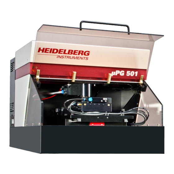
PG 501 System Description The µPG 501 lithography system consists of the lithography unit and a control PC. Figure 1: µPG501 lithography unit front side 1 - Cover lid with interlock circuit 2 - System base 3 - Stage 4 - Vacuum field adjustment screws 5 - Vacuum switch 6 - Write head 7 - Vacuum and compressed air supply lines... - Page 8 PG 501 Figure 2: µPG501 lithography unit back side 12 - Ventilation slits (positions vary) 13 - Lithography unit power connector and On/Off switch 14 - Heat exchanger of LED water cooling circuit 15 - Compressed air connector (quick connector) 16 - USB connector for DMD data 17 - Network connector for LAN 18 - Compressed air regulation stage...
-
Page 9: System Startup And Shutdown
PG 501 System Startup and Shutdown NOTICE: Updates of driver software can inhibit the µPG 501 from working properly. • Whenever Windows offers updates, only select important updates • Never change the settings for automatic updates to fully automatic. STARTUP 1. -
Page 10: Design Data
PG 501 Design Data The µPG 501 can expose designs defined in several different formats. Each of these formats is implemented for different purposes: o DXF, GDSII, Gerber: Standard formats for binary (2 dimensional) designs o CIF: Caltech Intermediate Form, easy-to-use language for direct definition of binary (2D) structures in a text file. -
Page 11: Exposures
(e.g., chromium-oxide) • for direct writing on wafers: o silicon wafers (for other wafer types, please contact the Heidelberg Instruments Customer Support on information if they are usable at all, and recommendations on exposure and processing) o size between 2”... -
Page 12: Exposure Procedure
PG 501 coating and processing procedures (e.g. spinning speed, pre-bake and post-bake parameters, recommended developer and developing time etc.). General Advice: • Take care to protect the substrates from light (even safe light, as far as possible) and humidity at all times until developing is finished. •... - Page 13 PG 501 Once the startup sequence is finished and no error has occurred, the wizard automatically moves on to the next panel. If it is necessary to view the messages created during startup, the first screen can be reached anytime by clicking the Back button(s).
- Page 14 PG 501 Alignment Pins Vacuum Setting (plate / wafer) small plate: 2" / 2.5": 3": 4": 5": Figure 5: Alignment pins placement and vacuum region selection according to substrate size User Guide...
- Page 15 PG 501 5. Make sure the resist coated side of the substrate is turned up, and position it against the alignment pins. If the substrate bears alignment marks that should be used for exposure, note that the coordinate system of the stage is oriented such that the x axis corresponds backward-forward...
- Page 16 PG 501 C Exposing 1. In the panel, parameters have Expose to be set that depend on the substrate type that is used. • Exposure Time: There are two parameters that influence amount of energy that is deposited in the resist. While the output power of the LED is usually fixed to 100% (can be adjusted during installation according to the requirements of...
- Page 17 PG 501 NOTICE: Manual focusing while this function is active can lead to irreversible damage to the system. Don’t use any focusing functions before the freezing is deactivated. 4. Check again if air pressure is OK, the lid is closed, and no alignment pins have been left in the stage chuck.
- Page 18 PG 501 STEPS OF AN EXPOSURE WITH ALIGNMENT Alignment is done to expose a design in a defined position with respect to marks on the substrate. The coordinates of a clearly defined point within a mark (e.g., a corner) are used as anchor(s) for the coordinate system.
- Page 19 PG 501 A Exposure Setup 1. Prepare the design in the required format, as described in the Conversion Software Manual. Make sure the design complies with all design rules given there, the general as well as the specific. 2. If the design is not accessible via network from the Menu PC, transfer it to the µPG 501 PC e.g., using a memory stick or CD.
- Page 20 PG 501 Check the design parameters listed in the window to make sure the design was converted with the correct parameters. B Substrate Loading 1. Make sure the cover lid (1) is closed (interlock lamp (10) off) and the compressed air is present. 2.
- Page 21 PG 501 9. The next message box offers to set the current position as coordinate origin. Click OK. 10. In the Exposure Mode frame, click on the checkbox for Alignment. 11. Click Next to proceed to the next panel. C Alignment Procedure In the panel, a text box on the Alignment...
- Page 22 PG 501 • If a certain feature in the camera field should be moved to the center, click on the cross hair button in the center of the button field, position the crosshair in the image and then click again on the button. •...
- Page 23 PG 501 13. If necessary, adjust the position of the crosshair / position and size of the area of interest box. Template Matching: If the previous template was saved, it is possible to simply Re-Use it by clicking the button. Otherwise, define and save a new template in the same way as before, or use the Load Template function to load a different template.
- Page 24 PG 501 For both exposure time and defoc(us), the Exposure Wizard contains a function to easily set up and run test exposure series. Please refer to the section on exposure optimization below for more information. 2. For small substrates that should be exposed up to the very edges, the option Freeze AutoFocus can be activated.
- Page 25 PG 501 STEPS OF A TARGET MODE EXPOSURE With target mode exposures, it is possible to expose boxes of arbitrary length and width limited only by the camera field size directly on a substrate, without need of a design and conversion. This can be used e.g., to create connections between structures, or to interrupt them.
- Page 26 PG 501 • Make sure the substrates comply with the specifications of the µPG 501 (Size between 2” and 5”, max. thickness 6mm, flatness tolerance < ± 20µm) • Never use out-of-date substrates. • Do not use substrates with scratches on top or bottom, visible contaminations in the resist, or non-uniform resist distribution in the area to be exposed.
- Page 27 PG 501 C Target Mode Exposure Preparation In the panel, a text box on Target Mode the right leads through all steps of alignment setup. steps nevertheless also described here. 1. Click on Start Target Mode. Note: Anytime during alignment, clicking Cancel Target Mode resets the procedure.
- Page 28 PG 501 5. A box for marking an area of interest appears in the camera image field. If a new exposure area should be defined, move and shape the box to mark the area that should be exposed. If a previously defined box should be loaded, press Load Box.
- Page 29 PG 501 E Unloading 1. After exposure is finished, if no further designs should be exposed on the same plate, click on Unload. 2. Wait until all movement has stopped. 3. Open the lid, switch off the vacuum with the vacuum switch (5) and carefully lift the substrate off the chuck.
-
Page 30: Substrate Processing
PG 501 SUBSTRATE PROCESSING The steps of processing of a substrate are: • Post exposure bake: Depending on application and resist type, a post exposure bake of the exposed substrate on a hot plate or in an oven may be required. Refer to the resist manufacturer’s documentation for specific information on this. - Page 31 PG 501 • Stripping: After etching and rinsing, the remaining resist is removed. This can be done by use of a solvent or stripper, or by exposing the resist with a UV lamp (for thin layers e.g., a facial tanner can be used for 10 minutes – ½ hour), and using the undiluted developer on it afterwards.
-
Page 32: Exposure Optimization
PG 501 Exposure Optimization For optimum exposure results, the correct energy and defocus for a substrate type has to be determined. To avoid having to do many single exposures with manually changed values, the register card Series in the offers fast setup of Control Panel exposure series... - Page 33 PG 501 5. On the left, select the distances between the fields. If only one series was selected, only a step size in x can be entered. If Both Series was selected, also a step size in y is required. The size of the design selected for exposure is shown below the text boxes for reference.
-
Page 34: Tools Menu
PG 501 Tools Menu The Tools menu in the main menu bar of the Exposure Wizard gives access to some additional functions for troubleshooting and optimization of system performance. INITIALIZE STAGE The function Tools Initialize Stage re-initializes the stage by moving it into the end switches, where the universal coordinate system is zeroed. - Page 35 PG 501 absolute movement) and click on the arrow beside the fields. Keep in mind to use the correct signs. The stage moves directly to the distances / coordinates given. Write head functions The XY Stage register card also contains controls for write head movement. During standard operation, these functions are never required, as the write head is always moved automatically in conjunction with the process step that is being done.
-
Page 36: Troubleshooting And Maintenance
This section contains advice on some possible problems that might be encountered during operation of the µPG 501. If you encounter a problem that cannot be solved in this way, please contact your Heidelberg Instruments service office (see section Contact in the preface). -
Page 37: Exposure Result Problems
PG 501 - system is not well leveled Remedies: - check air pressure (see system installation instructions on required values) - check on interlock lamp before starting a new exposure - reset stage (menu Tools Initialize Stage) - check and improve leveling as described in the system setup section EXPOSURE RESULT PROBLEMS Problem: Plate is blank... -
Page 38: Advanced Troubleshooting
PG 501 Remedies: - check design - check wizard entries Problem: Design looks completely mixed up Possible causes: - vacuum off Remedies: - check vacuum pump and vacuum on stage Problem: Design stretched or shrunk compared to previous layer Possible causes: - previous layer not exposed with µPG, coordinate system units do not match Remedies: - shrink or stretch design to compensate... -
Page 39: Fuses
PG 501 FUSES Types and locations of fuses used in the µPG 501: To the right of main power line: 6.3 A time delay container with 6.3 A time delay fuse Figure 20: 6.3 A time delay fuse at Lithography Unit back side MAINTENANCE Cleaning The system covers and internal surfaces should be cleaned occasionally to avoid... - Page 40 PG 501 Notes User Guide...
- Page 41 PG 501 Notes User Guide...
- Page 42 PG 501 Notes User Guide...
Need help?
Do you have a question about the mPG 501 and is the answer not in the manual?
Questions and answers