
Subscribe to Our Youtube Channel
Related Manuals for Lamtec F300K Series


Summary of Contents for Lamtec F300K Series
- Page 1 Manual F300K Compact Flame Scanner Sensors and Systems for Combustion Engineering www.lamtec.de...
-
Page 3: Table Of Contents
Table of Contents Table of Contents Important Information about the Manual ........5 Purpose/Applicability of the Document . - Page 4 Table of Contents Electrical Connection ........... 32 Putting the Device into Operation for the First Time .
- Page 5 Table of Contents Repairs ..............81 Correcting Faults .
-
Page 6: Important Information About The Manual
Important Information about the Manual Important Information about the Manual Purpose/Applicability of the Document This manual enables users to handle the F300K compact flame scanner system safely and efficiently. The manual is valid for all F300K systems in any configuration. The information in this document applies to software version F300K V1.3.0.0 and User Inter- face V1.4.0.0. -
Page 7: Target Group
Important Information about the Manual Target Group These instructions must have been read carefully and completely before commencing with any work. The basic prerequisite for working safely is compliance with all the specified safety instructions. NOTICE All assembly, commissioning, troubleshooting and maintenance work may only be carried out by authorised and trained personnel. -
Page 8: General Safety Instructions
General Safety Instructions General Safety Instructions Classification of the Safety Instructions and Warnings The following symbols are used in this document to draw the user's attention to important safe- ty information. They are located at points where the information is required. It is essential that the safety information is observed and followed, and that applies particularly to the warnings. -
Page 9: Product Safety
General Safety Instructions Product Safety WARNING! This product is state-of-the-art technology and complies with the generally accepted safety-related rules and regulations. Every device is tested before delivery to ensure that it is working properly and safely. Only use this product when it is perfect condition and in accordance with the manual, the prevailing regulations and guidelines and the applicable safety and accident prevention regulations. -
Page 10: Product Description
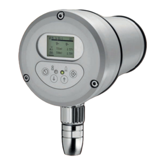
Product Description Product Description Structure of the F300K 1 Lens holder 2 F300K housing 3 Cover with operating unit UI (user interface) or LED display 4 Device connector 5 Connecting cable Fig. 3-1 The components of the F300K... -
Page 11: Basic Variants
Product Description Basic variants There are two basic variants of the F300K NOTICE The basic functions of the variants are identical. The differences lie merely in how they are operated and their displays. F300K with LED display Fig. 3-2 F300K display unit with LED display LEDs in the display strip show the intensity of the flame: a series of two yellow and three green LEDs;... -
Page 12: Life Cycle
Product Description F300K with user interface Display LED shines red: Flame OFF/ready for operation LED flashes red: fault LED shines green: flame ON LED flashes green: warning ENTER key UP key DOWN key ESC/BACK key Fig. 3-3 F300K operating and display unit with UI Life Cycle The device is designed to have a service life of 10 years or 250,000 cycles. -
Page 13: Rating Plate
Product Description Rating Plate Fig. 3-4 Position of the rating plate T = position of the type plate On the rating plate you will find information on the configuration of your flame sensor: Rating plate example:... -
Page 14: Selection Criteria
The spectral sensitivity of the flame scanners determines their suitability for specific fuels. NOTICE LAMTEC guarantees that the flame sensor is in perfect working order but cannot offer any guarantees if it is used improperly. Note the specific requirements of your plant when selecting the flame sensors. We will be pleased to answer any questions you may have in relation to LAMTEC products. -
Page 15: Accessories
F300K Remote Software NOTICE LAMTEC provides a CAN/USB adapter with the F300K Remote Software. You can use this with a specific adapter cable to connect your PC to the CAN bus of the F300K. The F300K Remote Software allows you to do all the parameterisation of an F300K. In addi- tion, it also offers analysis, data backup and recording functions. -
Page 16: Power Supply
Product Description 3.7.3 Power Supply 3.7.3.1 Power Supplies You can use a commercially available power supply with an output voltage of 24 V that meets the protective separation requirements. See section 6.1.2 Electrical Safety – Requirements to Be Met by Third-party Manufacturers. 3.7.3.2 FN20, FN30-20 Power Supply NOTICE The FN20 (115 V) is UL Listed approofed. -
Page 17: Fn30 Power Supply
If you want suitable coupling relays or have any questions, please contact our support staff at vertrieb@lamtec.de or on +49 (0) 6227 6052-33. 3.7.5 Adjustable Holder, Cooling-air Housings You will find a complete overview of the holders and cooling-air housings for LAMTEC flame scanners in the document "Flame Monitoring Systems and Accessories" (DLT7673). -
Page 18: Fg30 Connection Housing
6.1.1 Safety When Putting the Device Into Operation Fig. 3-12 FG30-20 Ex-II connection housing Fig. 3-11 FG30-00 connection housing LAMTEC offers two versions of the FG30 connection housing: • FG30-00 with cable glands and an M12 circular connector for FSB •... -
Page 19: Flame Scanner Testing Device
Product Description 3.7.7 Flame Scanner Testing Device Fig. 3-13 Toggle switch UV/IR Fig. 3-14 FFP30 flame-scanner testing device Fig. 3-15 Positions of the internal jumper UV + IR You can use the FFP30 to test that your flame scanner is working properly. The testing device simulates a variable flame frequency. -
Page 20: Connection Cable Ak05
Product Description 3.7.8 Connection Cable AK05 DANGER! The Connection Cable are approved for use with SELV or PELV only. NOTICE For special requirements it may be necessary to protect cable additionally. The specific installation rules are to be observed. NOTICE Only the Connection Cable AK05-51 is UL Listed approofed. -
Page 21: Fiber Optic
F300K IR-x FO The flame detector F300K FO in the IR version (IR-2..4) may only be used with the LAMTEC Fiber Optic in the IR version. The Fiber Optic IR version includes the required spectral sensitivity limitation. Visible is the Fiber Optic IR version on the process optics (see Fig. below). - Page 22 Product Description Fig. 3-18 Fiber optic rigid, FOR10-XX-XX 1 Minimum total length 1000 mm / 3,28 ft 3 Adjustment length 740 mm / 2,43 ft 2 Mounting flange positionable Fig. 3-19 Fiber optic flexible, FOF10-XX-XX, in preparation 1 Minimum total length 1500 mm / 4,92 ft...
-
Page 23: Design And Functions
Design and Functions Design and Functions Design Structure: The compact flame scanner consists of a cylindrical housing with an axial aperture and an LED status display at the back or an integrated operating unit with an UI (user interface). Connection: The connection is made via the serial connector on the F300K and the required connecting cable (14-pin with static shielding) with coupling. -
Page 24: Design
Design and Functions Functional Description Semiconductor sensor 5 Measuring output for intensity 9 FSB bus for parameterisation and mes- sages Amplifiers 6 Flame relay 10 LED status display Power supply 7 Integrated operating unit (UI) 11 Mode selector Microcontrollers 8 Ready The F300K analyses the flickering of the flame in the UV or IR range. -
Page 25: User Interface
User Interface User Interface Operating and display elements You can adjust and operate the F300K compact flame scanner by using either the user inter- face (integrated in the F300K or as an external device) or the F300K Remote Software. You will find a description of the F300K Remote Software in a separate manual (publication no. -
Page 26: Menu Tree
User Interface Menu tree... -
Page 27: Commissioning
EN 60529. WARNING! The fiber optic flame detector versions F300K.. IR-.. FO with IR sensors may only be used with the LAMTEC IR Fiber optic FOR...-IR or FOF...-IR. NOTICE Exceeding the maximum permissible operating temperature Ensure that the maximum permissible operating temperature (see the table in Section 14.1 Technical Data) is not exceeded at the installation location, in particular as a result of radiant heat. - Page 28 Commissioning NOTICE Shielding/extension of connecting cables Warning to avoid damage to property Apply shielded cables directly (without any intermediate terminals if at all possible). If intermediate terminals are necessary, take the shortest route to applying the shielding to the terminal. ...
-
Page 29: Electrical Safety - Requirements To Be Met By Third-Party Manufacturers
Commissioning 6.1.2 Electrical Safety – Requirements to Be Met by Third-party Manufacturers DANGER! Supply voltage The device's supply voltage may only be generated by means of a safety power supply unit of a different make from the one described in the accessories if safety extra-low voltage is used (e.g. -
Page 30: Special Points To Note When Using The Device In Explosion-Proof Areas
Use only the types of cable specified by the manufacturer when extending cables. • When extending cables in the potentially explosive area, use only terminal housings that are approved for this area. LAMTEC recommends the connection housing FG30-20 Ex II for this purpose. •... - Page 31 Commissioning Marking information on the device: Example F300K/F300K UI FB30 Warning: e.g.
-
Page 32: Installation
Mounting the device using a holder If at all possible, mount the flame scanner to the burner/boiler using a holder optimised by LAMTEC for use with flame scanners. Characteristics see chapter 6.1.3 Special Points to Note When Using the Device in Explosion-proof Areas ... -
Page 33: Positioning
Commissioning 6.2.2 Positioning The processes that take place in combustion result in pulsing radiation (flickering of the flame). The series of oscillations (flame frequency) involved are used for monitoring purposes. Position the aperture used for selective monitoring in such a way that the compact flame scanner/flame sensor picks up the root of the burner flame to be monitored (near the mouth of the burner). -
Page 34: Alignment
Alignment NOTICE Recommendation If there is no ball joint available already, we therefore recommend using a LAMTEC adjustable holder with the FV40-10 ball joint. The viewing direction of the flame detector must cut the flame (see figure 6-1). Particularly when there is an additional sight tube in the burner or the view of the flame is considerably restricted, it is very important to align the flame scanner to optimum effect. -
Page 35: Electrical Connection
Commissioning Electrical Connection NOTICE It is not required to change to the respective mains frequency. Periodic signals> 47 Hz are recognised for safety reasons as disorder. This covers the re- quirements of standards for insensibility in the range of mains frequency (50/60 Hz) and their multiples. -
Page 36: Adjusting F300K
Commissioning 6.4.3 Adjusting F300K WARNING! Checking the switch-off parameters There is a risk of death and serious injury. The switch-off parameters are to be verified through switch-off tests, see chapter 6.4.5 Switch-off Test. Changes made to settings (increase or weighting of doublesensor) do af- fect the switcht-off parameters and therefore new switch-off tests are to be carried out. - Page 37 Commissioning Aligning the F300K You generally start making settings with the flame burning at the burner's base firing- rate and can then continue for the background signal when the burner to be monitored is off. It is also possible to do this the other way around. Aligning the F300K 1.
- Page 38 Commissioning Amplification setting of the F300K 1. In the Align menu you need to adjust the amplification in such a way that the signal is with- in the optimum amplitude modulation of the amplitude bar (min - max). a) Press the key to open the "Amplification setting- Ascending steps"...
- Page 39 Commissioning NOTICE Dual-fuel operation Two ranges are marked for dual-fuel operation without mode selection. The fuel with the lower amplitude remains within the lower range, and the fuel with the higher amplitude uses the en- tire range. Monitoring is generally also possible outside the marked ranges, although not ideal. Icon Name Wert...
- Page 40 Commissioning Set the Weightings Between UV and IR Signals (Dual Sensor) Switch to the menu Fig. 6-8 Call up the weighting menu The amplitude bars would be displayed; UV from the menu IR from the menu and the weighted signals . The percentage value of the amplitude bars gives a relative amount of the individual signals to the weighted signals.
-
Page 41: Setting Monitoring Parameters
Commissioning 6.4.4 Setting Monitoring Parameters 6.4.4.1 Automatic setting This section describes the learning processes for setting the monitoring parameters. WARNING! Checking the switch-off parameters There is a risk of death and serious injury. The preset switch-off parameters are to be verified through switch-off tests see Section 6.4.5 Switch-off Test Recording the signal with the flame ON ... - Page 42 Commissioning 3. Once the bar display is fully loaded: a) Press to open the next menu: Record flame OFF. b) Alternatively, exit the menu by pressing , and then select the menu Record flame OFF. Fig. 6-12 "Record flame ON" display once the parameters have been learned The F300K has now automatically learned the parameters for the "flame ON"...
- Page 43 Commissioning Fig. 6-14 The "flame OFF" flame data is recorded 3. Once the bar display is fully loaded: a) Press to open the next menu: Analyse. b) Alternatively, exit the menu by pressing , and then select the menu Analyse. Fig.
- Page 44 Commissioning Analysis of the optimum switching thresholds (levels) The analysis is carried out on the basis of the learned data in the user interface or the F300K remote software. NOTICE With effect from Version 1.1 of the F300K software, the set frequency band S or T is included in the analysis.
- Page 45 Commissioning 3. Press to display the switch-on parameters and the process reliability. Icon Name Value Explanation Switch-on level 0 ... 2,500 mV Trigger threshold "flame ON" Parameter trigger threshold for flame on Process reliability, max. fault- useful signal distance between flame OFF and ON Switch-on parameters: Trigger threshold switch-on process Fig.
- Page 46 Commissioning The data has now been determined and sent to the flame scanner. Fig. 6-21 Successful transfer...
-
Page 47: Hand Optimization Of The Automatically Determined Trigger Thresholds (Levels)
Commissioning 6.4.4.2 Hand optimization of the automatically determined trigger thresholds (levels) WARNING! Checking the switch-off parameters There is a risk of death and serious injury. The preset switch-off parameters are to be verified through switch-off tests, (see Section 6.4.5 Switch-off Test). The change of the trigger threshold, the gain of the weighting (UV/IR) and/or the frequency setting affects the switch-off parameters and therefore requires renewed switch-off test. -
Page 48: Manual Setting
Commissioning With UP the trigger threshold would be increased and process reliability would be reduced. Fig. 6-24 With UP the trigger threshold would be in- creased. 6.4.4.3 Manual setting You can further optimise the parameterisation by making settings manually. You will find information on manual parameterisation in section 7.5 Manual setting. -
Page 49: Switch-Off Test
Commissioning 6.4.5 Switch-off Test WARNING! Checking the safety-related parameters by means of a switch-off test You must check the safety-related parameters of the F300K to ascertain whether they are set in accordance with the requirements for the furnace to be monitored and to ensure compliance with the relevant standards. -
Page 50: Acceptance
Commissioning Acceptance NOTICE Obligation to provide evidence Due to the obligation to provide documentary evidence to testing authorities, for quality man- agement systems or to clarify liability issues and so on, we urgently recommend that you doc- ument your checks of the parameter settings. This documentary evidence can be included in the burner's settings log. -
Page 51: Operation
BUS Selection symbol Bus ID (Device number) F300K Model UV-4 Spektrum Selection of other LAMTEC device Fig. 7-2 Initial image 2 Start window flame ON / OFF Fig. 7-3 View with flame ON Fig. 7-4 View with flame OFF... - Page 52 Operation Main menu Password entry Information menu Device setting Fig. 7-5 Main menu without access via password (access level 0) Fig. 7-6 Main menu with access via password (access level 1) Name Value Explanation Flame detection Current state: flame OFF or ON BUS ID 01 ...
-
Page 53: Enter Password
Password level 2: expert level – entry of XXXX (state on delivery - you should change it to customer password after commissioning ) – extensive manual parameterisation possible • Password level 4: entry via the LAMTEC hotline only (factory level) – full manual parameterisation possible... -
Page 54: Reading Information
Operation Reading information The following sections describe how to get to the various information menus. Devices Signal of the flame Fault Mode 1-3 monitoring parameters Fig. 7-7 Overview of the information menu 7.3.1 Read mode 1-3 Calling the information on the mode 1 Information on mode 1 2 Information on mode 2 3 Information on mode 3... - Page 55 Operation Icon Name Value Explanation AC signal 0 ... 2,500 mV Current effective value of amplified signal Switch-on 0 ... 2,500 mV Switching threshold for "flame ON" level Switch-off 0 ... 2,500 mV Switching threshold for "flame OFF" level Amplification 1 ...
-
Page 56: Reading The Device Setting
Operation 7.3.2 Reading the device setting Displaying the information on the device setting Use the arrow keys to scroll up and down. You will find more information on the values in the following table: Icon Name Value Explanation Device type Example: F300K UV-1 Serial number Consecutive number... -
Page 57: Reading The Signal Of The Flame
Operation 7.3.3 Reading the signal of the flame 7.3.3.1 Reading the signal values Displaying the signal values You will find more information on the values in the following table: Icon Name Value Explanation Peak value of Current peak value of the amplified signal and the signal maximum value of the DC voltage signal that occurred... -
Page 58: Signal Simulator
Operation 7.3.3.2 Signal simulator NOTICE Simulation of the signal How the flame scanner would behave with the current parameters in the various frequency ranges that can be set is simulated (what would happen if?). The flame intensity and flame ON/OFF state are displayed for each frequency range: ... - Page 59 Operation Range of frequencies for the various bands: F300K software version Mode x and frequency band S/T BxSy BxTy Frequency range y Lower limit frequency [Hz] Operating mode Operating mode Nr. 1...3 Standard frequency band Low frequency band Frequency range Nr. 1...7...
-
Page 60: Displaying Faults
Operation 7.3.4 Displaying faults 7.3.4.1 Reading the cause of a problem Displaying the cause of a problem 1 Position in the fault list 2 Fault number 3 Fault time (operating hours, minutes) 4 Difference between the fault time and the current operating hours 5 Additional information on the fault NOTICE... -
Page 61: Reading The Fault History
Operation 7.3.4.2 Reading the fault history Displaying the fault history 1 Position in the fault list 2 Fault number 3 Fault time (operating hours, minutes) 4 Difference between the fault time and operating hours 5 Additional information on the fault In addition to the switch-off causes (see section 7.3.4.1 Reading the cause of a problem), the display also shows any fault that has occurred. -
Page 62: Automatic Setting
Operation Automatic setting The following sections inform you how automatic parameter setting works with the operating unit. 1 Align 2 Record flame ON 3 Record flame OFF 4 Analyse 5 Hand optimization 6 Amplification IR (only double sensor) 7 Weighting (only double sensor) Fig. -
Page 63: Manual Setting
Operation Manual setting NOTICE Before you start setting the parameters manually, you must have aligned the F300K (see sec- tion 7.4 Automatic setting). NOTICE If you change the alignment of the F300K, you must carry out the switch-off test again. The following sections describe how to set the parameters manually using the operating unit. -
Page 64: Changing The Switch-On/Startup Parameters
Operation 7.5.1 Changing the switch-on/startup parameters NOTICE How the parameters work These parameters only work in the switch-on/startup state. Changing the switch-on/startup parameters manually Apply or reject the setting. You will find more information on the values in the following table: Icon Name Value... - Page 65 Operation Icon Name Value Explanation Switch-on time 0.2 ... 5.0 sec. Switch-on time of the flame relays after the appearance of the "flame ON" signal Level of 0.3 ... 5.0 sec. Level of suppression of parts of the signal suppression that do not belong to the signal of the intended flame (suppression of extrane- ous light)
- Page 66 Operation Sending changed values to the flame scanner In the next step you send the changed parameters to the flame scanner. Data that should be loaded from the UI must be the same than the receiving data from the flame scan- ner.
-
Page 67: Changing Switch-Off Parameters
Operation 7.5.2 Changing switch-off parameters WARNING! Checking switch-off parameters There is a risk of death and serious injury. The preset switch-off parameters are to be verified through switch-off tests, (see Section 6.4.5 Switch-off Test).The change of the trigger threshold, the gain of the weighting (UV/ IR) and/or the frequency setting affects the switch-off parameters and therefore requires renewed switch-off test. - Page 68 Operation Frequency Range With selection problems in particular, you could also adjust the frequency settings. Normally, a high frequency reduces the sensitivity against the background radiation. As displayed on the bar, you can see which one of the frequency ranges has sufficient flame radiation available with the selected settings and can choose one of these.
- Page 69 Operation Sending changed parameters to the flame scanner Data (line 1) that should be loaded from the User Interface (UI). Data (line 1) – loaded from the User Interface (UI). Data (line 2) – received by the flame scanner The data in row 1 must be the same as the data in row 2.
-
Page 70: Resetting The Factory Settings (Up Load)
Operation 7.5.3 Resetting the factory settings (up load) WARNING! Checking the switch-off parameters There is a risk of death and serious injury. The preset switch-off parameters are to be verified through switch-off tests, (see Section 6.4.5 Switch-off Test). The change of the trigger threshold, the gain of the weighting (UV/ IR) and/or the frequency setting affects the switch-off parameters and therefore requires renewed switch-off test. -
Page 71: Save Parameters (Down Load)
The active operating mode parameters* for the switch-on and switch-off operation are reset to the LAMTEC factory settings in the flame scanner for the current safety time. This involves a precision setting for the detection of the flame and is a good way to start when putting the flame scanner into operation. -
Page 72: Load Parameters (Up Load)
Operation 7.5.5 Load parameters (up load) 7.5.5.1 Load operating mode parameters (up load) The operating mode parameters saved in the user interface for the active operating mode in the flame scanner are reset. If you want to reset the parameters of another operating mode, you have to activate this mode first. -
Page 73: Device Parameters Load (Up Load)
Operation 7.5.5.2 Device parameters load (up load) The device parameters saved to the operating unit are loaded in the flame scanner. NOTICE The current settings of the flame scanner are lost when the device parameters are reset. Resetting device parameters Selected device parameters Data Line 1 - loaded from user interface (UI) Data Line 2 - received from the flame scan-... -
Page 74: Transfer Parameters To An Other F300K
Operation 7.5.5.3 Transfer parameters to an other F300K The transmission of the parameters can be done with an external user interface FB30 or the F300K remote software. Proceeding With the functionality 7.5.4 Save parameters (down load),7.5.5.1 Load operating mode pa- rameters (up load) the parameters can also be transferred from one flame scanner to another. -
Page 75: Changing The Device Settings
Operation Changing the device settings The following sections explain the parameterisation of the device properties. Parameterise flame scanner Parameterise operating unit Device parameter factory settings Change level 1 password Change level 2 password Fig. 7-12 Overview of the "Device settings" menu... -
Page 76: Parameterising The Flame Scanner
Operation 7.6.1 Parameterising the flame scanner Parameterising the device parameters of the flame scanner Apply with or reject with... - Page 77 Operation Sending changed parameter data to the flame scanner Press within 8 seconds. You will find more information on the values in the following table: Icon Name Valu Explanation Intensity 1 – Category of the flame register’s output when the flame is display OFF for current output and LED chain.
-
Page 78: Parameterising The User Interface
Operation 7.6.2 Parameterising the User Interface Setting the device parameters of the operating unit Apply with or reject with You will find more information on the values in the following table: Icon Name Value Explanation Display 1, Seconds Lighting duration, 180 seconds = default background lighting Display 2, Contrast, 50 % = default... - Page 79 Operation Icon Name Value Explanation Gateway message DCS / Sends the data cyclic, if you were queried by DCS transmission Sends the data always cyclic NOTICE If the user interface is in the start screen, the contrast of the display can be changed using the key combination ESC / UP or ESC / DOWN NOTICE Should there be more than 2 devices connected to the BUS (e.g.
-
Page 80: Resetting The Device Parameter Factory Settings
Operation 7.6.3 Resetting the device parameter factory settings 7.6.3.1 Resetting the flame scanner factory settings NOTICE The current settings of the device properties of the flame scanner are lost. However, the safety-related parameters in the flame scanner are not change. -
Page 81: Resetting The Factory Settings Of The User Interface
Operation 7.6.3.2 Resetting the factory settings of the User Interface NOTICE The current settings of the device properties of the operating unit are lost. -
Page 82: Changing Password
Operation 7.6.4 Changing Password 7.6.4.1 Changing the level 1 password Enter the old password for level 1. on delivery = 0000 The old password for level 1 has been success- fully entered. Enter the new password for level 1. The new password for level 1 has been accepted. - Page 83 Operation The operating menu is protected by passwords. Without entering a password: • You can only display information. • You cannot change safety-related parameters. When you enter a password, this gives you time-limited access to the associated password level. When you enter a valid password, you get access to additional information and param- eters that you can change.
-
Page 84: Changing The Level 2 Password
Operation 7.6.4.2 Changing the level 2 password Enter the old password for level 2. on delivery = XXXX The old password for level 2 has been success- fully entered. Enter the new password for level 2. The new password for level 2 has been accepted. -
Page 85: Firmware Update
Operation The operating menu is protected by passwords. Without entering a password: • You can only display information. • You cannot change safety-related parameters. When you enter a password, this gives you time-limited access to the associated password level. When you enter a valid password, you get access to additional information and param- eters that you can change. -
Page 86: Maintenance
Maintenance Maintenance Maintenance Tasks NOTICE The flame scanner requires no maintenance However, you should at intervals – that depend on the operating conditions of the plant – clean the aperture of the compact flame scanner and the associated viewing opening on the fur- nace. -
Page 87: Customer Service Information
The device is shipped as specified in the purchase order information. LAMTEC's terms and conditions of delivery and service and the general terms and conditions of delivery and service... -
Page 88: Repairs
Repairs Repairs When the F300K is replaced, it is necessary to replace it with a device with the same identifi- cation information. If possible, the parameterisation can be taken from the defective device, a backup file see chapter 7.5.4 Save parameters (down load) (down load) or the commissioning log. Any cus- tomisation of safety-related parameters that is necessary will be focused on the switching threshold. -
Page 89: Correcting Faults
Correcting Faults Correcting Faults 10.1 Fault Finding and Troubleshooting 10.1.1 Commissioning Problem Possible cause Remedy No Bus communica- Bus is not correctly termi- F300K with user interface tion via the main con- nated. • Use the User Interface to switch the terminating necting cable resistor on. -
Page 90: F300K Error Codes
Correcting Faults 10.1.2 F300K Error Codes NOTICE H and U processor The F300K reports errors of the H and U processors. The same error code contents are dis- played with the same number. They are differentiated by means of a preceding H or U. The operating hours when the error occurred and additional information are displayed in the error menu. -
Page 91: Error Codes At The Level Of The Operating Unit
Correcting Faults Description Warning EEPROM writing error – Exchange device Periodic signal <47 Hz- Warning strong resonance in burner chamber other internal error 10.1.3 Error codes at the level of the operating unit Communication error Description Graphic C0001 Timeout At secure parameter transfer, the F300K did not respond within the safety time; in other words, the parameters were not accepted by the F300K. - Page 92 Correcting Faults Communication error Two F300K Remote Software programmes have been detected on the bus. Remove one of the F300K Remote Software programmes from the bus or close it. C0012 Unknown device Data is received from a device with an unknown device ID. C0012 ...
-
Page 93: Information About The Repair Service
No data transmission possible, since the stored data does not belong to the current F300K. * W = warning is generated 10.2 Information About the Repair Service Please contact LAMTEC Service/Support if you have any questions. LAMTEC GmbH & Co.KG Sensors and Systems for Combustion Technology Wiesenstraße 6... -
Page 94: Network
Network Network NOTICE The networking of multiple devices is provided for F300K from software version 1.3.0.0 and user interface from software version 1.7.0.0. Fig. 11-1 F300K network The data bus in the connecting cable of the F300K allows you to link different devices: •... - Page 95 Network As soon as you connect an FB30 user interface to the F300K, the integrated user interface is deactivated. When you disconnect the FB30 from the F300K, the internal user interface is re- activated. USB-Modul-Adapter – F300K Remote Software You can use the F300K Remote Software to: •...
-
Page 96: Decommissioning
De-energise the device and its components. Heed the information provided by the burner/boiler manufacturer during disassembly. LAMTEC Leipzig GmbH & Co KG is to be informed of the decommissioning. The type and se- rial number of the decommissioned device must be provided. -
Page 97: Disposal Notes
Disposal Notes Disposal Notes NOTICE Improper or inadequate recycling harms the environment. Please observe the regional dispos- al regulations. The device itself is to be recycled as electronic waste to returned to the burner or boiler manufacturer. -
Page 98: Appendix
Appendix Appendix 14.1 Technical Data 14.1.1 F300K NOTICE Note that the F300K connection plug in stainless steel design has a different plug code. You will need the connection cable for F300K in stainless steel design. Fig. 14-1 Dimensioned drawing of the F300K Housing Material Corrosion-resistant aluminium EN AW 6082 (seawater 2*;... - Page 99 Appendix Input parameters Spectral ranges UV-4 - 215 ... 360 nm UV-4.6 - 215 ... 360 nm IR-2 - 850 … 1200 nm IR-3 - 1000 … 1700 nm IR-4 - 1000 … 2200 nm UVIR-1 - 215 ... 360 nm - 1000 …...
- Page 100 Appendix Connecting/extension cable Type 14-wire, shielded (e.g. LiYCY) Cable length Maximum extension after 3 m (9.84 ft.) of connecting cable at a supply voltage of 20.4 V: Cross-section 0,5 mm /20 AWG length 100 m/328.08 ft Cross-section 1,0 mm /17 AWG length 200 m/656.17 ft Deviating cable lengths such as: Cross-section: 0.5 mm /20 AWG length 150 m/492.12 ft...
-
Page 101: Fb30 External User Interface
Appendix 14.1.2 FB30 External User Interface Fig. 14-2 Dimensions of the FB30-00 external operating unit Fixing/mounting holes for M5 Cylinder-head screw with M5x8 Mounting bracket Round 5-pin M5 plug-in connector Fig. 14-3 FB30-10 views from the side and below-Mounting on the control panel door... - Page 102 Appendix A Create fixing hole (5.5 mm/0,21" in) for M5 (3-point attachment to the control cabinet) B Create a through/hole (18 mm/0,70" in) for the cable conduit 1 Cylinder-head bolt with M5x8 hexagon socket, drill a suitable hole in the control cabinet 2 5x1 O-ring as bolt seal for control cabinet hole 3 72x2 O-ring (in ring groove) as an additional seal for the control cabi- net hole...
-
Page 103: Power Pack
Appendix 14.1.3 Power Pack 14.1.3.1 FN20, FN30-20 Power Supply NOTICE The FN20 (115 V) is UL Listed approofed. WARNING! Instalation The wires must be installed/attached in such a way that, if a wire is unintentionally loosened, a sufficient distance is still maintained between SELV/PELV and the other voltages. Width: 77 mm/3,03"... - Page 104 Appendix Terminal Assignment Power Pack FN20 and FN30-20 in Housing Fig. 14-6 Dimensions FN30-20 Fig. 14-7 Terminal assignment Further connection diagrams see chapter 14.2 Connection Diagram black blue WHYE white/yellow BN brown violet GYPK gray/pink RD red gray RDBU red/blue OG orange WH white WHGN white/green...
- Page 105 Appendix Input parameters Supply voltage: 230 VAC +10 %, -15 % 115 VAC +15 %, -15 % (optional) Can only be done at the factory. ≤ 6 VA Power consumption: Mains frequency: 45 ... 65 Hz Allocated fuse in the device, secondary: 315 mA slow-blow Output parameters Output no-load voltage...
-
Page 106: Fn30 Power Supply
Appendix Climatic range Ambient temperature: - 20 … + 60 °C Humidity Relative humidity of 20 ... 90% RH, non-condensing Storage/transport conditions Storage location: Enclosed spaces Air temperature: - 40 … + 70 °C/-40 ... +158 °F Humidity: 90% relative humidity at 25 °C, non-condensing Weight: 0.35 kg/0,77 lb The product must not be operated outside the specified range. - Page 107 Appendix Fig. 14-11 Dimension drawing FN30 Fig. 14-12 Terminal assignment Pin 1 (BN) - Schirm Terminal 1 Pin 2 (WH) - +24V Power pack +V Pin 3 (BU) - GND Power pack -V Pin 4 (SW) - FSB-H Terminal 9 * Pin 5 (GY) - FSB-L Terminal 11 * Fig.
- Page 108 Appendix Input parameters Mains frequency: 47 ... 63 Hz Output parameters Output direct voltage: 24 VDC, adjustment range 21.6 V - 26.4 V Maximum current drain: FN30-00 IP20 0.9 A FN30-10 IP66 0,45 A Short-circuit resistant: Constant current limiting Connection cross-section Flexible: 0.5 …...
-
Page 109: Fg30 Connection Housing And Fg30-21 Stainless Steel
Appendix 14.1.4 FG30 connection housing and FG30-21 stainless steel Fig. 14-14 Dimensional drawing FG30-00 Fig. 14-15 Terminal assignment 1 shielding 2 +24 V 3 GND 4 FSB-H 5 FSB-L Fig. 14-17 BUS plug Fig. 14-16 Dimensional drawing FG30-20 Fig. 14-19 FG30-20 Fig. - Page 110 Appendix Climatic range Protection class: IP66 Operating temperature range Ambient temperature: - 20 … + 60 °C/-4 ... +140 °F Humidity: Relative humidity of 20 ... 90% RH non-condensing The product must not be operated outside the specified range. If it is, any guarantees with regard to safety-related functions lose their validity.
- Page 111 Appendix FG30-21 connection housing stainless steel Fig. 14-20 FG30-21 Bottom Side Cover attachment 4 x cross recessed raised rounded Note during installation! head screw M5 Housing bottom fixing holes grid dimension 160 x 160 / use screws M8, Screw length minimum of 16 mm, End length depends on assembly Housing cover Screwed cable gland M20 x 1,5 / 10...14...
-
Page 112: M12 - Mounting Box For Front / Screw Mounting With M16 Thread
Appendix 14.1.5 M12 - Mounting box for front / screw mounting with M16 thread M12 - Mounting box for front / screw mounting with M16 thread Fig. 14-21 Socket for FSB connection Fig. 14-22 Dimensional drawing socket for FSB con- nection Fig. - Page 113 Appendix Technical Data Protection class: IP67, in screwed condition Housing material: zinc die casting, nickel-plated Contact material: CuZn gold-plated Thread material: CuZn, nickel-plated Sealing washer: Temperaturbereich: -25 °C – +90 °C/-13 °F ... +194 °F Querschnitt: 5×0,34 mm /22 AWG Gewicht: 0,021 kg/ 0,046 lb The product must not be transported, stored or operated outside the specified range.
-
Page 114: Flame Scanner Testing Device
Appendix 14.1.6 Flame Scanner Testing Device Fig. 14-25 Flame Scanner Testing Device FFP30 Fig. 14-26 1. (1) Positions of the internal jumper IR + UV Fig. 14-27 Dimensioned drawing of the FB30 A, B, C Threaded receptacle for F200K, F300K Plug-in receptacle for FFS05, FFS06, FFS07, FFS08, F200K Changing battery (9 V, 500 mA - turn left to open housing) Toggle switch... - Page 115 Appendix Design Area of application: - IR and UV flame sensors - Range switchable by means of toggle switch - IR + UV activated via internal jumper (see figure above). Frequency range: Flame simulation in 4 frequency ranges Voltage supply: - Alkaline battery 9 V, 500 mAh - Automatic switch-off after approx.
-
Page 116: Connection Cable Ak05
Appendix 14.1.7 Connection Cable AK05 The connection cable is intended for use with the F300K. DANGER! The Connection Cable are approved for use with SELV or PELV only. NOTICE For special requirements it may be necessary to protect cable additionally. The specific installation rules are to be observed. - Page 117 Appendix Technical Data AK05-51 Used for UL Listed Section and hazardous area Class I Division 2 Protection class: TC-ER (Tray Cable Exposed Run), outdoor Housing material: Outer sheath of special PVC Minimum bending radius: Static/Occ. moved: 6/20 x OD (Outer diameter) Temperature range: Static/Occ.
-
Page 118: Connection Diagram
Appendix 14.2 Connection Diagram DANGER! "Flame signal" and "ready" relay contact outputs The potential-free contact connections of the device's relays may only be wired with safety extra-low voltage in accordance with the requirements for supply voltage. 14.2.1 F300K With Power Pack FN20, FN30 Fig. -
Page 119: F300K With Etamatic, Fms
Appendix Fig. 14-29 F300K - FN30 connection diagram * Optional for the derivation of exceptional EMC interference. The link leads to a short circuit between chassis groun- dand FPE. As a result, it may come to influence devices with the same ground reference. 14.2.2 F300K With ETAMATIC, FMS Fig. - Page 120 Appendix Fig. 14-31 F300K - FMS connection diagram BN = brown BK = black BU = blue GN = green GY = grey PK = pink RD = red VT = violet WH = white YE = yellow SH = shield WHGN = white-green GYPK = grey-pink RDBU = red-blue...
-
Page 121: Eu Declaration Of Conformity
Appendix 14.3 EU Declaration of Conformity... - Page 122 Appendix...
-
Page 123: Order Information
Appendix 14.4 Order Information A 10 Spectrum Selection Type UVIR-1 UV/IR spectral range 210 ... 360 nm, 1000 ... 1700 nm Type UV-4 UV spectral range 215 ... 360 nm Type IR-2 IR spectral range 850 ... 1,200 nm Type IR-3 IR spectral range 1,000 ... 1,700 nm Type IR-4 IR spectral range 1,000 ... - Page 124 Appendix Connecting Cable/Extension Cable Selection Connecting cable/extension cable, silicone, 5 m/16,40 ft long 659N0511 Connecting cable/extension cable, 10 m/32,80 ft long 659N0502 Connecting cable/extension cable, silicone, 10 m/32,80 ft long 659N0512 Protective Cable Conduit AKS-18 I- Ø 18 mm x 1,5 mm, long 3 m/9,84 ft 659N9900 Protective Cable Conduit AKS-18 I- Ø...
- Page 125 Appendix...
- Page 126 The information in this publication is subject to technical changes. LAMTEC Meß- und Regeltechnik für Feuerungen GmbH & Co. KG Wiesenstraße 6 D-69190 Walldorf Telefon: +49 (0) 6227 6052-0 info@lamtec.de Telefax: +49 (0) 6227 6052-57 www.lamtec.de Printed in Germany | Copyright 2019...
Need help?
Do you have a question about the F300K Series and is the answer not in the manual?
Questions and answers