
Related Manuals for Lamtec F300K


Summary of Contents for Lamtec F300K
- Page 1 Quick Reference for Endusers F300K Compact Flame Scanner Sensors and Systems for Combustion Engineering www.lamtec.de...
-
Page 3: Table Of Contents
10.1.2 F300K Remote Software ........ -
Page 4: Important Information About The Manual
Important Information about the Manual Important Information about the Manual Purpose/Applicability of the Document This manual enables users to handle the F300K compact flame scanner system safely and efficiently. The manual is valid for all F300K systems in any configuration. -
Page 5: Safekeeping Of The Manual
Important Information about the Manual Safekeeping of the Manual Look after the manual and all the associated documents carefully. The manual is part of the product and must be kept safe and be accessible to personnel at all times. Moreover, it is important that the manual: •... -
Page 6: General Safety Instructions
General Safety Instructions General Safety Instructions Classification of the Safety Instructions and Warnings The following symbols are used in this document to draw the user's attention to important safe- ty information. They are located at points where the information is required. It is essential that the safety information is observed and followed, and that applies particularly to the warnings. -
Page 7: Product Safety
WARNING! The F300K is a safety device. Only specialist staff of the manufacturer or people approved by the manufacturer may intervene. No interventions by anyone else are permissible. This ap- plies, in particular, in the event of a defective fuse. -
Page 8: Product Description
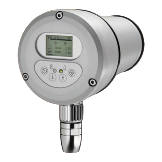
Product Description Product Description Structure of the F300K 1 Lens holder 2 F300K housing 3 Cover with operating unit UI (user interface) or LED display 4 Device connector 5 Connecting cable Fig. 3-1 The components of the F300K... -
Page 9: Basic Variants
Green LED: mode 1 Red LED: Flame OFF/stand-by – flashes in the event of a fault NOTICE For operation of F300K (with LED display) you need an external User Interface UI or the F300K Remote Software. F300K with user interface... -
Page 10: Functional Description
Microcontrollers 8 Ready The F300K analyses the flickering of the flame in the UV or IR range. For preparation for signal processing there is a semiconductor sensor (1) on a button strip. For each sensor signal, the level is adjusted by means of two adjustable amplifiers (2). These two amplifiers are lo- cated on the main board, as are the two microcontrollers (4). -
Page 11: User Interface
User Interface Operating and display elements You can adjust and operate the F300K compact flame scanner by using either the user inter- face (integrated in the F300K or as an external device) or the F300K Remote Software. You will find a description of the F300K Remote Software in a separate manual (publication no. -
Page 12: Menu Tree
User Interface Menu tree For access level 0 (parameterisation during commissioning not possible) Fig. 5-3 Menu tree 1 Menu password entry 2 Menu information 3 Menu device settings... -
Page 13: Operation
Operation Operation Main Menu This section gives you an overview of the displays and menus of the F300K. Initial images • Software version User Interface • Manufacturer Fig. 6-1 Initial image1 NOTICE If the operating unit appears in the initial screen, you can adjust the contrast of the display by means of the key combination ESC/UP or ESC/DOWN. -
Page 14: Enter Password
The following password levels are available: • Password level 1: Standard level - limited manual parameterisation possible. • Password level 2: Expert level - extensive manual parameterisation possible. • Password level 4: entry via the LAMTEC hotline only (factory level) - full manual parameterisation possible. -
Page 15: Reading Information
Operation Reading information The following sections describe how to get to the various information menus. Mode 1-3 monitoring parameters Device information Fault Fig. 6-6 Overview of the information menu 6.3.1 Read mode 1-3 Calling the information on the mode 1 Information on mode 1 2 Information on mode 2 3 Information on mode 3 Use the arrow keys to scroll up and down. - Page 16 Operation Icon Name Value Explanation AC signal 0 ... 2,500 mV Current effective value of amplified signal Switch-on 0 ... 2,500 mV Switching threshold for "flame ON" level Switch-off 0 ... 2,500 mV Switching threshold for "flame OFF" level Amplification 1 ...
-
Page 17: Reading The Device Setting
Use the arrow keys to scroll up and down. You will find more information on the values in the following table: Icon Name Value Explanation Device type Example: F300K UV-1 Serial number Consecutive number Current device temper- °C Temperature in flame sensor ature Operating hours 6 digits (e.g. -
Page 18: Displaying Faults
Operation 6.3.3 Displaying faults 6.3.3.1 Reading the cause of a problem Displaying the cause of a problem 1 Position in the fault list 2 Fault number 3 Fault time (operating hours, minutes) 4 Difference between the fault time and the current operating hours 5 Additional information on the fault NOTICE... -
Page 19: 6.3.3.2 Reading The Fault History
Changing the device settings The following sections explain the parameterisation of the device properties. Only LAMTEC qualified personnel are allowed to change the device settings. Parametrise User Interface Fig. 6-7 Overview of the "Device settings" menu... -
Page 20: Parameterising The User Interface
Operation 6.4.1 Parameterising the User Interface Setting the device parameters of the operating unit Apply with or reject with You will find more information on the values in the following table: Icon Name Value Explanation Display 1, background sec- Lighting duration, lighting onds 180 seconds = default... -
Page 21: Maintenance
The device is shipped as specified in the purchase order information. LAMTEC's terms and conditions of delivery and service and the general terms and conditions of delivery and service... -
Page 22: Repairs
Repairs Repairs When the F300K is replaced, it is necessary to replace it with a device with the same identifi- cation information. If possible, the parameterisation can be taken from the defective device, a backup file or the commissioning log. Any customisation of safety-related parameters that is necessary will be focused on the switching threshold. -
Page 23: Correcting Faults
NOTICE H and U processor The F300K reports errors of the H and U processors. The same error code contents are dis- played with the same number. They are differentiated by means of a preceding H or U. The operating hours when the error occurred and additional information are displayed in the error menu. -
Page 24: Error Codes At The Level Of The Operating Unit
Communication error Description Graphic C0001 Timeout At secure parameter transfer, the F300K did not respond within the safety time; in other words, the parameters were not accepted by the F300K. C0002 Communication The F300K is no longer responding. F300K is no longer reachable Bus improperly terminated, line lengthtoo long, interfer-... - Page 25 C0011 Multiple devices are connected. Two F300K Remote Software programmes have been detected on the bus. Remove one of the F300K Remote Software programmes from the bus or close it. C0012 Unknown device Data is received from a device with an unknown device ID.
-
Page 26: Information About The Repair Service
Correcting Faults Information About the Repair Service Please contact LAMTEC Service/Support if you have any questions. LAMTEC GmbH & Co.KG Sensors and Systems for Combustion Technology Wiesenstraße 6 D-69190 Walldorf Hotline: +49 (0) 6227 / 6052-33 email: support@lamtec.de... -
Page 27: Appendix
Appendix Appendix 10.1 Accessories NOTICE When installing electrical accessories you must ensure that the necessary protection class is reached. 10.1.1 FB30 External User Interface Fig. 10-1 External User Interface FB30... -
Page 28: F300K Remote Software
Appendix 10.1.2 F300K Remote Software Fig. 10-2 F300K Remote software... -
Page 29: Power Supplies
Appendix 10.1.3 Power Supplies Power pack FN20 Fig. 10-3 FN20 Top hat rail mounting Fig. 10-4 FN20-10 as a built-in unit Power pack FN30 Fig. 10-6 FN30-10 as a built-in unit Fig. 10-5 FN30-00 Top hat rail mounting 10.1.4 FG30 connection housing Fig. -
Page 30: Flame Scanner Testing Device
Appendix 10.1.5 Flame Scanner Testing Device Fig. 10-9 FFP30 flame-scanner testing device DANGER! Explosion hazard! Flame sensors must not be tested in a potentially explosive atmosphere. - Page 31 Appendix...
- Page 32 The information in this publication is subject to technical changes. LAMTEC Meß- und Regeltechnik für Feuerungen GmbH & Co. KG Wiesenstraße 6 D-69190 Walldorf Telefon: +49 (0) 6227 6052-0 info@lamtec.de Telefax: +49 (0) 6227 6052-57 www.lamtec.de Printed in Germany | Copyright 2018...
Need help?
Do you have a question about the F300K and is the answer not in the manual?
Questions and answers