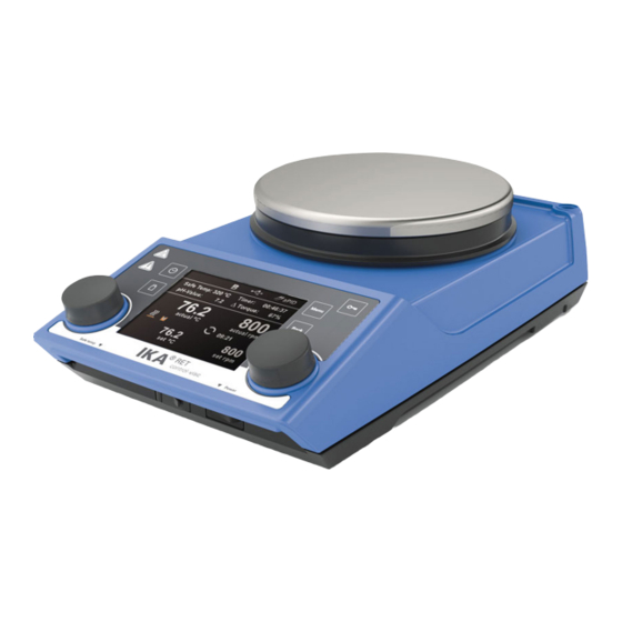
IKA RET control-visc Manual
Hide thumbs
Also See for RET control-visc:
- Operating instructions manual (88 pages) ,
- Operating instructions manual (136 pages)
Advertisement
Quick Links
Advertisement

Summary of Contents for IKA RET control-visc
- Page 1 20000004159 RET control-visc_042018 ® RET control-visc...
-
Page 2: Declaration Of Conformity
2011/65/EU and conforms to the standards or normative documents: EN 61010-1, EN 61010-2-010, EN 61010-2-051, EN 61326-1, EN 60529 and EN ISO 12100. A copy of the complete EU Declaration of Conformity can be requested at sales@ika.com. Warranty ®... -
Page 3: Safety Instructions
• Ensure the mounting plate remains clean. • Only process pathogenic materials in closed vessels under a suit- • Observe minimum distances between devices. Between device able extractor hood. Please contact IKA ® if you have any ques- and wall should be 100 mm (min), above the assembly should be tions. - Page 4 - Any damage should be notified immediately to the shipping - O Ring agent (post office, railway network or transport company) • Scope of delivery - RET control-visc heated magnetic stirrer O-Ring - Power supply cable - Operating instructions - Screwdriver (safety circuit)
- Page 5 Setting the safety temperature limit The maximum achievable heating plate temperature is restricted Setting the safety temperature limit After switching on the device, the safety temperature limit (7) can by an adjustable safety temperature limit. Once this limit has been reached, the device stops heating.
- Page 6 Operation Remove the protective film from the mounting plate before use! The “Back” menu key is used to change between menu items. Set the main switch (A) to the OFF position Insert the power supply cable into the mains socket (K) Start-up Set the main switch (A) to the ON position Standard mode A is selected (see “Menu (details)”)
- Page 7 Menu (overview) Menu structure Factory settings Stirring Torque trend measurement...………………………………………………… - Stirring bar decoupling…………………………………………………………….. - Intermittent Mode Run/Stop …………………………………..- Interval Run Time…..…………... 00:00 [mm:ss] Stop Time………………. 00:00 [mm:ss] Speed limit…………………………………………………...………..... 1700 rpm Heating Control method Fast PID (fPID)……………………………………... fPID Accurate PID (aPID)……………………………..
- Page 8 Time Out Set …………………..…………………………....00:30 [mm:ss] Safety Speed …………………………..…………………..... 100 rpm Temperature…………………..…………………....- Password ……..………………………………………………………………… 000 Safe temp confirmation ……..……………………………………..………… - Er5....……..…………………………………………………………..… - Languages English…………………………………………. English Settings Deutsch……………………………………..… - Français………………………………………… - Español………………………………………… - Italiano………………………………………… - 日本語………………………………………… - ………………………………………..- …………………………………..……… - Portuguese……………………………………...
- Page 9 Note: Intermittent mode The user is responsible for ensuring the suitability/function of the stirring bar decoupling monitoring for the current Intermittent mode consists of regular, cyclical interruption of conditions: stirring bar, speed, vessel, medium, etc. the stirring function. The run time and interval can both be set. Stirring bar decoupling monitoring does not work if the stirring When switching on the device, the time for each is displayed if bar already breaks away before the system has reached the...
- Page 10 Note: Temperature sensor By entering a value of 00:00:00 (hh:mm:ss), the counter is Calibration: activated. The counter shows the time elapsed during the current In order to use tolerances to limit temperature deviations, the experiment. user can calibrate the temperature sensor in conjunction with the device.
- Page 11 Mode C Safety In this mode, the device can be used either with or without a temperature sensor. Time out When the device is switched on using the main switch, the stirring and heating functions are started in the last set status and at the The “Time out”...
- Page 12 Information: The ”Information” option offers the user an overview of the most Communication: important system settings of the stirrer RET control-visc. Bluetooth The ”Bluetooth” option allows the user to activate/deactivate the ”Bluetooth” function. A tick shows that the option is activated.
- Page 13 Command syntax Installation The following points should be noted for the instruction set: • Commands are generally sent from the computer (master) to First, download the latest driver for IKA ® devices with USB in- the lab device (slave). terface from http://www.ika.com/ika/lws/download/usb-driver.
- Page 14 If, once this function has been activated (see NAMUR commands), there is no retransmission of the command from the computer ® The following adapters and adapter cables are available from IKA within the set time (“watchdog time”), the heating and stirring for connecting the RET control-visc to external devices.
-
Page 15: Troubleshooting
Troubleshooting The safety circuit test takes place within 20 seconds of switching The device will indicate that there is a fault by displaying an error message “Er X” (see table) on the screen. on the device; after the test, the other monitoring functions are activated. -
Page 16: Maintenance And Cleaning
- device manufacturing number; see rating plate Remove the device from the mains - software version (second value displayed when switching on the before cleaning. device) - position number and description of spare part; see www.ika. Only use cleaning materials recommended by IKA ® com. Repairs... - Page 17 Number of stirring positions Max. motor power consumption Max. motor output Speed range 0; 50 to 1700 Target speed setting resolution Actual speed display resolution Speed variation (without load, 115/230 V, at 1700 rpm, RT 25 °C) Stirring capacity (H Heating Self-heating of the hotplate (RT:22 °C/duration:1 h) °C...


Need help?
Do you have a question about the RET control-visc and is the answer not in the manual?
Questions and answers