
Related Manuals for MIOX RIO Series


Summary of Contents for MIOX RIO Series
- Page 1 RIO SERIES ON-SITE GENERATOR M1-M5 H1-H5 Installation, Operation, and Maintenance Manual March 26, 2019...
- Page 2 MIOX maintains a constant product improvement program that may affect design and/or specifications. The company reserves the right to make these changes without prior notice or liability. Portions of the MIOX OSGs are covered by U.S. patent. Customer Service 5601 Balloon Fiesta Parkway NE, Suite A...
-
Page 3: Table Of Contents
Components of the System ................... 8 Space Requirements ....................8 Security ........................ 10 RIO Series OSG System and Ancillary Components ............10 RIO Series OSG System Optional Equipment ............... 11 Installation ........................12 Recommended Tools for Installation: RIO Series OSG ............. 13 ... - Page 4 MIOX RIO Series Operators Manual Brine Silos ......................31 Brine Pressure Boost System Installation (Optional) ............32 Oxidant Storage Tank Installation ................32 Ventilation Requirements ..................32 Level Switch Installation ..................36 Pressure Transducer Installation (Optional) ..............37 ...
- Page 5 MIOX RIO Series Operators Manual Weekly Maintenance ....................57 Monthly Maintenance....................58 Quarterly Maintenance ....................58 Annual Maintenance ....................58 Electrolytic Cell Replacement ..................59 Storage of Equipment ....................60 Troubleshooting Guide ....................61 ...
- Page 6 MIOX RIO Series Operators Manual List of Figures Figure 1 RIO Series On-Site Generator ................8 Figure 2 RIO Series OSG Space Requirements ..............9 Figure 3 RIO Series OSG Compartments ................15 Figure 4 Rear View of RIO OSG Showing Main Power Conduit ..........16 ...
- Page 7 MIOX RIO Series Operators Manual List of Tables Table 1 Tank Level Connector Name and Description............19 Table 2 Tank Level Status ....................19 Table 3 Auxiliary Relay Connector Name and Description ............ 20 Table 4 Auxiliary 24V Power Connector Name and Description ..........21 ...
-
Page 8: Introduction
For details of specific NSF standards for specific MIOX equipment, please consult with MIOX. NSF listings are also available through NSF International at (800) NSF-Mark or their web site at www.nsf.org. -
Page 9: Components Of The System
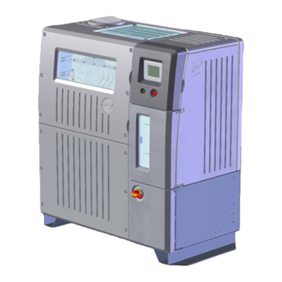
MIOX RIO Series Operators Manual Components of the System The RIO Series OSG (Figure 1) must be installed by trained technicians. After installation and system startup, the units operate automatically and self-diagnose. Figure 1 RIO Series On-Site Generator Space Requirements Appropriate floor-space must be identified to accommodate the OSG enclosure and sufficient working space clearance (Figure 1-2). -
Page 10: Figure 2 Rio Series Osg Space Requirements
MIOX RIO Series Operators Manual Figure 2 RIO Series OSG Space Requirements P/N: 102-00076-G Page 9... -
Page 11: Security
Electrolytic Cell The proprietary membrane-less electrolytic cell produces a mixture of oxidants and is manufactured by MIOX. The RIO Series cell is configured to provide modular cell capacity depending on the disinfectant requirement. Each MIOX cell module is configured to provide 60 lb/day Free Available Chlorine (FAC), while each HYPO cell module is rated to provide 100 lb/day FAC. -
Page 12: Rio Series Osg System Optional Equipment
MIOX RIO Series Operators Manual Tubing and Fittings All tubing and fittings shipped by MIOX meet Schedule 80 specifications. The U.S. specifications ensure that materials are rated for proper thickness, pressure requirements, and temperature resistance for the specific application. RIO Series OSG System Optional Equipment Heater or Chiller If the OSG feed water temperature is less than 40°F (5°C) or greater than 95°F (35°C),... -
Page 13: Installation
Do not defeat or tamper with electrical interlocks or lockout mechanisms. All MIOX units require a good earth ground. A neutral is not a substitute for a proper earth ground. Electrical wiring to all MIOX units should be performed by a certified electrician. -
Page 14: Recommended Tools For Installation: Rio Series Osg
Glue - use correct type for pipe material • Primer/cleaner - use correct type for pipe material • Teflon Tape • Strap wrench • 12” pipe wrench Untrained Persons should not attempt to install of operate MIOX equipment. P/N: 102-00076-G Page 13... -
Page 15: Receiving And Unpacking The Rio Series Osg
Service. Securing the Cabinet The RIO Series OSG is designed with mounting feet and holes for securing the enclosure to the floor. While there are no vibrational components that would cause the system to move, good seismic design practice and building codes in some areas require that the unit be secured to the floor. -
Page 16: System Description
MIOX RIO Series Operators Manual System Description The RIO Series OSG is made up of six compartments, Controls, Switch Gear, Power Supply, Cooling, Plumbing, and Cell (Figure 3). Cell Controls Plumbing Power Supply Cooling Switch Gear Figure 3 RIO Series OSG Compartments... -
Page 17: Electric Connections Required For Start-Up
MIOX RIO Series Operators Manual Electric Connections Required for Start-Up Normal precautions should be taken with regard to electrical components in the vicinity of a water source. Electrical Power Connection The power cable to the OSG is run through the cooling compartment into the switch gear compartment. -
Page 18: Figure 5 Incoming Power
MIOX RIO Series Operators Manual System Power Ratings Power In 4x Screws Figure 5 Incoming Power Figure 6 Switch Gear Cover Figure 7 Power Routing to Switch Gear P/N: 102-00076-G Page 17... -
Page 19: Control System/Rear Panel Connections
MIOX RIO Series Operators Manual Control System/Rear Panel Connections The RIO Series OSG features an Allen Bradley Micrologix 1400 PLC to maintain consistent cell control. The operator interface is an Allen Bradley Panelview Plus 600 Touch screen display. Connection to site SCADA systems is done directly from OSG controls using the RJ45 cable. -
Page 20: Tank Level Inputs
MIOX RIO Series Operators Manual Tank Level Inputs The tank level connector provides field connection points for external floats, the dry contact outputs on a tank level controller, or the dry contact outputs of a plant PLC or other control device. -
Page 21: Auxiliary Relay Connection
MIOX RIO Series Operators Manual Auxiliary Relay Connection The auxiliary relay connector provides field connection points for three auxiliary relays, alarm, brine boost, and water boost. Each relay has two sets of normally open contacts. The contacts are rated for 277 VAC at 30 Amps or 28VDC at 20 Amps. Table 3 provides the description for each connection. -
Page 22: Auxiliary 24V Power Connection
MIOX RIO Series Operators Manual Auxiliary 24V Power Connection The auxiliary power connector provides field connection points to provide 24V power to the auxiliary relays. Current is limited to 1 AMP and is fused internally. Table 4 provides the description for each terminal... -
Page 23: Dilution Air Connection
The connections supported include a MIOX external dilution air enable, MIOX external dilution air system failure input, and two other failure inputs. The failure inputs can be connected to either external differential pressure switches or an external flow switch with dry contacts. -
Page 24: Hydrogen/Hardness Connections
MIOX RIO Series Operators Manual Hydrogen/Hardness Connections The Hydrogen/Hardness connector provides field connection points for an external hydrogen monitor and/or an external hardness monitor. The hydrogen monitor inputs require both normally closed and normally open dry contacts. The hardness monitor input only requires normally closed dry contacts. -
Page 25: Ethernet Connection
MIOX RIO Series Operators Manual Ethernet Connection The Ethernet connector provides connection to site SCADA systems. Table 7 provides the pin-out for the connector. Table 7 Ethernet Connector Pin-Out Pin Name not used not used not used not used P/N: 102-00076-G... -
Page 26: Plumbing Connections Required For Startup
OSG. Feed Water Connection Feed water requirements for the RIO Series OSG are given in Table 8. Additional feed water is based on water softener requirements. Consult water softener specifications for required flow rates. A minimum of 35 psi (242 kPa) feed water pressure at the OSG is required to ensure stable flow and a continuous supply of 5-25 psi (34-172 kPa) brine feed to the electrolytic cell. -
Page 27: Brine Feed Connection
OSG, flush water through the softener until the water is clean and clear. Brine Feed Connection The brine feed connection to the RIO Series OSG is ½” schedule 80 PVC. The OSG is equipped with a ½” PVC male union. A Y-strainer assembly with a ½” PVC female union is provided to attach to the brine inlet. -
Page 28: Oxidant Discharge
Figure 15 Feed Water, Brine, Y-strainer, and Oxidant Union Connections Oxidant Discharge The oxidant discharge connection from the RIO Series OSG is 1¼” schedule 80 CPVC but increases in size to 1½”. The OSG is equipped with 1½” CPVC male union half. Proper connection is accomplished with a 1½”... -
Page 29: Drains
MIOX RIO Series Operators Manual Do not use any valves in the mixed-oxidant or sodium hypochlorite lines other than the three-way valve provided by MIOX. These valves have an open center configuration that prevents the blockage of flows from the cell. Failure to use MIOX supplied three-way valves may void the warranty. -
Page 30: Brine Generator Installation (Optional)
Note: Use Teflon tape on threaded plumbing connections. Brine Tank Float and Spray Ring Assembly MIOX has adapted an off-the-shelf float valve and spray ring assembly for providing saturated brine to the on-site generator. Kinetico® provides KCBS (Kinetico® Central Brine System) which includes a float valve assembly with a 28”... -
Page 31: Figure 17 Internal View Float Valve Assembly And Detail
MIOX RIO Series Operators Manual The spray ring assembly provides a more consistent means of mixing the salt and water to meet the brine saturation requirement. The spray ring at the top of the tank eliminates possibility of channeling (or short circuiting) the water through the outlet of the tank. Adding a quartz rock bed at the bottom the tank also reduces the possibility of brine channeling for any application. -
Page 32: Brine Silos
MIOX RIO Series Operators Manual Quartz Rock In order to accommodate various salt types, MIOX provides a cross-shaped, slotted pipe manifold. Thread the manifold into the bottom tank adapter. Place 7 inches of ½” x ¼” NSF quartz rock in the bottom of the tank. Rake it flat and cover the slotted pipe manifold. Place 5 inches of ¼”... -
Page 33: Brine Pressure Boost System Installation (Optional)
0.5 in. per foot (1.3 cm per meter), sloping downward from the main vent towards the tank. If the oxidant tank is not supplied by MIOX, a drop tube assembly and LBS vent assembly must be fabricated on-site. -
Page 34: Figure 19 Oxidant Tank Vents
Tank Vent to operate safely. An optional Dilution Air System can be supplied upon request and on large installations, a combination stand Hydrogen pipe and Dilution Air System can be used. Refer to MIOX ’s Safety White Paper for additional details. -
Page 35: Figure 20 Oxidant Storage Tank With Safety Placards
Safety placards are required on oxidant tanks and are attached to all oxidant tanks shipped directly from MIOX. Oxidant tanks shipped directly from the tank manufacturer must have the MIOX supplied safety placards attached to the outside wall of the oxidant tank (Figure 20). -
Page 36: Figure 21 Ventilation Requirements
MIOX oxidant tanks require that they be vented to the atmosphere outside the facility. Proper configuration of vent assemblies (Figure 21) is vital to ensure safety. Figure 21 Ventilation Requirements... -
Page 37: Level Switch Installation
RIO Series OSG, the switch is shipped separately. The switch is designed to operate with the RIO Series OSG. To install the level switch in the tank, complete the following steps (Figure 22): 1. -
Page 38: Pressure Transducer Installation (Optional)
MIOX RIO Series Operators Manual system uses electronic commands to start and stop. There are three different commands you can send to the system. The first command is used to tell the system to run or stop. The other two are used together to makes sure the connection between the OSG and network controller is functioning. -
Page 39: Oxidant Tank Lid
The injection system should be designed by a qualified engineer, MIOX distributor, or salesperson. Refer to Injection System Manufacturer’s Manual for Installation Guidelines Overflow Port An overflow port connection fitting is provided at the top of the oxidant tank. -
Page 40: Cell Installation And Removal
MIOX RIO Series Operators Manual Cell Installation and Removal All RIO systems are shipped with the Cell pre-installed. Instances when the cell must be removed or installed, the procedure below should be followed: Removal Ensure the OSG is in STOP mode and isolate 400-480 VAC power from the unit. Remove the cell lead guards by unscrewing the fasteners at the cell cover. -
Page 41: Electrical Connections
MIOX RIO Series Operators Manual Electrical Connections Connection of the cell electrical leads to the cell is accomplished by matching the red leads to the anode or positive buss bars and the black leads to the cathode or negative buss bars. -
Page 42: Figure 25 Cell Lead And Buss Bar Connection
MIOX RIO Series Operators Manual Cell Lead/Bussbar Connection Apply electric joint compound to the cell lead lug and the ½” bolt. Align the cell lead lug with the hole on the buss bar and fasten with the ½” bolt, washers, and nut. The bolt head should face the front of the cell followed by a split washer, flat washer, cell lead, bussbar, flat washer, and nut (Figure 25). -
Page 43: Plumbing Connections
MIOX RIO Series Operators Manual Plumbing Connections Plumbing connections to the cell depend on the number of cell modules that make up the cell assembly. For a single module cell (M1 or H1), the plumbing inlet and outlet fittings are installed directly to the cell (Figure 26). -
Page 44: Figure 27 Multiple Module Cell Inlet/Outlet Manifold
MIOX RIO Series Operators Manual Figure 27 Multiple Module Cell Inlet/Outlet Manifold a) Inlet Plumbing from Rear b) Outlet Plumbing from Rear c) Outlet Plumbing Assembly P/N: 102-00076-G Page 43... -
Page 45: Cell Guard Installation
MIOX RIO Series Operators Manual Cell Guard Installation Cell guards provide protection from the cell leads. Cell guards are shipped pre-assembled, a left side (Figure 28) and a right side. To install, disassemble the front piece of the guard from the middle piece. Position the middle and back pieces of the guard on the cell, sliding the slots on the guard onto the socket head shoulder screws on the cell (Figure 29). -
Page 46: Figure 29 Location Of Socket Head Shoulder Screws - Back
MIOX RIO Series Operators Manual Figure 29 Location of Socket Head Shoulder Screws – Back Figure 30 Location of Socket Head Shoulder Screws - Front P/N: 102-00076-G Page 45... -
Page 47: Operations
The oxidant solution is a disinfectant - NOT DRINKING WATER – and therefore should NOT be consumed without diluting it with water. The RIO Series OSG is not a desalinization device for making fresh water from salt water, but instead uses salt water in making oxidant solution. -
Page 48: Checks Prior To Startup
MIOX RIO Series Operators Manual Checks Prior to Startup Prior to initial OSG start-up, the following items should be checked: 1. Hose fittings tightened 2. Electrical connections to cell electrodes good [40 ft./lbs. (54 Nꞏm)] 3. Electrical power connection good (correct wiring at disconnect switch) ... -
Page 49: Routine Operations
MIOX RIO Series Operators Manual Routine Operations Turn On Disconnect Switch The disconnect switch is located on the outside of the switch gear compartment (Figure 31). Once the disconnect switch is moved to the ON position, the display and OSG will power up. -
Page 50: Startup Sequence/Operating Window
Figure 32 Main Display Screen Startup Sequence/Operating Window The RIO Series OSG goes through a start-up sequence that includes brine proportion pump activation and purging the cell of warm water. When power is applied to the cell, the current flowing through the cell is measured. During normal operation, the amperage will fluctuate slightly. -
Page 51: Brine Boost Pump Commissioning
MIOX RIO Series Operators Manual During the startup from standby mode, the OSG also goes through a startup sequence. When the low level switch in the oxidant storage tank is activated, the solenoid opens to allow water flow for 60 seconds. Cell power is applied, the brine proportion pump comes on, and the OSG should come into the operating window within five minutes. - Page 52 MIOX RIO Series Operators Manual In Run mode, the brine flow is adjusted to achieve and maintain a constant electrical Current Point (CSP) to the cell. Self-Cleaning Mode For Mixed Oxidant Solution (MOS) configurations M1-M5, the requirements to enter into a self- cleaning mode are based upon number of hours of operations since initial startup or last cleaning.
-
Page 53: System Status Lights
MIOX RIO Series Operators Manual Quick Shutdown - is used when the OSG needs to shut down without a purge delay. Quick shutdown occurs with Low Water Pressure (run mode), Very High Current, Rupture Disk Failure, or Hydrogen Monitor Alarm. -
Page 54: Fault Conditions
MIOX RIO Series Operators Manual Fault Conditions Anything that stops the system is considered a fault. There are two types of faults: soft and hard. With a soft fault, the system will automatically restart when the conditions that caused it go away. A hard fault requires user intervention to reset the system. - Page 55 MIOX RIO Series Operators Manual Fault Name Condition Time Cell Water Auto Delay Power Retry (sec) Removed No air flow signal while fan run command on. No Air Flow Fault Liquid detected on rupture disk probe. Rupture Disk Fail No contact status signal when contact enable signal on.
-
Page 56: Water Flow Control Valve Reset Procedure
MIOX customer support provider. System Shutdown procedure This sequence for shutdown of the RIO Series OSG is designed to properly flush the electrolytic cell and help maintain the overall condition of the MIOX equipment. When turning the system off for a prolonged period of time, it is important to follow this sequence: 1. -
Page 57: General Periodic Maintenance
MIOX RIO Series Operators Manual General Periodic Maintenance The RIO Series OSG should be monitored periodically to ensure that the unit is running properly. MIOX recommends daily, weekly, monthly, and quarterly checks. In order to maintain a history of system performance and assist in troubleshooting and warranty work, it is recommended that a log be kept near the OSG for easy record keeping. -
Page 58: Weekly Maintenance
Check Feed Water Pressure (35 to 100 psi; 241.5 to 689 kPa) – The feed water pressure of some water systems tends to fluctuate. If water pressure goes below 35 psi (241.5 kPa) or above 100 psi (689 kPa), it could damage the MIOX OSG. -
Page 59: Monthly Maintenance
MIOX RIO Series Operators Manual Monthly Maintenance Check Power – Verify that AC supply voltage is within 480 VAC +/-10% for standard units. For 400V units, verify it is within 400 +/- 10%. Toggle Day Tank Float Switch – The system is in standby when both floats are up. -
Page 60: Electrolytic Cell Replacement
You may return a defective product to your original point of purchase, or the authorized MIOX dealer or distributor from whom you purchased the product. Please confirm the terms of its return policies prior to returning the product. Typically, you... -
Page 61: Storage Of Equipment
MIOX RIO Series Operators Manual Storage of Equipment If the system will be off for a prolonged time period, water feed to the MIOX OSG should be turned off at the inlet to the water softener. In addition, the brine tank, tubes, and piping should be drained, and the brine proportion pump should be flushed with clean water. -
Page 62: Troubleshooting Guide
MIOX RIO Series Operators Manual Troubleshooting Guide Table 14 Troubleshooting Guide System Display Fault Cause Remedial Action (most likely to least) Very High Oxidant Cell outlet 1. Low flow 1. Verify the through cell water flow is Temp temperature exceeds 2. - Page 63 MIOX RIO Series Operators Manual System Display Fault Cause Remedial Action (most likely to least) No Air Flow Air flow switch is not 1. Inadequate air 1. Verify the slow flow switch is satisfied 2. Fan motor physically failure moving when 3.
- Page 64 MIOX RIO Series Operators Manual System Display Fault Cause Remedial Action (most likely to least) Very High Cell Current Cell Amperage 1. Low water flow 1. Check fuse for 2. Water flow water solenoid exceeds max limit for control valve 2.
- Page 65 MIOX RIO Series Operators Manual System Display Fault Cause Remedial Action (most likely to least) Low H O Temp Feed water 1. Feed water 1. Check feed temperature water temperature <40° F too low temperature. 2. Cell inlet Contact MIOX...
-
Page 66: Figure 33 Switch Gear Panel Components
MIOX RIO Series Operators Manual Figure 33 Switch Gear Panel Components Table 15 Switch Gear Panel Components Label Component Label Component Label Component Breaker Power Monitor TPM 1,2,3 Transient Surge Module Switch Disconnect Power Supply Fuse Contactor Safety Relay... -
Page 67: Figure 34 Interface Board
MIOX RIO Series Operators Manual Figure 34 Interface Board P/N: 102-00076-G Page 66... -
Page 68: Procedures
MIOX RIO Series Operators Manual Procedures Brine Pump Replacement The brine pump has been specifically designed for this application. All metal parts in contact with brine are made of Hastelloy, which is a nickel-based alloy impervious to brine. The pump is magnetically coupled to the motor. To avoid brine leakage into the magnetic coupling housing, all seams are sealed. -
Page 69: Installing The New Brine Pump
19. Remove the damaged disk and replace with a new one. Replacement disks have been furnished with the OSG operations kit. If more are needed contact MIOX customer service or other appropriate service representative. 20. Carefully thread the union back together with the disk centered inside. -
Page 70: Rupture Probe Maintenance
4. Reinsert probe into the push-in connector. Figure 36 Rupture Probe Acid Washing the Cell See MIOX Acid Washing Cell Procedure (P/N: 102-00009). Contact MIOX Customer Service if copy is not included with the Acid Wash Kit. P/N: 102-00076-G Page 69... -
Page 71: Oxidant Demand Testing
1. Determine the amount of oxidant and sample water to be used. Always start with start with a 5 ppm dose for the first test. Suppose you are using a MIOX OSG that just generated an oxidant solution concentration of 250 ppm. First, you must determine the... - Page 72 100 mL since it provides enough volume for multiple FAC measurements at the various testing times. Example: Determine the oxidant and sample water volumes for the 1, 3, and 5 ppm doses. Given that MIOX OSG is still generating an oxidant concentration of 250 ppm. 1 ppm 3ppm 5ppm...
- Page 73 MIOX RIO Series Operators Manual Procedure Stagger preparation of each dilution by several minutes to allow enough time for accurate analysis of FAC at each dilution. FAC readings should be taken at the following times: T = 0, 30 minutes, 60 minutes, and 90 minutes. Readings beyond 90 minutes are determined by interpretation of data from the first 90 minutes.
- Page 74 MIOX RIO Series Operators Manual Oxidant Demand Determination After 90 minutes, determine which sample has the FAC residual nearest to the desired residual specified by the water system operator. If a desired residual is unknown, look for a FAC slightly greater than 0.2 ppm, which is usually the standard required by the state.
-
Page 75: Chlorine Production Testing
Equipment Needed • 250 mL glass beaker • 3000 mL, or 5000 mL glass jar with lid (depending on MIOX OSG being tested) • Pipette that can accurately measure 0.5 mL or 1 mL samples • Chlorine Test Kit (i.e. DPD, Color Wheel, Colorimeter or AccuVac) •... - Page 76 5000 mL line with demand-free water, depending on which dilution technique you are using: • MIOX Series Systems: Use a 1:2500 ratio (= 1.0 mL solution to 2500 mL water or 2 mL solution to 5000 mL water.) • HYPO Series Systems: Use a 1:5000 ratio (= 1 mL solution to 5000 mL water)
- Page 77 MIOX RIO Series Operators Manual 3. Rinse the pipette several times by drawing in several mL of oxidant and discarding it. 4. With the pipette, accurately measure the solution sample needed (according to the dilution technique used above) and add to the jar containing demand-free water.
- Page 78 MIOX RIO Series Operators Manual Measuring Flow Total production of a system is the product of the concentration of the solution (determined above) and the volumetric flow of the solution over a period of time. Low concentrations of oxidant are often erroneously associated with low production. In order to calculate the total production for the system, the flow rate must also be determined and adjusted if necessary.
-
Page 79: Appendices
MIOX RIO Series Operators Manual APPENDICES A. Water Quality Guidelines B. Salt Quality Guidelines P/N: 102-00076-G Page 78... -
Page 80: Appendix A - Water Quality Guidelines
These factors can affect the oxidant demand of each individual water system, the oxidant production of the MIOX system, or the life of the cell itself. It is important to use “worst case” measures since water quality can vary from season to season. - Page 81 MIOX RIO Series Operators Manual † Iron may deposit Fe(OH)3 on the anode, causing an electrical “blind”, which would increase the brine proportion pump signal voltage (brine proportion pump speed) needed for the system to reach the operating window. Chlorine production would remain the same, but salt conversion efficiency will decrease.
-
Page 82: Appendix B - Salt Quality Guidelines
MIOX RIO Series Operators Manual Appendix B – Salt Quality Guidelines MIOX requires that all Self Cleaning RIO Systems use a granular salt that meets or exceeds the purity percentages listed below. For additional information consult the MIOX Salt Guidelines white paper (P/N: 106-00008).
Need help?
Do you have a question about the RIO Series and is the answer not in the manual?
Questions and answers