Sign In
Upload
Manuals
Brands
MIOX Manuals
Portable Generator
RIO M1
MIOX RIO M1 Manuals
Manuals and User Guides for MIOX RIO M1. We have
1
MIOX RIO M1 manual available for free PDF download: Installation, Operation And Maintenance Manual
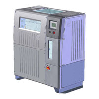
MIOX RIO M1 Installation, Operation And Maintenance Manual (82 pages)
ON-SITE GENERATOR
Brand:
MIOX
| Category:
Portable Generator
| Size: 4 MB
Table of Contents
Table of Contents
3
Introduction
8
Regulatory Compliance
8
Environmental Protection Agency (US EPA)
8
NSF International
8
State Approvals
8
List of Certifications
8
Components of the System
9
Space Requirements
9
Figure 1 RIO Series On-Site Generator
9
Figure 2 RIO Series OSG Space Requirements
10
Security
11
RIO Series OSG System and Ancillary Components
11
RIO Series OSG System Optional Equipment
12
Installation
13
Recommended Tools for Installation: RIO Series OSG
14
Mechanical Tools
14
Plumbing Tools
14
Receiving and Unpacking the RIO Series OSG
15
Securing the Cabinet
15
System Description
16
Figure 3 RIO Series OSG Compartments
16
Electric Connections Required for Start-Up
17
Electrical Power Connection
17
Figure 4 Rear View of RIO OSG Showing Main Power Conduit
17
Figure 5 Incoming Power
18
Figure 6 Switch Gear Cover
18
Figure 7 Power Routing to Switch Gear
18
Control System/Rear Panel Connections
19
Figure 8 Rear Panel Connections
19
Tank Level Inputs
20
Figure 9 Tank Level Connector
20
Table 1 Tank Level Connector Name and Description
20
Table 2 Tank Level Status
20
Auxiliary Relay Connection
21
Figure 10 Auxiliary Relay Connector
21
Table 3 Auxiliary Relay Connector Name and Description
21
Auxiliary 24V Power Connection
22
Figure 11 Auxiliary 24V Power Connector
22
Table 4 Auxiliary 24V Power Connector Name and Description
22
Dilution Air Connection
23
Figure 12 Dilution Air Connector
23
Table 5 Dilution Air Connector Name and Description
23
Hydrogen/Hardness Connections
24
Figure 13 H 2 /Hardness Connector
24
Table 6 Hydrogen/Hardness Connector Name and Description
24
Ethernet Connection
25
Table 7 Ethernet Connector Pin-Out
25
Plumbing Connections Required for Startup
26
Feed Water Connection
26
Table 8 Feed Water Requirements
26
Brine Feed Connection
27
Figure 14 Plumbing Enclosure
27
Oxidant Discharge
28
Figure 15 Feed Water, Brine, Y-Strainer, and Oxidant Union Connections
28
Drains
29
Brine Generator Installation (Optional)
30
Figure 16 Float Valve Assembly and Detail
30
Figure 17 Internal View Float Valve Assembly and Detail
31
Brine Silos
32
Brine Pressure Boost System Installation (Optional)
33
Oxidant Storage Tank Installation
33
Ventilation Requirements
33
Figure 18 Brine Pressure Boost System
33
Figure 19 Oxidant Tank Vents
34
Figure 20 Oxidant Storage Tank with Safety Placards
35
Figure 21 Ventilation Requirements
36
Level Switch Installation
37
Figure 22 Level Switch Installation
37
Pressure Transducer Installation (Optional)
38
Figure 23 Pressure Transducer Assembly
38
Oxidant Tank Lid
39
Feed Line Connection/Injection System
39
Overflow Port
39
Cell Installation and Removal
40
Removal
40
Installation
40
Electrical Connections
41
Figure 24 Cell Lead Connections
41
Table 9 Electrical Connections Per Cell Module
41
Figure 25 Cell Lead and Buss Bar Connection
42
Plumbing Connections
43
Figure 26 Cell Plumbing Connectons - 1 Module
43
Figure 27 Multiple Module Cell Inlet/Outlet Manifold
44
Cell Guard Installation
45
Figure 28 Cell Guard Pre-Assembly
45
Figure 29 Location of Socket Head Shoulder Screws - Back
46
Figure 30 Location of Socket Head Shoulder Screws - Front
46
Operations
47
Initial Settings and Startup Checks
47
Electrical Check
47
Initial Salt Filling
47
Checks Prior to Startup
48
Brine Boost Operation
48
Water Softener Operation
48
Routine Operations
49
Turn on Disconnect Switch
49
Push Run/Stop Switch
49
Figure 31 Display Screen, Run/Stop Switch, and Disconnect Switch
49
Startup Sequence/Operating Window
50
Figure 32 Main Display Screen
50
Brine Boost Pump Commissioning
51
Operation Controls
51
Modes of Operation
51
System Status Lights
53
Table 10 LED Status Lights
53
Table 11 Output Testing
53
Fault Conditions
54
Table 12 Fault Conditions
54
Water Flow Control Valve Reset Procedure
56
System Shutdown Procedure
56
General Periodic Maintenance
57
Daily Maintenance
57
Weekly Maintenance
58
Table 13 Perimeter Bolt Torque Specifications
58
Monthly Maintenance
59
Quarterly Maintenance
59
Annual Maintenance
59
Electrolytic Cell Replacement
60
Storage of Equipment
61
Troubleshooting Guide
62
Table 14 Switch Gear Panel Components
66
Figure 33 Switch Gear Panel Components
66
Figure 34 Interface Board
67
Procedures
68
Brine Pump Replacement
68
Removing the Old Brine Pump
68
Installing the New Brine Pump
69
Rupture Disk Maintenance
69
Replacing the Rupture Disk Diaphragm
69
Rupture Probe Maintenance
70
Acid Washing the Cell
70
Figure 35 Rupture Disk Ruptured Diaphragm
70
Figure 36 Rupture Probe
70
Oxidant Demand Testing
71
Chlorine Production Testing
75
Appendices
79
Appendix A - Water Quality Guidelines
80
Appendix B - Salt Quality Guidelines
82
Advertisement
Advertisement
Related Products
MIOX RIO M3
MIOX RIO M2
MIOX RIO M4
MIOX RIO M5
MIOX RIO ZUNI
MIOX RIO Series
MIOX RIO H3
MIOX RIO H4
MIOX RIO Zuni Series
MIOX RIO H5
MIOX Categories
Portable Generator
Inverter
More MIOX Manuals
Login
Sign In
OR
Sign in with Facebook
Sign in with Google
Upload manual
Upload from disk
Upload from URL