Advertisement
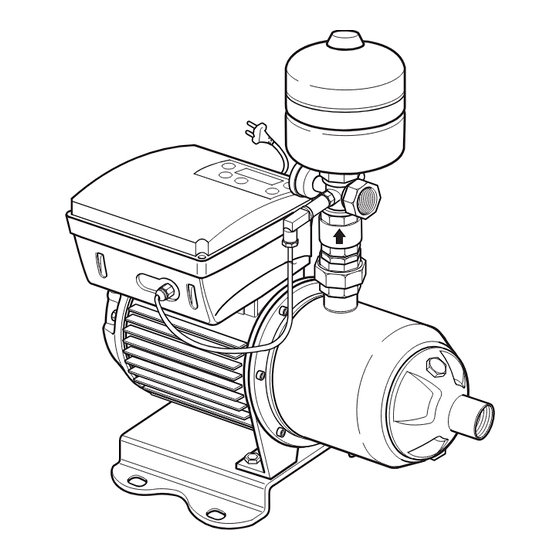
INVERTER PUMP
Installation, Operation, and Maintenance Manual
♣ Before installing and operating the pump, the Safety Instructions must be
thoroughly read for the proper use of the pump.
♣ Before installation, this manual should be completely studied. / Read this
manual completely before any work on your unit.
♣ Keep this manual handy for future reference.
♣ Product warranty is attached to this manual.
♣ ATTENTION: To keep the pump at top efficiency, this manual
should be thoroughly studied.
Models
PBI-L203MA
PBI-L205MA
PBI-L404MA
PBI-L405MA
PBI-L802MA
PBI-L803MA
Advertisement
Table of Contents

Related Manuals for Wilo PBI-L203MA


Summary of Contents for Wilo PBI-L203MA
- Page 1 INVERTER PUMP Installation, Operation, and Maintenance Manual Models PBI-L203MA PBI-L205MA PBI-L404MA PBI-L405MA PBI-L802MA PBI-L803MA ♣ Before installing and operating the pump, the Safety Instructions must be thoroughly read for the proper use of the pump. ♣ Before installation, this manual should be completely studied. / Read this manual completely before any work on your unit.
- Page 2 ▶ Improper operation not outlined in this manual may cause defects or physical damage that users are liable for. ▶ The WILO Pumps Customer Service Department is available for customers to ask any questions and to give an advice on errors on this manual. Call our dealers or headquarter.
- Page 3 APPLICATION OF THE PUMP ▶ The pump is suitable for boosting low water pressure in apartment houses, apartments, weekend cottages, inns, houses, small sprinklers, school buildings, dormitories, and other buildings, providingconstant water pressure. SPECIFICATIONS OF THE PUMP ▶ The embedded converter for constant pressure enables control of the operating pressure depending on the height of a building.
-
Page 4: Table Of Contents
CONTENTS Thank you for purchasing our pump. Follow the recommended instructions in this manual. Changing Operating Mode ....18 Thank you for Reversing the Rotation of the Pump ..19 purchasing our pump ......2 Keypad and Display ......19 Features ........... -
Page 5: Safety Instructions
SAFETY INSTRUCTIONS These instructions contain important information which must be followed when installing and operating the pump. These operating instructions must therefore be read before assembly and commissioning by the installer and the responsible operator. Both the general safety instructions in the "Safety precautions" section and those in subsequent sections indicated with danger symbols should be carefully observed. -
Page 6: Transportation And Installation Instructions
TRANSPORTATION AND INSTALLATION WARNING! ● Before installation, repair or removal ● Install a breaker of electric leakage of the pump, the power supply must be of under 30mA of rated sensitivity disconnected. to prevent electric shock. Breaker Breaker ● ● Pay special attention to extensions of the power cord. - Page 7 TRANSPORTAION AND INSTALLATION CAUTION! ● Minimize the number of elbows to prevent water leakages in the piping and to decrease water resistance. Gas Pipe ● Connect the earth wire before operation to prevent electric shock when the electric insulation is faulty. Earth wire ●...
- Page 8 INSTALLATION 운반·설치상의 주의사항 Installation process - The pump should be installed indoors. In case of installing outdoors, set eaves to avoid exposure to wind and rain, and prevent the pump from freezing. - The pump should be in pressurized condition. (Recommended suction pressure: 0.2kgf/cm To prevent dry running, the water tank should always be higher than the suction port of ATTENTION! the pump.
- Page 9 INSTALLATION 운반·설치상의 주의사항 Wiring Only a qualified electrician should connect cables. Install a circuit breaker and connect ATTENTION! earth wire to prevent any electrical accidents including electric shock. - The wiring of major parts including the motor and the pressure sensor is already finished. Wiring of earth and other optional parts should be conducted according to the wiring diagram.
- Page 10 USAGE 운반·설치상의 주의사항 WARNING! ● To prevent a fire, never wrap the motor of the pump head in a blanket or a cloth to prevent freezing in cold weather. The customers are liable for any damage caused by improper wrapping. CAUTION! ●...
- Page 11 USAGE 운반·설치상의 주의사항 Piping The suction pipe should be larger than the discharge pipe. Make the piping run as short as possible and minimize the number of elbows. The piping should be adequately supported on both sides to reduce mechanical stress on the pump. * Install a stop valve on the suction side and the discharge side of the pump.
-
Page 12: Maintenance
MAINTENANCE WARNING! ● At first running, if you notice abnormal vibration, noise, or strange smell, turn off and disconnect the pump from its source and contact the dealer or service center. Continuous operating in this case may cause fire or electric shock. ●... - Page 13 MAINTENANCE 운반·설치상의 주의사항 Refilling Pressure Tank WARNING! - The pressure in the tank must not exceed the rated maximum. - Regularly check pre-charged gas pressure in the pressure tank. When checking the pressure, stop the pump and drain the tank. Otherwise the pre-charged gas pressure cannot be accurately measured.
-
Page 14: Dimension And Parts
Inverter specifications Pipe demension Impeller Motor Operation P I Model Pump stage output Pressure Rating output Rating capacity Suction Discharge 1.1kW 3.0KVA PBI-L203MA MHI203i 0.75kW 2㎏f/㎠ 1.1kW 1.1kW 3.0KVA 4㎏f/㎠ PBI-L205MA MHI205i 1.85kW 4.5KVA PBI-L404MA MHI404i 1.5kW 4㎏f/㎠ 1.85kW 4.5KVA... -
Page 15: Wiring Diagram
WIRING DIAGRAM 운반·설치상의 주의사항 Pump (Red, Green, Black) RS232(Black, Blue, Yellow) PERFORMANCE CURVE 운반·설치상의 주의사항... -
Page 16: Dimensions
DIMENSIONS Unit(mm) Dimension(mm) Weight Model (kg) ØD ØD PBI-L203MA 109.5 1” 1” PBI-L205MA 157.5 1” 1” PBI-L404MA 157.5 ” 1” 19.5 PBI-L405MA 157.5 ” 1” PBI-L802MA 109.5 ” ” PBI-L803MA 109.5 ” ”... - Page 17 INVERTER DISPLAY 운반·설치상의 주의사항 For avoiding electric accidents by high voltage and hazards caused by the leakage of inverter and condensers, please pull-out the power cord and wait more than 5 minutes. Every connections (include with potential-free connections) check the poles. 1.
- Page 18 INVERTER CONTROL BUTTEN EXPLANATION · Set the pressure in a auto control mode, change the motor frequency in a manual mode Pump run, parameter save in a setting mode Pump stop, parameter cancel in a setting mode parameter increase in a setting mode, change the status in a status display menu parameter decrease in a setting mode, change the status in a status display menu...
- Page 19 AUTO CONTROL MODE PRESSURE SETTING · Warning! Stop the pump before pressure setting Press the stop button and pump stop Press the “P” button, display will change the pressure setting menu. Press the + or - , change the setting. Press the Auto button and save.
- Page 20 PARAMETER MENU · ※ MENU button is not in front interface. Open the inverter cover, menu button is located in back of interface PCB. Pump power Rotation of motor Move the menu by + or - Warming up time Sensor offset Press the “stop”...
- Page 21 PARAMETER FUNTOIN MENU · 1. Pump power Display Range 750W~1.8KW Initial setting value 1.1KW How to check pump power status. Press auto is move. “750W” or “1.8kW” Blinking. Press “+” or “-” can change status. Press “Auto” is save and stop blinking. Press “Stop”...
- Page 22 PARAMETER FUNTOIN MENU · 3. Warming-up time change Display Range 000~999 Initial setting value Time unit minute How to change warming-up time. Press auto is move. “0” Blinking. Press “+” or “-” can change status. Press “Auto” is save and stop blinking. Press “Stop”...
- Page 23 PARAMETER FUNTOIN MENU · 5. Dry-run protection pressure change Display Range 0 ~ 9.9 Initial setting value Pressure unit How to change dry-run protection pressure. Press auto is move. “0.5” Blinking. Press “+” or “-” can change status. Press “Auto” is save and stop blinking. Press “Stop”...
- Page 24 PARAMETER FUNTOIN MENU · 7. Stop flow time change Display Range 0 ~ 99 Initial setting value Time unit second How to change stop flow time. Press auto is move. “0” Blinking. Press “+” or “-” can change status. Press “Auto” is save and stop blinking. Press “Stop”...
- Page 25 TROUBLE SHOOTING(INVERTER) · detecting delay time repetition Type Error description Code delay time for re-run time 10sec after abnormal Make an error for protect valve or pipe. When 4m sec normal high discharge pressure is higher than abnormal pressure, E-02 pressure inverter make an error.
-
Page 26: Trouble Shooting
TROUBLE SHOOTING (PUMP) 운반·설치상의 주의사항 Trouble Cause Trouble shooting Connections are faulty. Tighten loose terminals and repair damaged wire. Broken power cord Replace the cord. Motor malfunction Fix or change the motor. The motor does not Low voltage In case of lower than regulated voltage, contact an run. - Page 27 SWITCHING-OF TROUBLE SHOOTING (PUMP) 운반·설치상의 주의사항 Trouble shooting Trouble Cause • • Main valve is closed. Open the main valve. • • Air is in the pump or piping. Extract air out from the pump or piping. • • Pump or motor malfunction Check and repair the pump.
- Page 28 MEMO...
- Page 29 MEMO...
- Page 30 MEMO...
- Page 31 MEMO...
- Page 32 P/NO. : 3057884 ( Rev.0 ) NOV., 2014 Printed in Korea.
Need help?
Do you have a question about the PBI-L203MA and is the answer not in the manual?
Questions and answers