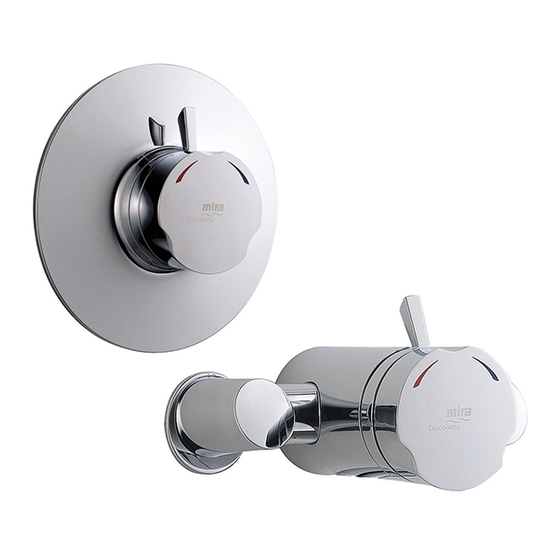
Mira Discovery Installation And User Manual
Shower valve
Hide thumbs
Also See for Discovery:
- Installation and user manual (44 pages) ,
- Installation & user manual (20 pages) ,
- Installation and user manual (25 pages)

Related Manuals for Mira Discovery


Summary of Contents for Mira Discovery
- Page 1 MIRA DISCOVERY SHOWER VALVE Installation and User Guide These instructions are to be left with the user For latest prices and delivery to your door visit MyTub Ltd - www.mytub.co.uk - info@mytub.co.uk 0844 556 1818...
-
Page 2: Table Of Contents
CONTENTS Introduction ..................... 3 Safety : Warnings ..................3 Pack Contents ..................4 Dimensions ..................... 6 Specifications ..................7 Installation Requirements ..............9 Installation ..................... 11 General ....................11 Installation Methods ................12 Exposed Shower Control ..............13 1. Rear Supplies ................13 2. -
Page 3: Introduction
INTRODUCTION The Discovery Thermostatic Shower Control with independent selection for temperature and spray force. Mira Discovery Exposed: Shower control for connection to rising, falling or rear entry pipework. Mira Discovery Built-in: Shower control for connection to concealed pipework. This product has been certified as a Type 2 valve under the BUILDCERT TMV2 scheme. -
Page 4: Pack Contents
PACK CONTENTS Tick the appropriate boxes to familiarize yourself with the Discovery Shower Control part names and to confirm that all the parts are included. Exposed Discovery Shower Control Shower Control 2 x Concealing Plates 2 x 15 mm Compression Nuts... - Page 5 Built-in Discovery Shower Control Shower Valve attached to the Building-in Shroud Control Assembly 3 x 15 mm Compression Nuts 1 x O-Key 3 x 15 mm Olives 2 x Wall Plugs 1 x Flow Regulator (12 litres per minute) 2 x Securing Screws 2.5 mm Hexagon Key...
-
Page 6: Dimensions
DIMENSIONS Exposed Discovery Shower Control Ø56 Built-in Discovery Shower Control 67 - 85 Ø183 Building-in Depth Dimensions in mm For latest prices and delivery to your door visit MyTub Ltd - www.mytub.co.uk - info@mytub.co.uk 0844 556 1818... -
Page 7: Specifications
SPECIFICATIONS Operating Parameters For Type 2 valves, the supply conditions specified in section: 'Type 2 Valves - Application' take precedence over the operating parameters which follow. Pressures Maximum Static Pressure: 10 Bar. Maximum Maintained Pressure: 5 Bar. Minimum Maintained Pressure (Gas Water Heater): 1.0 Bar. Note! For optimum performance the inlet pressures should be nominally equal and should not exceed 5:1, in favour of either supply, during flow. - Page 8 Typical Flow Rates on High Pressure Systems (with 12 Litres/Min Flow Regulator fitted in shower control outlet) - Mira Discovery with Adjustable Fittings or Rigid Head: For latest prices and delivery to your door visit MyTub Ltd - www.mytub.co.uk - info@mytub.co.uk 0844 556 1818...
-
Page 9: Installation Requirements
Note! Flow regulator recommended to be installed, refer to the ‘Discovery Fittings Installation and User Guide’. However, it is possible following installation of a flow regulator that the flow rate is reduced too much for the boiler to ignite. - Page 10 The shower can be installed with systems of this type with balanced pressures. Note! Flow regulator recommended to be installed, refer to the ‘Discovery Fittings Installation Manual’. Pumped system The shower can be installed with an inlet pump (twin impeller). The pump must be installed on the floor next to the hot water cylinder.
-
Page 11: Installation
This is to prevent back-siphonage. For further information on the installation of your shower fittings, refer Hose Retaining Ring to the Discovery Fittings Installation and User Guide. Note! Only use shower fittings recommended by the manufacturer or 25 mm Minimum supplier. -
Page 12: Installation Methods
For Rising or Falling Supplies, go to section: ‘Exposed Shower Control, 2. Rising or Falling Supplies’. Built-in Discovery Shower Control The Built-in Discovery Shower Control can be installed using Rear Fixing Points on Securing Brackets the Body, or by using the Securing Brackets... -
Page 13: Exposed Shower Control
Exposed Shower Control 1. Rear Supplies 1.1 Use the Installation Template to mark the positions of the holes for the Backplate and the pipe centres. Template Note! Allow a minimum of 150 mm either side of the Shower Control, to allow the hot and cold inlet Compression Nuts to be tightened with the Spanner supplied. - Page 14 Caution! It is essential at this point that the supply pipework is thoroughly flushed through before connection to the Shower Control. Failure to do so may result in product malfunction. 1.9 Put the Compression Nuts and Olives onto the pipework. 1.10 Remove the Elbow Shrouds from the Shower Control.
-
Page 15: Rising Or Falling Supplies
2. Rising or Falling Supplies 2.1 Remove the Elbow Shrouds from the Shower Control. 2.2 Rising Supplies: Loosen the Grubscrew on each Elbow using the 2.5 mm hexagon key (supplied) and pull off the Elbows from the Shower Control. Refit each Elbow on the opposite side and rotate 90°... - Page 16 2.7 Attach the Backplate to the wall using the Fixing Screws (supplied). Securing Screws Note! The Grubscrew should be at the bottom. Caution! It is essential at this point that the supply pipework is thoroughly flushed through before connection to Backplate the Shower Control.
-
Page 17: Built-In Shower Control
Built-in Shower Control 1. Solid Wall or Stud Partition (Using Securing Brackets - Mounting off Front Face) 1.1 Determine the route for the hot and cold supply pipework and for the outlet pipework. When connecting to the BIV Shower Fittings it is recommended that the outlet be positioned above and to one side of the Shower Control. - Page 18 1.7 Fit the Securing Brackets to the Shower Control. Backplate Important! Make sure that the correct Securing Hole holes are used, otherwise the Backplate cannot be fitted. Note! The Securing Brackets can be rotated for suitable fixing points. Backplate Rotate for Securing Hole Suitable Fixing Point...
- Page 19 1.14 Attach the Building-in Shroud to the Shower Control using the two Securing Maximum / Screws. Minimum Limits 1.15 Using the ‘Finished Wall Indicator’ on F9802 Finished Wall the Building-in Shroud as a guide, finish the wall. Caution! Make sure that the finished wall is within the maximum and minimum limits or the control components will not fit correctly.
-
Page 20: Solid Wall Or Stud Partition (Using Rear Fixing Points On Shower Control)
2. Solid Wall or Stud Partition (Using Rear Fixing Points on Shower Control) 2.1 Refer to section: ‘1. Solid Wall or Stud Partition (Using Securing Finished Wall Brackets - Mounting off Front Face)’ Surface and follow steps 1.1 to 1.4. 2.2 Cut away the plasterboard or brick work to the required depth. - Page 21 2.3 Mark the positions of the Fixing Screw Outlet Pipe to holes on the wall. Fittings Rear Fixing 2.4 For solid walls drill two 6 mm holes Point for the Wall Plugs. Securing Screw 2.5 Insert the Wall Plugs (supplied) and attach the Shower Control to the wall with the Securing Screws provided.
-
Page 22: Laminated Panels
3. Laminated Panels (Using Securing Brackets - Mounting off Rear Face) Note! For laminated panels the shower control must be positioned from the rear of the panel. Panel thickness must be between 4 and 12 mm (if a thicker panel is used, it will be necessary to recess the securing brackets into the rear of the panel). - Page 23 3.8 Fit the hot and cold supply pipes and Outlet Pipe to tighten the compression nuts. Fittings Caution! Make sure that the olives are fitted and all pipework is flushed through before connecting to the Shower Control. 3.9 Fit the outlet pipework, leaving enough pipe through the wall to temporarily cap off.
-
Page 24: Control Assembly
Control Assembly Important! The Yellow Lugs on the Flow Flow Control Control must be in the fully clockwise (off) ‘Yellow Lugs’ position in order to fit the Control Assembly. Note! The Flow Control Lugs on pre 2006 models are Black. Rotate the Temperature Knob fully clockwise and carefully pull it off. -
Page 25: Reversed Supplies
REVERSED SUPPLIES The Discovery Shower Control is supplied with inlet connections Hot-Left, Cold-Right and Bottom-Outlet as standard. If the hot and cold water supply pipes have been reversed during installation the following procedure must be performed. Isolate the hot and cold water supplies. - Page 26 11. Rotate the Cartridge 180° to reverse the inlets to the Cartridge. Caution! Make sure the two Cartridge Side Seals are not damaged. 12. Refit the Cartridge into the Shower Control Body, make sure that the lugs engage in the slots in the Body. Note! To assist in refitting the Cartridge, rotate 45°...
-
Page 27: Commissioning
Note! Make sure that any inlet isolating valves are fully open. If excessive flow rate is experienced from the Shower Control, install the supplied Flow Regulator, refer to the Discovery Fittings Installation and User Guide. Setting the Maximum Temperature Rotate the Temperature Control Knob fully clockwise (full cold position) and carefully pull it off. -
Page 28: Operation
OPERATION Shower Control (Exposed and Built-in Controls) Note! The shower performance may be effected if other water appliances are operated whilst the shower is in use. Turn the Flow Lever Anticlockwise to the Preset Maximum Flow Turn the Temperature Control Knob Clockwise to decrease the Temperature, Anticlockwise... -
Page 29: Fault Finding
Refer to Note (Too high) Refer to symptom 2. above. Note: Refer to the Discovery Fittings Installation and User Guide. For latest prices and delivery to your door visit MyTub Ltd - www.mytub.co.uk - info@mytub.co.uk 0844 556 1818... -
Page 30: Maintenance
Refer to the section ‘Maintenance, Filters’. If you require a Mira trained engineer or agent, refer to the section ‘Customer Service’. Lubricants Silicone-only based lubricants can be used to assist in refitting. - Page 31 Start Measure and record supply temperatures, pressures and make sure that they are within the valve specification. Measure and record blend temperature (Tb) and flow rate. flow rate fallen Check and clean checkvalves, significantly or fallen below strainers and outlets. minimum flow specification Measure and record blend...
-
Page 32: Filters
Filters - Exposed Models To clean or replace the inlet filters: Isolate the hot and cold water supplies. Operate the Flow Lever to drain any residual water. Remove the Elbow Shrouds. Unscrew the Filter Caps with the ‘O’ key (supplied) or a 12 mm hexagonal key. ‘O’... - Page 33 Filters - Built-in Models To clean or replace the inlet filters: Note! Refer to the section ‘Installation, Control Assembly’ for illustrations. Isolate the hot and cold water supplies. Operate the Flow Lever and Temperature Knob to drain any residual water. Rotate the Temperature Control Knob fully ‘O’...
-
Page 34: Type 2 Valves
TYPE 2 VALVES Application The approved designations for Type 2 valves are as follows: Model Designation Code Mira Discovery HP-S / LP-S The permitted application details are: Operating Mixed Water Designation Application Pressure Range Temperature °C † HP-S High Pressure Shower 41 °C maximum... - Page 35 NOTES For latest prices and delivery to your door visit MyTub Ltd - www.mytub.co.uk - info@mytub.co.uk 0844 556 1818...
- Page 36 NOTES For latest prices and delivery to your door visit MyTub Ltd - www.mytub.co.uk - info@mytub.co.uk 0844 556 1818...
- Page 37 NOTES For latest prices and delivery to your door visit MyTub Ltd - www.mytub.co.uk - info@mytub.co.uk 0844 556 1818...
-
Page 38: Spare Parts
SPARE PARTS Exposed Thermostatic Shower Control 090 95 Pipe Concealing Plates 1595 036 Temperature Hub Assembly 1595 037 Handle Pack 1595 038 Handle Adapter Pack 1595 039 Cartridge Assembly Pack 1595 040 Body Trim 1595 041 Elbow Shroud Pack (Identified ‘A’) 1595 042 Elbow Pack Assembly (Identified ‘B’) 1595 043... - Page 39 Built-in Thermostatic Shower Control 1595 036 Temperature Hub Assembly 1595 037 Handle Pack 1595 038 Handle Adapter Pack 1595 039 Cartridge Assembly Pack 1595 044 Concealing Plate Assembly 1595 046 Seal Pack (Identified ‘A’) 1595 066 Filter Pack 1595 067 Screw Pack (Identified ‘B’) 1595 070 Component Pack...
-
Page 40: Customer Service
CUSTOMER SERVICE U K A S P4924_5 © Kohler Mira Limited, May 2006 For latest prices and delivery to your door visit MyTub Ltd - www.mytub.co.uk - info@mytub.co.uk 0844 556 1818...
Need help?
Do you have a question about the Discovery and is the answer not in the manual?
Questions and answers