Table of Contents

Subscribe to Our Youtube Channel
Related Manuals for GORMAN-RUPP SFDV3B


Summary of Contents for GORMAN-RUPP SFDV3B
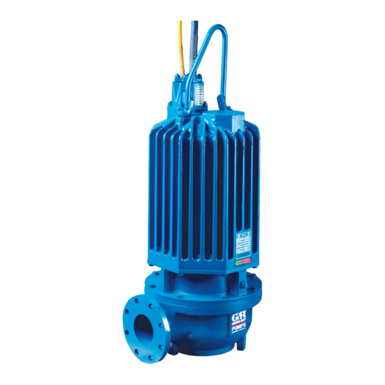
- Page 1 OM-06405-01 July 14, 2011 Rev. D 08‐15‐18 INSTALLATION, OPERATION, AND MAINTENANCE MANUAL WITH PARTS LIST SUBMERSIBLE DRY PIT PUMP MODEL SFDV3B & SFDEV3B GORMAN‐RUPP PUMPS www.grpumps.com 2016 Gorman‐Rupp Pumps Printed in U.S.A.
- Page 2 Register your new Gorman‐Rupp pump online at www.grpumps.com Valid serial number and e‐mail address required. RECORD YOUR PUMP MODEL AND SERIAL NUMBER Please record your pump model and serial number in the spaces provided below. Your Gorman‐Rupp distributor needs this information when you require parts or service. Pump Model: Serial Number:...
-
Page 3: Table Of Contents
TABLE OF CONTENTS INTRODUCTION ..........PAGE I - 1 SAFETY ‐... - Page 4 TABLE OF CONTENTS (continued) PARTS LISTS: Pump Model Assembly ..........PAGE E - 3 Motor Assemblies .
-
Page 5: Introduction
SF SERIES OM-06405 INTRODUCTION Thank You for purchasing a Gorman‐Rupp pump. HAZARD AND INSTRUCTION Read this manual carefully to learn how to safely DEFINITIONS install and operate your pump. Failure to do so could result in personal injury or damage to the The following are used to alert maintenance per... -
Page 6: Safety - Section A
SF SERIES OM-06405 SAFETY - SECTION A This information applies to the SF Se ries submersible pump indicated on the front cover of this manual. The electrical power used to operate In addition to this manual, see the sepa this pump is high enough to cause inju rate literature covering the control box, ry or death. - Page 7 OM-06405 SF SERIES to the incoming power lines. The pump electrical ground. Be sure that the in motor is designed to operate through a coming power matches the voltage and Gorman‐Rupp approved control box phase of the pump and control before which provides overload protection and connecting the power source.
- Page 8 SF SERIES OM-06405 approved by the manufacturer, can re sult in severe injury or death and void warranty. Do not remove plates, covers, gauges, pipe plugs, or fittings from an over heated pump. Vapor pressure within the pump can cause parts being disen After the pump has been installed, make gaged to be ejected with great force.
-
Page 9: Installation - Section B
SF SERIES OM-06405 INSTALLATION - SECTION B Review all SAFETY information in Section A. PUMP SEALS Since pump installations are seldom identical, this This pump is equipped with two mechanical seals. section is intended only to summarize general rec The lower seal is lubricated by the liquid being ommendations and practices required to inspect, pumped and prevents the liquid from entering the position, and arrange the pump and piping. -
Page 10: Lifting
OM-06405 SF SERIES TABLE B-1. PUMP MOTOR SPECIFICATIONS MODEL VOLTAGE/ SIZE H.P . MOTOR LOCKED PHASE LOAD ROTOR AMPS AMPS SFDV3B, SFDEV3B 208/3 3” 1750 13.80 106.1 SFDV3B, SFDEV3B 230‐460‐575/3 3” 1750 13.0/6.5/5.2 96.0/48.0/38.4 Lifting Positioning the Pump NOTE Before installing and operating the pump, check the direction of impeller rotation to ensure that the pump is properly wired at the control box. -
Page 11: Electrical Connections
SF SERIES OM-06405 keep the lines as short and straight as possible. El weight to prevent excessive strain on cable clamps bows and fittings used in a the lines increase fric and cable. tion losses; minimize their use. Dual Voltage It is recommended that a check valve or throttling valve be installed in the discharge line to control si... -
Page 12: Liquid Level Devices
OM-06405 SF SERIES Ground the control box in accordance with the in Figure B-3 and connect the pump control cable to structions accompanying it. the control box. Ground the pump to the control box using the pow er cable ground(s) and ground check wire (if so equipped). - Page 13 SF SERIES OM-06405 Liquid level devices must be positioned far Bulb (Float) Type: a bulb raises or lowers enough to allow 6 minutes between starts. (floats) with the liquid level, thus activating If the pump motor cycles more than 10 an enclosed miniature switch.
-
Page 14: Operation - Section C
SF SERIES OM-06405 OPERATION - SECTION C GENERAL INFORMATION pendent upon the quality and performance of the electrical controls, the pump warran Review all SAFETY information in Section A. ty is valid only when controls have been specified or provided by The Gorman‐ Rupp Company. - Page 15 OM-06405 SF SERIES SFDV3B 230/460/575V PERFORMANCE CURVE PAGE C - 2 OPERATION...
- Page 16 SF SERIES OM-06405 SFDV3B 208V PERFORMANCE CURVE OPERATION PAGE C - 3...
- Page 17 OM-06405 SF SERIES SFDEV3B 230/460/575V PERFORMANCE CURVE PAGE C - 4 OPERATION...
- Page 18 SF SERIES OM-06405 SFDEV3B 208V PERFORMANCE CURVE OPERATION PAGE C - 5...
-
Page 19: Control Box
OM-06405 SF SERIES Control Box 2. Lock out the power to the control panel to ensure that the pump will Control boxes are available as optional equipment remain inoperative. from the factory. The control boxes contain con 3. Allow the pump to completely cool trols for starting and stopping the pump, and pro... -
Page 20: Impeller Rotation
SF SERIES OM-06405 burns and injuries. If overheating of the ry or death. Make certain that incoming pump occurs: power is off and locked out before inter changing motor leads. 1. Stop the pump immediately. 2. Ventilate the area. 3. Allow the pump to completely cool. 4. -
Page 21: Lubrication
OM-06405 SF SERIES between starts, it will over‐heat, resulting in check for unusual noises or excessive vi damage to the motor windings. bration while the pump is running. If noise or vibration is excessive, stop operation Stopping and refer to the troubleshooting chart in the maintenance and repair manual. -
Page 22: Draining Oil
SF SERIES OM-06405 pipe plugs or fittings from an over Condition Of Oil heated pump. Vapor pressure within the Check the condition of the oil drained from the pump can cause parts being disen pump. Clear oil indicates that the pump seal(s) are gaged to be ejected with great force. -
Page 23: Troubleshooting - Section D
SF SERIES OM-06405 TROUBLESHOOTING - SECTION D Review all SAFETY information in Section A. NOTE Many of the probable remedies listed in the TROU BLESHOOTING CHART require use of electrical test instruments; for specific procedures, see ELECTRICAL TESTING at the end of the chart. TROUBLESHOOTING CHART TROUBLE POSSIBLE CAUSE... - Page 24 OM-06405 SF SERIES TROUBLESHOOTING CHART (cont'd) TROUBLE POSSIBLE CAUSE PROBABLE REMEDY Discharge head too high. Reduce discharge head or install MOTOR RUNS, BUT staging adaptor and additional PUMP FAILS TO DELIVER RATED pump. DISCHARGE. Low or incorrect voltage. Measure control box voltage, both when pump is running and when shut off.
- Page 25 SF SERIES OM-06405 ELECTRICAL TESTING 3. The pump submerged and running under full load. Make the electrical checks which follow to deter The voltage measured under each condition mine if pump malfunctions are being caused by must be the same. problems in the motor or in the motor cable.
- Page 26 OM-06405 SF SERIES motor cable green/yellow ground lead. Touch and 1 megohm, insulation is acceptable but the other test lead to each of the motor cable should be rechecked regularly. If resistance leads in turn. Note the readings. reads less than 1 megohm, insulation should be checked more closely and frequently.
-
Page 27: Pump Maintenance And Repair - Section E
SF SERIES OM-06405 PUMP MAINTENANCE AND REPAIR - SECTION E GENERAL INFORMATION cables, or the piping. Attach proper lift ing equipment to the lifting bail fitted on Review all SAFETY information in Section A. the pump. Lift the pump or component only as high as necessary and keep per... - Page 28 OM-06405 SF SERIES ILLUSTRATION PARTS PAGE Figure E-1. SFDV3B & SFDEV3B Pump Model Assembly PAGE E - 2 MAINTENANCE AND REPAIR...
- Page 29 SF SERIES OM-06405 SFDV3B & SFDEV3B Pump Model Assembly Parts List (From S/N 1520902 Up) If your pump serial number is followed by an “N”, your pump is NOT a standard production model. Contact the Gorman‐Rupp Company to verify part numbers.
- Page 30 OM-06405 SF SERIES ILLUSTRATION Figure E-2. 47111-802, -806 and -807 Motor Assemblies PAGE E - 4 MAINTENANCE AND REPAIR...
- Page 31 SF SERIES OM-06405 47111-802, -806 and -807 Motor Assemblies Parts List ITEM PART NAME PART ITEM PART NAME PART NUMBER NUMBER MOTOR SUBASSEMBLY INTERMEDIATE 38261-033 10000 -208‐230/3 47111-832 SEAL ASSY S1832 --MOTOR HOUSING 38311-066 10000 SNAP RING S362 --STATOR 47113-091 LOCK WASHER MJ10 17000 --TERMINAL HSG STUD MC1042 17000...
- Page 32 OM-06405 SF SERIES PUMP AND SEAL DISASSEMBLY AND the pump. Lift the pump or component only as high as necessary and keep per REASSEMBLY sonnel away from suspended objects. Review all SAFETY information in Section A. This pump requires little service due to its rugged, minimum‐maintenance design.
- Page 33 Remove the O‐ring (15) from the outer shoulder of the seal plate (14). Use Only Genuine Gorman-Rupp re placement parts. Failure to do so may cre Draining Oil From Seal Cavity ate a hazard and damage the pump or di...
- Page 34 OM-06405 SF SERIES Remove the impeller washer (3). Remove the metal Remove the seal retaining ring (10) using snap ring rod from between the vanes of the impeller. pliers. Use caution when removing the retaining ring; tension on the seal spring will be released. To remove the impeller, use two thin‐bladed screw...
- Page 35 SF SERIES OM-06405 Thoroughly clean all reuseable parts with a soft Neither of the shaft seal assemblies should be re cloth soaked in cleaning solvent. Remove all O‐ used because wear patterns on the finished faces rings and clean the sealing surfaces. cannot be realigned during reassembly.
- Page 36 OM-06405 SF SERIES Upper Seal Installation Apply a light coating of oil to the seal seating sur face on the shaft, the groove for the retaining ring (Figures E-2 and E-3) (10) and I.D. of the bellows. Position the seal rotat ing portion on the shaft with the seal face down.
- Page 37 SF SERIES OM-06405 push the impeller onto the shaft until seated firmly NOTE against the upper impeller shim set. If the seal plate was not removed during disassem bly, cover the stationary element with a clean tissue A clearance of .020 to .040 inch (0,51 to 1,02 mm) and use your thumbs to press the seal stationary between the impeller and the seal plate is recom...
- Page 38 OM-06405 SF SERIES tor be returned to Gorman‐Rupp, or to a Gorman‐ responding housing on each of the stator leads. Rupp authorized Submersible Repair Center. Carefully pull each of the cable lead housings apart from its corresponding stator lead housing and re move the terminal housing assembly from the pump.
- Page 39 SF SERIES OM-06405 removed, position the motor housing upside down on a flat work surface. Position an expandable tool, such as a split disc, Most cleaning solvents are toxic and approximately 2 inches (51 mm) down inside the stator and expand it tightly and squarely on the I.D. flammable.
- Page 40 OM-06405 SF SERIES is strongly recommended that new O‐rings and height when assembled. shaft seal assemblies be used during reassembly (see the parts list for numbers). The O.D. of the stator must be painted with GE Glyptal insulating paint just prior to being installed Stator Installation in the motor housing.
- Page 41 SF SERIES OM-06405 the intermediate until fully seated. If removed, install a new male terminal (15) on the sensor and position it so the moisture sensor female terminal (14) can be easily attached. Use caution when handling hot bear ings to prevent burns. Inspect the rotor shaft (3) for damaged threads, If heating the bearings is not practical, use a suit...
- Page 42 OM-06405 SF SERIES With the motor housing and stator positioned up tilated area free from excessive heat, side down, carefully lower the assembled inter sparks, and flame. Read and follow all mediate, rotor shaft and bearings into the motor precautions printed on solvent contain housing until the female terminal (14) can be se...
- Page 43 SF SERIES OM-06405 Hoisting Bail Installation motor and seal cavities must be vacuum tested any time the seal(s) and/or motor are serviced. (Figure E-1) Use a manometer with a range of 30 to 0 to 30 inch es of mercury to perform the test. Do not use a vac If the hoisting bail (13) was removed in order to re...
- Page 44 OM-06405 SF SERIES ential between the vacuum readings shown in the ing assembly must be replaced with a test plate. table. Make the test plate as shown in Figure E-5 below, install the terminal housing O‐ring under the test To vacuum test the motor cavity, the terminal hous plate, then proceed with vacuum testing.
- Page 45 SF SERIES OM-06405 The grade of lubricant used is critical to the opera tion of this pump. Use premium quality hydraulic oil as specified in Table E-2. Table E-2. Pump Oil Specifications Specifications: Type ......Premium high viscosity index, anti‐wear hydraulic oil Viscosity (SSU @ 104_F [40_C]) .
- Page 46 For Warranty Information, Please Visit www.grpumps.com/warranty or call: U.S.: 419-755-1280 Canada: 519-631-2870 International: +1-419-755-1352 GORMAN‐RUPP PUMPS...
Need help?
Do you have a question about the SFDV3B and is the answer not in the manual?
Questions and answers