
Subscribe to Our Youtube Channel
Related Manuals for GORMAN-RUPP SFS4A


Summary of Contents for GORMAN-RUPP SFS4A
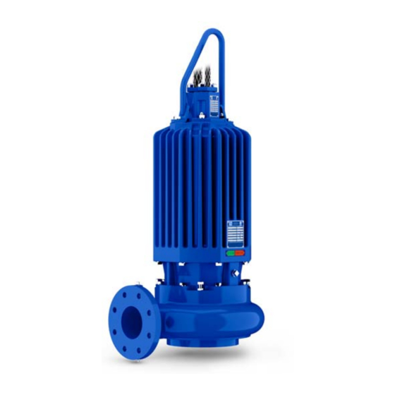
- Page 1 OM-06791-02 August 8, 2022 INSTALLATION, OPERATION, AND MAINTENANCE MANUAL WITH PARTS LIST SUBMERSIBLE PUMP MODEL SFS4A GORMAN‐RUPP PUMPS www.grpumps.com 2022 Gorman‐Rupp Pumps Printed in U.S.A.
- Page 2 Register your new Gorman‐Rupp pump online at www.grpumps.com Valid serial number and e‐mail address required. RECORD YOUR PUMP MODEL AND SERIAL NUMBER Please record your pump model and serial number in the spaces provided below. Your Gorman‐Rupp distributor needs this information when you require parts or service. Pump Model: Serial Number:...
-
Page 3: Table Of Contents
TABLE OF CONTENTS INTRODUCTION ..........PAGE I - 1 SAFETY ‐... - Page 4 TABLE OF CONTENTS (continued) PARTS LISTS: Pump Model Assembly ..........PAGE E - 3 Motor Assemblies .
-
Page 5: Introduction
SF SERIES OM-06791 INTRODUCTION Thank You for purchasing a Gorman‐Rupp pump. HAZARD AND INSTRUCTION Read this manual carefully to learn how to safely DEFINITIONS install and operate your pump. Failure to do so could result in personal injury or damage to the The following are used to alert maintenance per... -
Page 6: Safety - Section A
SF SERIES OM-06791 SAFETY - SECTION A This information applies to the SF Se ries submersible pump indicated on the front cover of this manual. The electrical power used to operate In addition to this manual, see the sepa this pump is high enough to cause inju rate literature covering the control box, ry or death. - Page 7 OM-06791 SF SERIES to the incoming power lines. The pump motor is designed to operate through a Gorman‐Rupp approved control box which provides overload protection and power control; otherwise, the pump The electrical power used to operate warranty will be voided. Make certain this pump is high enough to cause inju...
- Page 8 SF SERIES OM-06791 Do not remove plates, covers, gauges, After the pump has been installed, make pipe plugs, or fittings from an over certain that the pump and all piping or heated pump. Vapor pressure within the pump can cause parts being disen hose connections are secure before op...
-
Page 9: Installation - Section B
SF SERIES OM-06791 INSTALLATION - SECTION B Review all SAFETY information in Section A. match the ratings on the control box and in coming power. Since pump installations are seldom identical, this e. Carefully read all tags, decals, and markings section is intended only to summarize general rec... -
Page 10: Lifting
SF SERIES See Table B-1 for motor specifications. TABLE B-1. PUMP MOTOR SPECIFICATIONS MODEL VOLTAGE/ SIZE H.P . MOTOR LOCKED PHASE LOAD ROTOR AMPS AMPS SFS4A 208/3 4” 10.0 1750 30.0 184.7 SFS4A 208/3 4” 12.5 1750 36.6 184.7 SFS4A 230‐460‐575/3... -
Page 11: Electrical Connections
SF SERIES OM-06791 Either hose or rigid pipe may be used to make dis TABLE B-2. MOTOR VOLTAGE LIMITS charge connections. The discharge line must be NOMINAL PHASE MINIMUM MAXIMUM independently supported to avoid vibration and VOLTAGE VOLTAGE VOLTAGE strain on the pump. For maximum pumping capac ity, keep the line as short and straight as possible. -
Page 12: Control Box Connections
OM-06791 SF SERIES lead (s). Connect the second test lead to an unin sulated point on the pump body. The test circuit should close. If the test circuit does not close, there is a defect in the cable or motor which must be corrected. Control Box Connections The pump warranty is void if the motor is not operated through a control box ap... -
Page 13: Liquid Level Devices
SF SERIES OM-06791 Liquid Level Devices phragm which flexes with changes in liquid level, thus activating an enclosed miniature switch. Optional controls available from Gorman‐Rupp may provide a means to automatically regulate the Bulb (Float) Type: a bulb raises or lowers liquid level. -
Page 14: Operation - Section C
SF SERIES OM-06791 OPERATION - SECTION C GENERAL INFORMATION pendent upon the quality and performance of the electrical controls, the pump warran Review all SAFETY information in Section A. ty is valid only when controls have been specified or provided by The Gorman‐ Rupp Company. - Page 15 OM-06791 SF SERIES SFS4A 230/460/575V 3P PERFORMANCE CURVE PAGE C - 2 OPERATION...
- Page 16 SF SERIES OM-06791 SFS4A 208V 3P PERFORMANCE CURVE OPERATION PAGE C - 3...
-
Page 17: Control Box
OM-06791 SF SERIES Control Box 2. Lock out the power to the control panel to ensure that the pump will Control boxes are available as optional equipment remain inoperative. from the factory. The control boxes contain con 3. Allow the pump to completely cool trols for starting and stopping the pump, and pro... -
Page 18: Impeller Rotation
SF SERIES OM-06791 burns and injuries. If overheating of the ry or death. Make certain that incoming pump occurs: power is off and locked out before inter changing motor leads. 1. Stop the pump immediately. 2. Ventilate the area. 3. Allow the pump to completely cool. 4. - Page 19 OM-06791 SF SERIES between starts, it will over‐heat, resulting in damage to the motor windings. Stopping To avoid serious damage to the pump, check for unusual noises or excessive vi bration while the pump is running. If noise Follow the instructions accompanying the control or vibration is excessive, stop operation box for stopping the pump.
-
Page 20: Cold Weather Preservation
SF SERIES OM-06791 COLD WEATHER PRESERVATION first two weeks of operation, and every month thereafter. Before installing or removing the lubrication plugs, always clean the area around the plugs to prevent contamination. Do not attempt to thaw the pump by us Draining Oil ing a torch or other source of flame. -
Page 21: Troubleshooting - Section D
SF SERIES OM-06791 TROUBLESHOOTING - SECTION D Review all SAFETY information in Section A. NOTE Many of the probable remedies listed in the TROU BLESHOOTING CHART require use of electrical test instruments; for specific procedures, see ELECTRICAL TESTING at the end of the chart. TROUBLESHOOTING CHART TROUBLE POSSIBLE CAUSE... - Page 22 OM-06791 SF SERIES TROUBLESHOOTING CHART (cont'd) TROUBLE POSSIBLE CAUSE PROBABLE REMEDY Discharge head too high. Reduce discharge head or install MOTOR RUNS, BUT staging adaptor and additional PUMP FAILS TO DELIVER RATED pump. DISCHARGE. Low or incorrect voltage. Measure control box voltage, both when pump is running and when shut off.
- Page 23 SF SERIES OM-06791 ELECTRICAL TESTING 3. The pump submerged and running under full load. Make the electrical checks which follow to deter The voltage measured under each condition mine if pump malfunctions are being caused by must be the same. problems in the motor or in the motor cable.
- Page 24 OM-06791 SF SERIES motor cable green/yellow ground lead. Touch and 1 megohm, insulation is acceptable but the other test lead to each of the motor cable should be rechecked regularly. If resistance leads in turn. Note the readings. reads less than 1 megohm, insulation should be checked more closely and frequently.
-
Page 25: Pump Maintenance And Repair - Section E
SF SERIES OM-06791 PUMP MAINTENANCE AND REPAIR - SECTION E GENERAL INFORMATION Review all SAFETY information in Section A. The maintenance and repair instructions in this manual are keyed to the illustrations, Figures E-1 and E-2, and the corresponding parts lists. Select a suitable location, preferably indoors, to Death or serious personal injury and perform required maintenance. - Page 26 OM-06791 SF SERIES ILLUSTRATION PARTS PAGE Figure E-1. SFS4A Pump Model Assembly PAGE E - 2 MAINTENANCE AND REPAIR...
- Page 27 SF SERIES OM-06791 SFS4A Pump Model Assembly Parts List (From S/N 1812090 Up) If your pump serial number is followed by an “N”, your pump is NOT a standard production model. Contact the Gorman‐Rupp Company to verify part numbers. ITEM...
- Page 28 OM-06791 SF SERIES ILLUSTRATION Figure E-2. Motor Assemblies PAGE E - 4 MAINTENANCE AND REPAIR...
- Page 29 SF SERIES OM-06791 Motor Assemblies Parts List ITEM PART PART NAME NUMBER STATOR/HOUSING SUBASSEMBLY -208‐230V/3P , 460V/3P 47113-113 --MOTOR HOUSING 38311-067 10000 --STATOR 47113-093 --TERMINAL HOUSING STUD MC1042 17000 --ROTATION DECAL 38815-027 -575V/3P 47113-114 --MOTOR HOUSING 38311-067 10000 --STATOR 47113-094 --TERMINAL HOUSING STUD MC1042 17000 --ROTATION DECAL...
- Page 30 OM-06791 SF SERIES PUMP AND SEAL DISASSEMBLY AND the pump. Lift the pump or component only as high as necessary and keep per REASSEMBLY sonnel away from suspended objects. Review all SAFETY information in Section A. This pump requires little service due to its rugged, minimum‐maintenance design.
- Page 31 Remove the hardware (9 and 16) securing the motor assembly (13) to the pump casing (1). Use Only Genuine Gorman-Rupp re placement parts. Failure to do so may cre Using the lifting device, raise the motor assembly ate a hazard and damage the pump or di...
- Page 32 OM-06791 SF SERIES condition which could indicate lower seal failure or Remove the seal sleeve O‐ring (21) from the rotor poor O‐ring seal. shaft. If no further disassembly is required, proceed to Impeller Removal the appropriate areas in PUMP END REASSEMB (Figure E-1) Upper Seal Removal Wedge a soft metal rod between the impeller vanes...
- Page 33 SF SERIES OM-06791 reassemble the pump end components at this time. tilated area free from excessive heat, sparks, and flame. Read and follow all precautions printed on solvent contain PUMP END REASSEMBLY ers. Inspect the rotor shaft (3, Figure E-2) for dam NOTE aged threads, scoring, or nicks.
- Page 34 OM-06791 SF SERIES ROTOR STATIONARY SHAFT SEAL SEAT ROTATING O‐RING ELEMENT SPRING BELLOWS AND RETAINER ASSY SPRING CENTERING WASHER SEAL RETAINING RING STATIONARY SEAL PLATE SEAL SEAT O‐RING ROTATING BELLOWS AND ELEMENT RETAINER ASSY SPRING SHIM SET SPRING RETAINER IMPELLER Figure E-3.
- Page 35 SF SERIES OM-06791 Position the intermediate so the holes for the Lubricate the seal sleeve O‐ring (21) with light oil mounting hardware in the intermediate align with and slide it onto the rotor shaft until it is seated those in the motor housing and press the inter against the shaft shoulder.
- Page 36 OM-06791 SF SERIES Lubricate the I.D. of the bellows with water and Position the replacement wear plate in the pump slide the rotating subassembly over the shaft casing bore and align the wear plate studs with the sleeve (23) until the seal face is just flush with the corresponding holes in the casing.
- Page 37 SF SERIES OM-06791 If installed in a trash application, secure the pump and 10) and separate the bail from the motor hous to the trash stand with the previously removed ing. hardware. If the discharge elbow was removed, re place the gasket and secure the discharge elbow Terminal Housing Assembly Removal to the pump casing with the previously remove (Figure E-1)
- Page 38 OM-06791 SF SERIES Remove the snap ring (4) from the groove in the in Stator Removal termediate and pull the assembled rotor shaft and (Figure E-2) bearings out of the intermediate. Stator replacement requires specialized To prevent damage during removal from equipment, experience with electric mo...
- Page 39 SF SERIES OM-06791 MOTOR REASSEMBLY precautions printed on solvent contain ers. After the motor housing is thoroughly cleaned, po sition it on a flat surface and secure it in an inverted position. Do not unwrap the stator until the motor housing has been prepared for stator installation.
- Page 40 OM-06791 SF SERIES oil and the container must be absolutely clean. If terminal housing opening. Carefully lower the sta the oil has been previously used, it must be thor tor into the motor housing until fully seated against oughly filtered. the housing shoulder.
- Page 41 SF SERIES OM-06791 precautions printed on solvent contain vices of a qualified electrician to make ers. electrical connections. Position the intermediate with the impeller end Secure the pump in upright position with the hoist down on some wood blocks tall enough to allow for ing bail and terminal housing assembly removed.
- Page 42 OM-06791 SF SERIES Hoisting Bail Installation motor and seal cavities must be vacuum tested any time the seal(s) and/or motor are serviced. (Figure E-1) Use a manometer with a range of 30 to 0 to 30 inch es of mercury to perform the test. Do not use a vac If the hoisting bail (11) was removed in order to re...
- Page 43 SF SERIES OM-06791 ential between the vacuum readings shown in the ing assembly must be replaced with a test plate. table. Make the test plate as shown in Figure E-5 below, install the terminal housing O‐ring under the test To vacuum test the motor cavity, the terminal hous plate, then proceed with vacuum testing.
- Page 44 OM-06791 SF SERIES The grade of lubricant used is critical to the opera tion of this pump. Use premium quality hydraulic oil as specified in Table E-2. Table E-2. Pump Oil Specifications Specifications: Type ......Premium high viscosity index, anti‐wear hydraulic oil Viscosity (SSU @ 104_F [40_C]) .
- Page 45 For Warranty Information, Please Visit www.grpumps.com/warranty or call: U.S.: 419-755-1280 Canada: 519-631-2870 International: +1-419-755-1352 GORMAN‐RUPP PUMPS...
Need help?
Do you have a question about the SFS4A and is the answer not in the manual?
Questions and answers