Table of Contents

Subscribe to Our Youtube Channel
Related Manuals for GORMAN-RUPP S8D1-E275 460/3


Summary of Contents for GORMAN-RUPP S8D1-E275 460/3
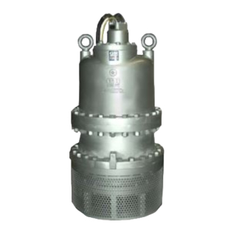
- Page 1 OM‐07089‐04 April 5, 2017 Rev. B - 5/29/19 INSTALLATION, OPERATION, AND MAINTENANCE MANUAL WITH PARTS LIST SUBMERSIBLE PUMP MODEL S8D1-E275 460 & 575/3 GORMAN‐RUPP PUMPS www.grpumps.com 2017 Gorman‐Rupp Pumps Printed in U.S.A.
- Page 2 Register your new Gorman‐Rupp pump online at www.grpumps.com Valid serial number and e‐mail address required. RECORD YOUR PUMP MODEL AND SERIAL NUMBER Please record your pump model and serial number in the spaces provided below. Your Gorman‐Rupp distributor needs this information when you require parts or service. Pump Model: Serial Number:...
-
Page 3: Table Of Contents
TABLE OF CONTENTS INTRODUCTION ..........PAGE I - 1 SAFETY ‐... - Page 4 TABLE OF CONTENTS (continued) PARTS LISTS: Pump Assembly ............PAGE E - 3 Terminal Housing and Cable Assemblies .
-
Page 5: Introduction
S SERIES PUMPS OM-07089 INTRODUCTION Thank You for purchasing a Gorman‐Rupp pump. HAZARD AND INSTRUCTION Read this manual carefully to learn how to safely DEFINITIONS install and operate your pump. Failure to do so could result in personal injury or damage to the The following are used to alert maintenance per... -
Page 6: Safety - Section A
OM-07089 S SERIES PUMPS SAFETY - SECTION A This information applies to the S Series submersible motor driven pumps indi cated on the front cover of this manual. Before connecting any cable to the con Because pump installations are seldom trol box, be sure to ground the control identical, this manual cannot possibly box. - Page 7 S SERIES PUMPS OM-07089 position and locked out, or that the pow and the pump or components will not be er supply to the control box has been damaged when lifting. Do not attempt to otherwise cut off and locked out, before lift this pump by the motor or control attempting to open or service the pump cables, or the piping.
- Page 8 OM-07089 S SERIES PUMPS low the pump to completely cool before lift it, make certain that they are posi servicing. tioned so as not to damage the pump, and so that the load will be balanced. Do not attempt to lift the pump by the motor power cable or the piping.
-
Page 9: Installation - Section B
OM-07089 S SERIES PUMPS INSTALLATION - SECTION B GENERAL INFORMATION ratings on the control box and incoming pow Review all SAFETY information in Section A. e. Carefully read all tags, decals, and markings Since pump installations are seldom identical, this on the pump, and perform all duties indicated. -
Page 10: Pump Motor Specifications
OM-07089 S SERIES PUMPS equipment as outlined in the National to prevent liquid from wicking through the Electric Code. Follow all safety require cable and into the motor. ments. Failure to observe these require NOTE ments could result in injury or death to Refer to the performance curve in Maintenance personnel. -
Page 11: Positioning The Pump
OM-07089 S SERIES PUMPS lift this pump by the motor or control are fitted with a pressure relief valve which will open if vapor pressure within the pump motor reaches a cables, or the piping. Attach proper lift critical point. ing equipment to the lifting bail fitted on the pump. -
Page 12: Electrical Connections
OM-07089 S SERIES PUMPS pump, allowing one pump to feed the other on high The control box is a rainproof enclosure with a pad discharge head applications. lockable front cover. The enclosure is not de signed to be watertight, and should not be sub To determine the size of the discharge connection, merged. -
Page 13: Grounding Methods
OM-07089 S SERIES PUMPS erly grounded. Install and operate the Table B‐3. Pump Voltage Requirements control box in accordance with the Na MAXIMUM tional Electric Code and all local codes. NOMINAL MINIMUM PHASE VOLTAGE VOLTAGE VOLTAGE Failure to follow these could result in in jury or death to personnel. -
Page 14: Pump Power Cable Connections
OM-07089 S SERIES PUMPS b. Driven Electrode: A rod or pipe, 3/4 inch (19,1 mm) in diameter minimum, 8 feet (2,4 m) long, completely driven into the ground. The electrical power used to operate c. Buried electrode: If rock or stone prevents this pump is high enough to cause inju... -
Page 15: Control Box Specifications
OM-07089 S SERIES PUMPS Connect the pump power cable to the control box NOTE as shown in the wiring diagrams in the control box For reference, internal motor wiring connections manual. Use conduit or cable clamps to secure the are shown in Maintenance and Repair - Section power cable to the control box. -
Page 16: Wiring Diagrams
OM-07089 S SERIES PUMPS PUMP PUMP CONTROL BOX CONTROL BOX TO LEVEL CONTROL CIRCUIT TO LEVEL CONTROL CIRCUIT IN MAIN CONTROL BOX IN MAIN CONTROL BOX LIQUID LEVEL LIQUID LEVEL RANGE RANGE DEWATERING DEWATERING ON (FILLING) ON (FILLING) BULB (FLOAT TYPE) DIAPHRAGM TYPE Figure B-4. -
Page 17: Operation - Section C
S SERIES PUMPS OM-07089 OPERATION - SECTION C GENERAL INFORMATION Review all SAFETY information in Section A. The pump motor and control box are not designed to be explosion‐proof. Do not operate in an explosive atmosphere. Any control box used to operate the This pump is designed to handle most pump must be approved by the Gor... -
Page 18: Impeller Rotation
OM-07089 S SERIES PUMPS or thermal protection, or if the pump is operated 4. Check the temperature before ser against a closed discharge valve for an extended vicing. period of time. 5. Vent the pump slowly and cau tiously 6. Refer to instructions in this manual before restarting the pump. -
Page 19: Starting, Stopping And Operational Checks
S SERIES PUMPS OM-07089 this pump is high enough to cause inju ry or death. Make certain that incoming power is off and locked out before inter changing motor leads. Never start the pump more than 6 times per hour. If the pump motor does not cool be tween starts, it will over‐heat, resulting in damage to the motor windings. -
Page 20: Cold Weather Preservation
OM-07089 S SERIES PUMPS COLD WEATHER PRESERVATION To avoid serious damage to the pump, check for unusual noises or excessive vi Do not attempt to thaw the pump by us bration while the pump is running. If noise ing a torch or other source of flame. This or vibration is excessive, stop operation could damage gaskets, O‐rings or heat and refer to the troubleshooting chart in the... -
Page 21: Draining Oil
S SERIES PUMPS OM-07089 month thereafter. Check the motor lubrication level Adding Oil any time the pressure relief valve is activated, and Refer to Table B-2 in INSTALLATION for oil ca replace the oil annually. pacities and positions for filling the seal cavity in your pump. - Page 22 OM-07089 S SERIES PUMPS Table C-1. Pump Oil Specifications Specifications: Type ......Premium high viscosity index, anti‐wear hydraulic oil Viscosity @ 100_F (38_C) .
-
Page 23: Troubleshooting - Section D
OM-07089 S SERIES PUMPS TROUBLESHOOTING - SECTION D Review all SAFETY information in Section A. NOTE Many of the probable remedies listed in the TROU BLESHOOTING CHART require use of electrical test instruments; for specific procedures, see ELECTRICAL TESTING at the end of the chart. TROUBLESHOOTING CHART TROUBLE POSSIBLE CAUSE... - Page 24 S SERIES PUMPS OM-07089 TROUBLESHOOTING CHART (cont'd) TROUBLE POSSIBLE CAUSE PROBABLE REMEDY Discharge head too high. Reduce discharge head or install MOTOR RUNS, BUT PUMP FAILS staging adaptor and additional TO DELIVER pump. RATED DIS Low or incorrect voltage. Measure control box voltage, both CHARGE.
- Page 25 OM-07089 S SERIES PUMPS ELECTRICAL TESTING 3. The pump submerged and running under full load. Make the electrical checks which follow to deter The voltage measured under each condition mine if pump malfunctions are being caused by must be the same. problems in the motor or in the motor cable.
- Page 26 S SERIES PUMPS OM-07089 the other test lead to each of the motor cable should be rechecked regularly. If resistance leads in turn. Note the readings. reads less than 1 megohm, insulation should be checked more closely and frequently. b. Readings will indicate resistance values in both the power cable and motor windings.If resistance reads infinity (1), insulation is c.
-
Page 27: Pump Maintenance And Repair - Section E
MAINTENANCE AND REPAIR OF THE WEARING PARTS OF THE PUMP WILL MAINTAIN PEAK OPERATING PERFORMANCE. STANDARD PERFORMANCE FOR PUMP MODELS S8D1-E275 460/3 & 575/3 Based on 70_F (21_C) clear water at sea level Contact the Gorman‐Rupp Company to verify per... - Page 28 S SERIES PUMPS OM-07089 ILLUSTRATION PARTS PAGE Figure E-1. S8D1-E275 460/3 & 575/3 Pump Assembly PAGE E - 2 MAINTENANCE AND REPAIR...
- Page 29 OM-07089 S SERIES PUMPS Parts List Pump Model S8D1-E275 460/3 & 575/3 (From S/N 1654719 Up) ITEM PART NAME PART ITEM PART NAME PART NUMBER NUMBER BASE PLATE ASSY 41582-001 2415V HEX HEAD CAP SCREW B0812 15991 LOCK WASHER J08 15991...
- Page 30 S SERIES PUMPS OM-07089 ILLUSTRATION PARTS PAGE Figure E-2. S8D1-E275 460/3 & 575/3 Pump Assembly (con't) PAGE E - 4 MAINTENANCE AND REPAIR...
- Page 31 OM-07089 S SERIES PUMPS Parts List Pump Model S8D1-E275 460/3 & 575/3 (From S/N 1654719 Up) ITEM PART NAME PART ITEM PART NAME PART NUMBER NUMBER BASE PLATE ASSY 41582-001 2415V HEX HEAD CAP SCREW B0812 15991 LOCK WASHER J08 15991...
- Page 32 S SERIES PUMPS OM-07089 ILLUSTRATION Figure E-3. Terminal Housing And Cable Assembly PAGE E - 6 MAINTENANCE AND REPAIR...
- Page 33 OM-07089 S SERIES PUMPS Terminal Housing And Cable Assembly Parts List ITEM PART PART NAME NUMBER CABLE #2/0 X 50 FT. LG. 10325A CABLE GRIP 11227F STUD C0808 15991 HEX NUT D08 15991 TERMINAL GLAND 10658 13040 GLAND BUSHING 10758E 19100 TERMINAL WASHER 10659B 15991 TERMINAL HOUSING...
- Page 34 S SERIES PUMPS OM-07089 used, disconnect the piping before attempting to PUMP AND SEAL DISASSEMBLY AND move the pump. REASSEMBLY Review all SAFETY information in Section A. Death or serious personal injury and damage to the pump or components can occur if proper lifting procedures Do not attempt to service the pump as...
- Page 35 OM-07089 S SERIES PUMPS Draining Oil From Seal And Motor Cavity assembly. Tag electrical circuits to pre vent accidental start‐up. (Figure E-2) If any further disassembly is to be performed on the pump, the seal and motor oil cavities must be drained.
- Page 36 S SERIES PUMPS OM-07089 ing the pump is not practical, lay the pump on its Suction Head And Wear Ring Removal side and secure it to prevent rolling. (Figure E-1) Remove the hardware (28 and 29) securing the 1.5” DIA. DRILL suction head (4) to the first stage diffuser (8).
- Page 37 OM-07089 S SERIES PUMPS Second Stage Diffuser and Wear Ring Removal Lower Seal Removal (Figures E-2 and E-6) (Figure E-1 & E-2) Carefully remove the seal spring. Lubricate the ro Disengage the hardware (14 and 15) and separate tor shaft (40) and work oil under the bellows as the second stage diffuser (23) and gaskets (19 and sembly.
- Page 38 S SERIES PUMPS OM-07089 Lubricate the rotor shaft (40) and work oil under the Thoroughly clean all reuseable parts with a soft bellows. Position a screwdriver or other suitable cloth soaked in cleaning solvent. Remove all O‐ device on each side of the bellows retaining flange, rings and gaskets, and clean the sealing surfaces and pry the bellows upward until the rotating por...
- Page 39 OM-07089 S SERIES PUMPS ROTOR O‐RING SHAFT F.H. SCREW INTERMEDIATE STATIONARY RETAINING RING SEAT BELLOWS AND ROTATING RETAINING ASSY ELEMENT SPRING SEAL SPRING RETAINING RING RETAINER O‐RING SEAL PLATE STATIONARY STATIONARY SEAL SEAT ELEMENT ROTATING BELLOWS AND ELEMENT RETAINING ASSY SPRING IMPELLER KEY IMPELLER...
- Page 40 S SERIES PUMPS OM-07089 surface damage. Because the rotating element sure that the grooves in the element engage the may not stay in the bellows retainer when turned lugs on the seat. Apply a light coating of oil to the upside down, place a small amount of grease at seal plate bore and the outer O‐ring.
- Page 41 OM-07089 S SERIES PUMPS pressure on the bellows retainer until it slides down 20), and position the diffuser against the intermedi the shaft and the seal faces contact. ate (47). Apply `Never‐Seez' or equivalent com pound to the threads of the capscrews and studs Slide the seal spring over the shaft and bellows re...
- Page 42 S SERIES PUMPS OM-07089 the diffuser, the shaft and lower bearing have been See LUBRICATION and FINAL ASSEMBLY be driven out of position during impeller removal. If this fore putting the pump back into service. occurs, the lower bearing must be pressed back into place (see MOTOR DISASSEMBLY and MO...
- Page 43 OM-07089 S SERIES PUMPS Secure the pump in an upright position. Remove If it is necessary to replace the terminal plate (21) or the hex locknuts (66) securing the terminal hous terminal components, unscrew the terminal collars ing assembly to the motor housing assembly (70). (14), and remove the terminal posts (17) and dyna seal washers (15) from the terminal plate (21).
- Page 44 S SERIES PUMPS OM-07089 Use a suitable lifting device to hoist the intermedi ate, rotor and shaft assembly (40) and ball bear ings (41 and 46) from the motor housing as an as sembly. If necessary, use a soft‐faced mallet to Most cleaning solvents are toxic and break the seal between the intermediate and the flammable.
- Page 45 OM-07089 S SERIES PUMPS motor housing, and “walk” the stator out. Continue Stator Installation this process until the stator clears the motor hous (Figure E-2) ing. NOTE Stator installation involves heating the motor hous ing. This process must be done quickly. Therefore it is recommended that these steps be performed by Take care not to damage the stator end two people to promote efficient installation of the...
- Page 46 S SERIES PUMPS OM-07089 tightly and squarely on the I.D. Attach a lifting de vice to the lifting eye of the tool, and carefully lift the assembly. Take care not to damage the stator end turns. Slip a sleeve over the stator leads, or tape To prevent damage during removal from them together to protect them during installation.
- Page 47 OM-07089 S SERIES PUMPS pound to the O. D. of the bearing (41) and bearing Heat the bearing and bearing cap assembly. With cap (44). The bearing must be installed in the bear the impeller end of the shaft up, slide the bearing ing cap before assembling the bearing on the and bearing cap onto the shaft until it seats square...
- Page 48 S SERIES PUMPS OM-07089 Refer to PUMP END REASSEMBLY, and reas cables, allowing approximately 3 ft. (1 m) of each semble the pump end components. cable to extend beyond the terminal housing. Tem porarily tape the green and yellow ground wires to the cables.
- Page 49 OM-07089 S SERIES PUMPS supplemented with two gaskets contained in the number) or potting compound for sealing overhaul gasket kit (see Options listed in the Parts terminal housing connections. Use of un List). approved sealing products will void the pump warranty. NOTE Clean the cable leads and terminal plate in the NOTE...
- Page 50 S SERIES PUMPS OM-07089 Figure E-9. Terminal Housing Wiring Connections Sealing Terminal Housing Connections Trim the potting mold so it is just long enough to With Potting Compound cover the terminal collars. Slide the potting mold up over the leads of the power cable and control (Figure E-3) cable.
- Page 51 OM-07089 S SERIES PUMPS Before installing the terminal housing, group the ings and recommendations accompa motor leads together in the upper motor housing, nying the potting kit. and secure them with a cable tie. See the instructions with the potting kit regarding Slide a length of heat‐shrink tubing (not shown) application life and setting and curing time.
- Page 52 S SERIES PUMPS OM-07089 cavities will be drawn into the system, resulting in FINAL ASSEMBLY damage to the vacuum pump or manometer. (Figure E-2) Use a manometer with a range of 30 to 0 to 30 inch es of mercury to perform the test. Do not use a vac If removed, install the lifting eyes (68) in the motor uum gauge.
- Page 53 OM-07089 S SERIES PUMPS Table E-1. Vacuum Test Data Pump Duration Seal Cavity Duration Motor Cavity Model (Minutes) Vacuum (Minutes) Vacuum (In. Hg.) (In. Hg.) LUBRICATION If the oil level is abnormally low, or if the oil contains water, dirt, or appears cloudy, the lower seal or gaskets may require replacement.
- Page 54 S SERIES PUMPS OM-07089 Table E-3. Pump Oil Specifications Specifications: Type ......Premium high viscosity index, anti‐wear hydraulic oil Viscosity (SSU @ 104_F [40_C]) .
- Page 55 For Warranty Information, Please Visit www.grpumps.com/warranty or call: U.S.: 419-755-1280 Canada: 519-631-2870 International: +1-419-755-1352 GORMAN‐RUPP PUMPS...
Need help?
Do you have a question about the S8D1-E275 460/3 and is the answer not in the manual?
Questions and answers