
Related Manuals for Katadyn MOT-7


Summary of Contents for Katadyn MOT-7
- Page 1 Mobile Microfiltration System MOT-7 Water treatment with Katadyn ceramic filters...
-
Page 2: Table Of Contents
Assembly of the MOT-7 .................... 7 Water bacteria concentration ................... 7 Installation requirements of components ..............8 Flow rates of the MOT-7 ................... 8 Setup Procedure ...................... 9 Setup procedure ....................10 Brief description of the handle position of operational components ......12 Filling / Venting ...................... -
Page 3: General Safety Guidelines
All persons who will be involved with the setup, startup, operations, maintenance and repair of the mobile Microfiltration System MOT-7 must be qualified and trained in its use and have read these instructions. They must also thoroughly read and understand the accompanying Honda Handbook from the company Honda Power Equipment. -
Page 4: Intended Applications
Intended usage is discussed in these instructions. In order to ensure the mobile Microfiltration System MOT-7 can perform the described level of treatment, the parameters set out must be followed. In addition, the physical and chemical parameters for drinking water as required by state-specific requirements for drinking water fit for human consumption must also be adhered to. - Page 5 Operational errors resulting from not being in compliance with safety, operations, and maintenance instructions and improper repairs. • Improper use of the MOT-7 (use not in compliance with instructions). • Use of repair parts not permitted by the MOT-7 manufacturer.
-
Page 6: The Microfiltration Process
General Description The microfiltration process The Katadyn filter element is based on the functional principle of depth filtration. Filtration is a process of separation that can be produced by the mechanical and physical force of the ceramic structure. Thus, sediment and microorganisms are retained in the small pores of the ceramic material. -
Page 7: Assembly Of The Mot-7
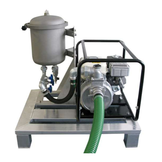
Assembly of the MOT-7 MOT-7 consists primarily of two main components: the filter unit and the pump unit. The pump unit’s task is to supply the untreated water from available water sources, to transport it to the filter unit, and to produce the needed system pressure for filtration. -
Page 8: Installation Requirements Of Components
Cleaning hose connection ½” (hose is enclosed) • Sample valve outlet ¼” Flow rates of the MOT-7 Performance MOT 7 at 4 bar Water Temperature °C The above chart shows the typical performance of the unit when operated in the standard operating conditions described in this manual. -
Page 9: Setup Procedure
Pump Honda WH 20X WH 20X – extremely sturdy The high-pressure pumps of the WH series are outfitted with the most durable and long- lasting Honda G X engines. The powerful engine and especially sturdy housing enable strong water delivery pressures with a water capacity of up to 500 liters per minute. Capacity (l/min) Capacity (m³/h) Static suction lift... -
Page 10: Setup Procedure
Filter Unit The filter unit consists of a filter housing including fittings and framing, a filter cover including a vent valve, a filter housing gasket, seven No. 5 filter elements, a cleaning hose, a measuring gauge, a handheld cleaning device. Setup Procedure Take care that the filter unit is placed in a stable position and that the location surface is dry. - Page 11 Hook up the cleaning hose to the corresponding threads. The MOT-7 is now ready for use.
-
Page 12: Brief Description Of The Handle Position Of Operational Components
Turn the main valve A counter clockwise to open • Open vent valve B just slightly • When water appears, close vent valve B (Caution: Water may begin flowing forcefully!) Now the mobile microfiltration system MOT-7 is ready for use... -
Page 13: Operation
Sampling must be performed by an experienced person according to DIN EN 25667-2 procedures. The mobile Microfiltration System MOT-7 must be set in the operational mode (see chapter 6.3). • After being prepared based on DIN EN 2557-2, the water sample can be taken... -
Page 14: Honda Handbook Reference
Maintenance and Service Honda Handbook reference Please refer to the accompanying Honda Manual regarding the correct handling of the high-pressure pump WH 20X. Both this manual and the manual from Honda must be read and completely understood. Your safety depends on it! Cleaning the filter elements •... - Page 15 Stop the Pump • Open the drain valve D and empty the filter housing • Replace the cover • The MOT-7 is ready for refilling or for storage Before storage, the filter elements must air dry for at least two days.
-
Page 16: Examining The Filter Elements
Clean the filter. Suction filter positioned Optimize the suction filter’s position. poorly (e.g. in sediment) Check the entire MOT-7 system Loss of pressure in the filter system for water leakage IMMEDIATELY replace the Filter element broken... - Page 17 Replacement Parts and Filters Product-Number Description Picture 7010719 V-Band Clamp M-MOT7; MF-7 20621 (SET) Cleaning Hose M-MOT7 complete Cleaning Brush for Katadyn Filter 20616 elements Measurement gauge for Katadyn Filter 20335 elements 1/4“ butterfly Vent Valve V4A 7010095...
- Page 18 1250 Katadyn Filter element No. 5 128031 O Ring Seal 268 x 16mm Suction Hose M-MOT7 incl. coupling to 7010633 Pump. 20615 1 Pair of Brush Segments, Nylon 1 Pair of Brush Segments, Bronze 20619 Option for difficult residue...
Need help?
Do you have a question about the MOT-7 and is the answer not in the manual?
Questions and answers