Zehnder Rittling ComfoSpot 50 Installation Instructions Manual
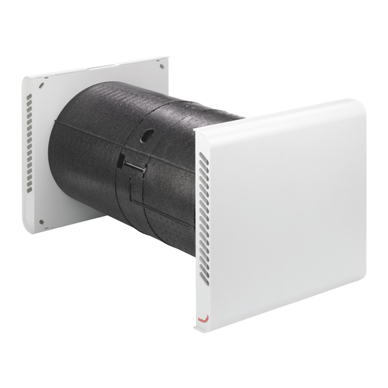
Embrasure module
Hide thumbs
Also See for ComfoSpot 50:
- Operating and installation instructions (42 pages) ,
- Manual (28 pages) ,
- Installation notes (16 pages)

Related Manuals for Zehnder Rittling ComfoSpot 50


Summary of Contents for Zehnder Rittling ComfoSpot 50
- Page 1 Design-Heizkörper Komfortable Raumlüftung Heiz- und Kühldecken-Systeme Clean Air Solutions Zehnder ComfoSpot 50 Embrasure module installation instructions...
-
Page 2: Table Of Contents
Contents Scope of delivery ........................3 Installation conditions ......................3 Installation versions ......................4 Installation position ....................... 5 Preparing for installation ....................... 6 Drilling the core hole ........................ 6 Preparatory work for direction-change adapter installation ............. 6 Preparatory work for duct adapter installation ................. 7 Installation .......................... -
Page 3: Scope Of Delivery
The embrasure module cannot be used in conjunction with the square wall mounting pipe to accommodate the ComfoSpot 50 ventilation unit. The thermal limits of -20°C and +40°C for the operation of the ventilation unit also apply to the embrasure module for air conveyance. -
Page 4: Installation Versions
Installation versions The symmetrical design of the direction-change adapter offers four options for installing the embrasure module, whereby the outdoor air (ODA) airflow is generally conducted via the upper duct connections/discharge grille and the exhaust air (EHA) airflow is conducted via the lower duct connections/discharge grille. The ... -
Page 5: Installation Position
, provided that the required installation area for ComfoSpot 50 on the inside of the outer wall is taken into account (see section 5.1 Drilling the core hole). The unit (core hole pipe axis) must be positioned so that the distance to the ceiling of the room is at least 200 mm. -
Page 6: Preparing For Installation
1. Determine the core hole position based on the relevant installation variant in section 3 Installation versions. Ensure that there is sufficient clearance around the installed ComfoSpot 50 unit and that there is enough room for maintenance work to be carried out (at least 39 cm on the left, 29 cm on the right, 70 cm at the front and 20 cm at the top –... -
Page 7: Preparatory Work For Duct Adapter Installation
2. For the remaining duct closure openings, only the protruding moulded parts (outer dimension ≙ inner dimension of duct adapter (8)) are to be cut off. Carefully cut off the protruding moulded parts in the profile groove (white dashes) so that the insulation can be laid flush with the direction-change adapter (3). 3. -
Page 8: Installation
Installation Installation steps before installing the thermal insulation composite system Installing the direction-change adapter 1. Insert the wall mounting pipe of the prepared direction-change adapter (3) into the core hole and position it horizontally in the shell wall. 2. Align the direction-change adapter (3) horizontally on the shell wall and fasten the fixing clips in place using suitable fixing material. -
Page 9: Installing The Flat Ducts/Duct Adapters/Duct Insulating Elements
Flat duct Duct adapter Shortening area: 850 mm Shortening area, recess grooves: 50 mm 1. To determine the shortening length, insert the flat duct (6) as far as it will go into the duct connection of the direction- change adapter (3) and fit the duct adapter (8) onto the flat duct (6). Make sure that the cross-section contour of the flat duct is inserted all the way into the three guides of the duct adapter (8). - Page 10 2. Align the flat duct (6) horizontally or with a minimal gradient to the duct adapter (8) and fix the duct adapter (8) in the long hole of the fixing clip (1) with suitable fixing material. 3. Press a flat duct gasket (5) blank into the duct connections of the direction-change adapter (3) and the duct adapter (8).
-
Page 11: Installation Steps While Building Up The Facade
Finally, fix the flat duct insulating elements (7) with a suitable adhesive. 7. Insert the EPP moulded parts (see section 5.2 Preparatory work for direction-change adapter installation) separated from the direction-change adapter (3) into the duct adapters (8) as blanking plugs. They will protect the airways in the embrasure module against contamination until the facade surface is finalised. -
Page 12: Facade Finish
(see section 5.2 Preparatory work for direction-change adapter installation, paragraph 2.) into the duct adapters. Facade finish The facade finish must not be applied to the front surfaces of the duct adapters. Adjust any protruding parts of the duct adapter as follows (see section 6.1.2 Adapting/shortening the flat ducts). 1. -
Page 13: Finishing The Installation
3. The condensate gutter running in the middle of the duct adapter bottom (8) is positioned just above the lower edge of the condensate outlet slot of the discharge grille (10). 4. Finally, check that the discharge grilles (10) are positioned and secured properly. 5. For further installation of the unit, refer to the ComfoSpot 50 operating instructions. - Page 14 Sales International Zehnder Group Deutschland GmbH Almweg 34 · 77933 Lahr · Germany T +49 7821 586 392 sales.international@zehndergroup.com www.international.zehnder-systems.com...
Need help?
Do you have a question about the ComfoSpot 50 and is the answer not in the manual?
Questions and answers