Table of Contents
Advertisement
Quick Links
Installation Instructions
01-2016
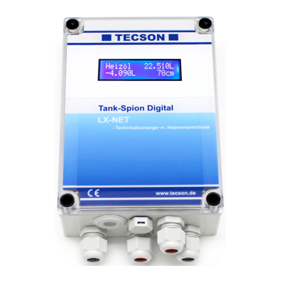
Electronic tank monitoring devices with data messaging
Tank-Spion Digital
Tank-Spion Digital
Tank-Spion Quadro LX-Q-NET
Tank-Spion Quadro LX-Q-GSM
LX-(Q)-GSM / LX-(Q)-NET
Techn. Documentation
and
Content:
ACCESSORIES
Techn. Docum. + Installation
Page:
2
3
3
4
5
6
6
8
9
9
10
11
13
15
15
16
16
P. 1
Advertisement
Table of Contents

Related Manuals for Tecson Tank-Spion Digital LX-NET


Summary of Contents for Tecson Tank-Spion Digital LX-NET
-
Page 1: Table Of Contents
Installation Instructions Techn. Documentation Electronic tank monitoring devices with data messaging Tank-Spion Digital LX-NET Tank-Spion Digital LX-GSM Tank-Spion Quadro LX-Q-NET Tank-Spion Quadro LX-Q-GSM Content: Page: GENERAL MOUNTING INSTRUCTIONS MOUNTING OF LEVEL PROBE ELECTRIC INSTALLATION CONNECTION CLAMPS DEVICE MESSAGES (SMS) DEVICE PARAMETERS (SMS) INITIAL SETUP FUNCTION CHECK MAINTANCE... -
Page 2: Lx-Net
GENERAL The electronical tank content display device of LX-Serie is to be used for monitoring of tank levels in pressureless liquid tanks. This documentation is to be used for the devices LX-GSM, LX-Q-GSM and LX-NET, LX-Q-NET. Beside the liter monitoring several other functions are available, in most cases with an extra module or adaptor. -
Page 3: Mounting Instructions
MOUNTING INSTRUCTIONS Only qualified persons are allowed to install the measuring probe and to connect the display de- vice. Follow the regulation for each liquid, especially for the risk of water pollution and for flam- mable liquids. Condition for proper operation of measuring device is a professional installation. Follow the tech- nical rules for planning, construction and operation of the entire facility. -
Page 4: Electric Installation
Probe box : To be used - outdoors - in manhole pit (buried tanks) - in damp locations. The probe box must be wa- tertight and ventilated (for pressure balance of the hydrostatic level probe). ELECTRIC INSTALLATION Interconnection of measuring probe to display device Probe supply: Low-voltage DC Connection: Connect the 2-wire probe cable as follows:... -
Page 5: Connection Clamps
CONNECTION CLAMPS If LX-GSM and LX-NET Relay connection: The LX-GSM and LX-NET devices do have a double output relay. By this relay two separate elec- tric circuits can be switched simultaneously, e.g. a signalling device on/off and an electric valve off/on too. Under initial conditions the relay contacts 7-8 are closed and relay contacts 9-10 are opened. -
Page 6: Device Messages (Sms)
For LX-Q-GSM : pushbuttons SIM card Measuring probes 1 ( to 4 ) 230 V supply For LX-GSM / LX-Q-GSM : DEVICE MESSAGES (SMS) See additional documention: “ Messages, Commands a. Parameters ati GSM-Messenger, LX-GSM, LX-Q-GSM “ If the device will be linked to the www.oilview.de system for remote management then these communication details via mobile phone are not relevant. - Page 7 For LX-NET / LX-Q-NET : LX-NET connection clamps: Probe | Serial-Link-In | Digital-In (Alarm) Pushbuttons Relay conttact pairs 230V supply LX-Q-NET connection clamps: Alarm input | Pushbuttons Measuring probes 1 ( to 4 ) 230V supply 01-2016 LX-(Q)-GSM / LX-(Q)-NET Techn.
-
Page 8: Initial Setup
INITIAL SETUP The initial setup is carried out after completed mounting. Determine the tank data and enter them into the mode: You find 3 push buttons (blue) on the PCB positioned between the connection clamps. Press ENTER => Device enters the setup mode Displayed step „1. -
Page 9: Function Check
FUNCTION CHECK After fueling or once a year please check if the displayed liters are correct. MAINTANCE It is recommended to check once year if the displayed liters are correct. For a simple check lift the level probe by the cable so that the probe is above the liquid level. -
Page 10: Network Connection
For LX-NET / LX-Q-NET : NETWORK CONNECTION Netzwork connection: The LX-(Q)-NET device has a directly connectivety to LAN/Ethernet network with 10 / 100 Mbit TCP/IP protocol. Inside the housing you find the RJ45 jack for connecting a CAT-5 network cable. The plug of the network cable has to be pushed through the inlet at bottom side of the housing. -
Page 11: Browser Access
BROWSER ACCESS Show content in browser: Entering the IP address in your browsers address line the device will be called: LX-(Q)-GSM / LX-(Q)-NET Techn. Docum. + Installation P. 11 01-2016... - Page 12 Parameter setup via Browser: Clicking the ’CONFIG’ button opens a next page in tzhe browser. Here you can setup serveral parameters for the device. Password: The inital passwort for config access at the device is: tank The password is changeable here. It is recommended to store an individual device password.
-
Page 13: Error Codes
ERROR CODES Error code Meaning Error E 1 Invalid value setup. Error E 2 Measuring value of the probe is too low ! If current is less than 3.5 mA => Probe error. Measuring value too high for probe offset/zero calibration. The probe must not be Error E 3 plunged! A probe’s current above 4.5 mA is invalid as zero point. - Page 14 LX-(Q)-NET: Error-Messages at network communication Error N1 No network communication. A problem with the internal network module. The device automatically executes a ’Reset’ for the internal network module and retrys initial communications. Try disconnection of network plug, wait… and remount the network plug. Error N2 Error at the network communication.
-
Page 15: Technical Data
TECHNICAL DATA Display device Type AC : 230 V 50 Hz Supply voltage: Type DC : 12V or 24V version Power consumption: <= 4 VA 4 - 20mA ; U = 20V Measuring input: Resolution 10 Bit Accuracy: ± 1 % Output via plug-in adaptor: ▪... -
Page 16: Labeling
EN 61010-1 (2011) EMV examination: EN 61000-6-2 (2006) and EN 61000-6-4 (2011) For LX-(Q)-GSM: Radio examination EN 301 511 (2003) For Conformity Declaration refer to ‘www.tecson.de‘ at menu item ‘Documentation -> CE Declaration‘. Manufacturer: TECSON GmbH & Co KG Wulfsfelder Weg 2a...
Need help?
Do you have a question about the Tank-Spion Digital LX-NET and is the answer not in the manual?
Questions and answers