Table of Contents
Advertisement
Advertisement
Table of Contents

Related Manuals for Asus PRIME Z390-P


Summary of Contents for Asus PRIME Z390-P
- Page 1 PRIME Z390-P...
- Page 2 Product warranty or service will not be extended if: (1) the product is repaired, modified or altered, unless such repair, modification of alteration is authorized in writing by ASUS; or (2) the serial number of the product is defaced or missing.
-
Page 3: Table Of Contents
Contents Safety information ..................iv About this guide ..................iv Package contents ..................vi PRIME Z390-P specifications summary ............ vi Chapter 1 Product introduction Before you proceed ..............1-1 Motherboard overview ..............1-1 Central Processing Unit (CPU) ........... 1-3 System memory ................1-7 Expansion slots ................ -
Page 4: Safety Information
Safety information Electrical safety • To prevent electrical shock hazard, disconnect the power cable from the electrical outlet before relocating the system. • When adding or removing devices to or from the system, ensure that the power cables for the devices are unplugged before the signal cables are connected. If possible, disconnect all power cables from the existing system before you add a device. -
Page 5: Conventions Used In This Guide
Refer to the following sources for additional information and for product and software updates. ASUS websites The ASUS website provides updated information on ASUS hardware and software products. Refer to the ASUS contact information. Optional documentation Your product package may include optional documentation, such as warranty flyers, that may have been added by your dealer. -
Page 6: Package Contents
Extreme Memory Profile (XMP) * The maximum memory frequency supported varies by processor. ** Refer to www.asus.com for the latest Memory QVL (Qualified Vendors List). 1 x PCI Express 3.0/2.0 x16 slot (support x16, x8+x4+x4*) 1 x PCI Express 3.0/2.0 x16 slot (max. at x4 mode, compatible with PCIe x1, x2 and x4 devices) 4 x PCI Express 3.0/2.0 x1 slots... - Page 7 - 3 x USB 2.0/1.1 ports (3 ports @mid-board) ASUS 5X PROTECTION III - ASUS SafeSlot Core: Fortified PCIe with solid soldering - ASUS LANGuard: Protects against LAN surges, lightning strikes and static- electricity discharges - ASUS Overvoltage Protection: World-class circuit-protecting power design...
- Page 8 - ASUS Q-DIMM - ASUS Q-Slot Quiet Thermal Design ASUS quiet thermal - ASUS ASUS Fan Xpert 4 solution - Stylish Fanless Design: PCH Heat-sink & 2*MOS Heat-sink Precision Tweaker 2: - vCore: Adjustable CPU Core voltage at 0.005V increment - iGPU: Adjustable CPU Graphics voltage at 0.005V increment - vCCIO: Adjustable Analog and Digital I/O voltage at 0.005V increment...
- Page 9 CPU and chassis fans installed and changes the control mode automatically. 128 Mb Flash ROM, UEFI AMI BIOS, PnP, SM BIOS 3.1, ACPI 6.1, Multi- language BIOS, ASUS EZ Flash 3, CrashFree BIOS 3, F11 EZ Tuning Wizard, BIOS features...
-
Page 11: Before You Proceed
When installing the motherboard, place it into the chassis in the correct orientation. The edge with external ports goes to the rear part of the chassis as indicated in the image. 1.2.2 Screw holes Place six screws into the holes indicated by circles to secure the motherboard to the chassis. Do not overtighten the screws! Doing so can damage the motherboard. ASUS PRIME Z390-P... -
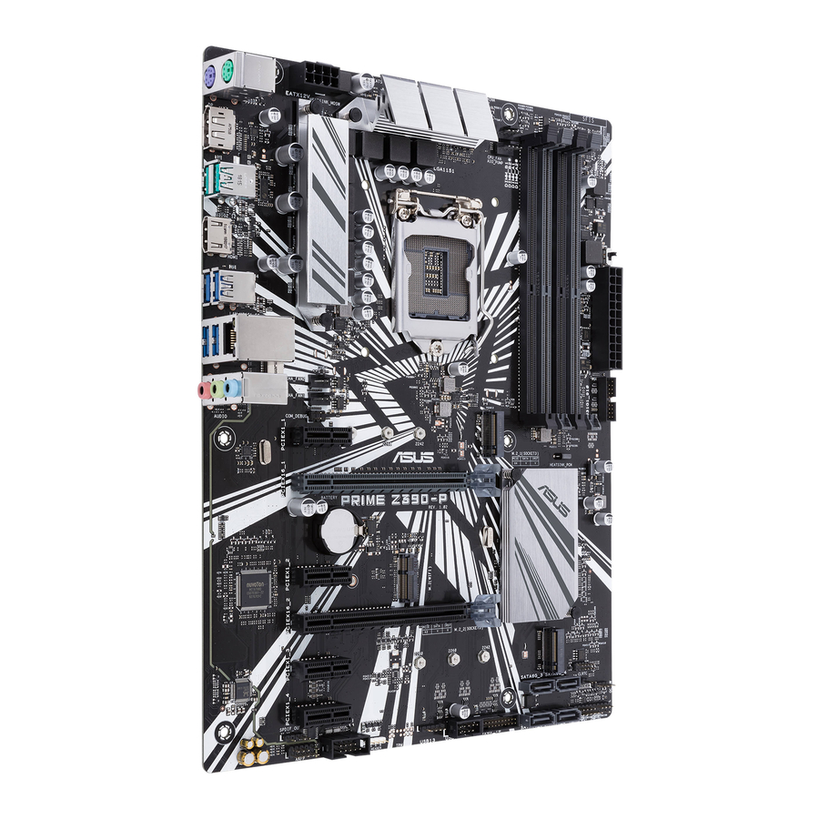
Page 12: Motherboard Layout
Place this side towards the rear of the chassis PRIME Z390-P 1.2.3 Motherboard layout 23.4cm(9.2in) KBMS EATX12V DIGI+ CPU_FAN AIO_PUMP U31G2_12 MemOK!_II Mem_LED HDMI LGA1151 U31G1_34 LAN_U31G1_56 CHA_FAN2 AUDIO CHA_FAN1 U31G1_910 PCIEX1_1 2280 2260 2242 PCIE SATA IRST PRIME Z390-P Realtek ®... -
Page 13: Table Of Contents
Z390 SATA 6.0 Gb/s connectors (7-pin SATA6G_1-4) 1-19 ® 13. USB 2.0 connectors (10-1 pin USB1112, USB13) 1-16 14. RGB header (4-pin RGB_HEADER) 1-11 15. Serial port connectors (10-1 pin COM) 1-15 16. Digital audio connector (4-1 pin SPDIF_OUT) 1-17 17. Front panel audio connector (10-1 pin AAFP) 1-16 Central Processing Unit (CPU) This motherboard comes with a surface mount LGA1151 socket designed for Intel Core™ ® 9000 series, 8 Generation Core™ i7/ i5/ i3, Pentium and Celeron processors ® ® PRIME Z390-P CPU socket LGA1151 Unplug all power cables before installing the CPU. ASUS PRIME Z390-P... -
Page 14: Installing The Cpu
• Ensure that you install the correct CPU designed for the LGA1151 socket only. DO NOT install a CPU designed for LGA1150, LGA1155 and LGA1156 sockets on the LGA1151 socket. • Upon purchase of the motherboard, ensure that the PnP cap is on the socket and the socket contacts are not bent. Contact your retailer immediately if the PnP cap is missing, or if you see any damage to the PnP cap/socket contacts/motherboard components. • Keep the cap after installing the motherboard. ASUS will process Return Merchandise Authorization (RMA) requests only if the motherboard comes with the cap on the LGA1151 socket. • The product warranty does not cover damage to the socket contacts resulting from incorrect CPU installation/removal, or misplacement/loss/incorrect removal of the PnP cap. 1.3.1 Installing the CPU Chapter 1: Product introduction... -
Page 15: Cpu Heatsink And Fan Assembly Installation
1.3.2 CPU heatsink and fan assembly installation Apply the Thermal Interface Material to the CPU heatsink and CPU before you install the heatsink and fan if necessary. ASUS PRIME Z390-P... - Page 16 To install the CPU heatsink and fan assembly To uninstall the CPU heatsink and fan assembly Chapter 1: Product introduction...
-
Page 17: System Memory
System memory 1.4.1 Overview This motherboard comes with four Double Data Rate 4 (DDR4) Dual Inline Memory Module (DIMM) sockets. A DDR4 module is notched differently from a DDR, DDR2, or DDR3 module. DO NOT install a DDR, DDR2, or DDR3 memory module to the DDR4 slot. According to Intel CPU spec, DIMM voltage below 1.35 V is recommended to protect the ® CPU. PRIME Z390-P 288-pin DDR4 DIMM sockets 1.4.2 Memory configurations You may install 2 GB, 4 GB, 8 GB, and 16 GB unbuffered non-ECC DDR4 DIMMs into the DIMM sockets. You can refer to the recommended memory population below. Recommended memory configurations • You may install varying memory sizes in Channel A and Channel B. The system maps the total size of the lower-sized channel for the dual-channel configuration. Any excess memory from the higher-sized channel is then mapped for single-channel operation. • According to Intel CPU spec, DIMM voltage below 1.35V is recommended to protect ® the CPU. • When using one DIMM, install it into slot A2 for better memory compatibility and performance ASUS PRIME Z390-P... -
Page 18: Installing A Dimm
• The default memory operation frequency is dependent on its Serial Presence Detect (SPD), which is the standard way of accessing information from a memory module. Under the default state, some memory modules for overclocking may operate at a lower frequency than the vendor-marked value. To operate at the vendor-marked or at a higher frequency, refer to section 2.5 Ai Tweaker menu for manual memory frequency adjustment. • Always install the DIMMS with the same CAS Latency. For an optimum compatibility, we recommend that you install memory modules of the same version or data code (D/C) from the same vendor. Check with the vendor to get the correct memory modules. • For system stability, use a more efficient memory cooling system to support a full memory load (4 DIMMs) or overclocking condition. Visit the ASUS website at www.asus.com for the latest QVL. 1.4.3 Installing a DIMM To remove a DIMM Chapter 1: Product introduction... -
Page 19: Expansion Slots
Align the card connector with the slot and press firmly until the card is completely seated on the slot. Secure the card to the chassis with the screw you removed earlier. Replace the system cover. 1.5.2 Configuring an expansion card After installing the expansion card, configure it by adjusting the software settings. Turn on the system and change the necessary BIOS settings, if any. See Chapter 2 for information on BIOS setup. Assign an IRQ to the card. Install the software drivers for the expansion card. When using PCI cards on shared slots, ensure that the drivers support “Share IRQ” or that the cards do not need IRQ assignments. Otherwise, conflicts will arise between the two PCI groups, making the system unstable and the card inoperable. 1.5.3 PCI Express 3.0 x1 slots This motherboard supports PCI Express 3.0 x1 network cards, SCSI cards, and other cards that comply with the PCI Express specifications. 1.5.4 PCI Express 3.0 x16 slots This motherboard has two PCI Express 3.0 x16 slots (x16 + x4 mode) that support PCI Express 3.0 x16 graphic cards complying with the PCI Express specifications. ASUS PRIME Z390-P... -
Page 20: Headers
PCIe 3.0 x16_1 (gray) PCIe 3.0 x16_2 (black) 3 Intel SSDs on CPU support x8+x4+x4 ® • Hyper M.2 X16 card is purchased separately. • Enable the Hyper M.2 X16 card under BIOS settings. Headers Clear RTC RAM (2-pin CLRTC) This header allows you to clear the Real Time Clock (RTC) RAM in CMOS. You can clear the CMOS memory of date, time, and system setup parameters by erasing the CMOS RTC RAM data. The onboard button cell battery powers the RAM data in CMOS, which include system setup information such as system passwords. CLRTC PIN 1 PRIME Z390-P Clear RTC RAM 1-10 Chapter 1: Product introduction... -
Page 21: Rgb Header (4-Pin Rgb_Header)
Hold down the <Del> key during the boot process and enter BIOS setup to re- enter data. If the steps above do not help, remove the onboard battery and short the two pins again to clear the CMOS RTC RAM data. After clearing the CMOS, reinstall the battery. RGB header (4-pin RGB_HEADER) This header is for RGB LED strips. The RGB header supports 5050 RGB multi-color LED strips (12V/G/R/B), with a maximum power rating of 3A (12V), and no longer than 3 m. Before you install or remove any component, ensure that the ATX power supply is switched off or the power cord is detached from the power supply. Failure to do so may cause severe damage to the motherboard, peripherals, or components. • Actual lighting and color will vary with LED strip. • If your LED strip does not light up, check if the RGB LED extension cable and the RGB LED strip is connected in the correct orientation, and the 12V connector is aligned with the 12V header on the motherboard. • The LED strip will only light up when the system is operating. • The LED strips are purchased separately. RGB_HEADER PIN 1 +12V G R B PRIME Z390-P RGB_HEADER connector ASUS PRIME Z390-P 1-11... -
Page 22: Onboard Switches
Onboard switches Onboard switches allow you to fine-tune performance when working on a bare or open- case system. This is ideal for overclockers and gamers who continually change settings to enhance system performance. MemOK! II switch (MemOK!_II) Installing DIMMs that are not compatible with the motherboard may cause system boot failure. The switch is enabled by default, allowing memory re-training when the motherboard is unresponsive due to memory problems. The Mem_LED will light up while re-training, and turn off when the re-training is complete. MemOK!_II PRIME Z390-P MemOK! switch • Refer to section 1.1.8 Onboard LEDs for the exact location of the Mem_LED. • The DRAM LED also lights up when the DIMM is not properly installed. Turn off the system and reinstall the DIMM before using the MemOK! II function. • The MemOK! II switch does not function under Windows OS environment. ® • During the tuning process, the system loads and tests pretest profiles. It takes about 30 seconds for the system to test one set of profiles. If the test fails, the system reboots and tests the next set of profiles. The system will reboot multiple times when training, once the system has completed the training process the Mem_LED will turn off, please refrain from doing anything before the Mem_LED turns off. • Due to memory tuning requirement, the system automatically reboots when each profile is tested. If the installed DIMMs still fail to boot after the whole tuning process,... -
Page 23: Connectors
Onboard LEDs Memory LED (Mem_LED) The Mem_LED will light up and remain lit while the MemOK! II function is in use. When the re-training is complete, the Mem_LED will turn off. Mem_LED PRIME Z390-P MemOK!_LED Connectors 1.7.1 Rear panel connectors PS/2 mouse port (green). This port is for a PS/2 mouse. LAN (RJ-45) port. This port allows Gigabit connection to a Local Area Network (LAN) through a network hub. ASUS PRIME Z390-P 1-13... - Page 24 LAN port LED indications Activity/Link LED Speed LED Speed Activity Link Status Description Status Description No link 10Mbps connection Orange Linked ORANGE 100Mbps connection Orange Data activity GREEN 1Gbps connection (Blinking) LAN port Orange Ready to (Blinking then wake up from steady) S5 mode Line In port (light blue). This port connects to the tape, CD, DVD player, or other audio sources.
-
Page 25: Serial Port Connectors (10-1 Pin Com)
USB 3.1 Gen 2 / Gen 1 devices can only be used for data storage. • Due to the design of the Intel 300 series chipset, all USB devices connected to the ® USB 2.0 and USB 3.1 Gen 2 / Gen 1 ports are controlled by the xHCI controller. Some legacy USB devices must update their firmware for better compatibility. • We strongly recommend that you connect USB 3.1 Gen 2 devices to USB 3.1 Gen 2 ports for faster and better performance from your USB 3.1 Gen 2 devices. DisplayPorts. These ports are for DisplayPort-compatible devices. PS/2 keyboard port (purple). This port is for a PS/2 keyboard. 1.7.2 Internal connectors Serial port connector (10-1 pin COM) This connector is for a serial (COM) port. Connect the serial port module cable to this connector, then install the module to a slot opening at the back of the system chassis. PIN 1 PRIME Z390-P Serial port (COM) connector The COM module is purchased separately. ASUS PRIME Z390-P 1-15... -
Page 26: Front Panel Audio Connector (10-1 Pin Aafp)
Front panel audio connector (10-1 pin AAFP) This connector is for a chassis-mounted front panel audio I/O module that supports HD Audio standard. Connect one end of the front panel audio I/O module cable to this connector. AAFP HD-audio-compliant pin definition PRIME Z390-P Front panel audio connector We recommend that you connect a high-definition front panel audio module to this connector to avail of the motherboard’s high-definition audio capability. USB 2.0 connectors (10-1 pin USB1112, 4 pin USB13) These connectors are for USB 2.0 ports. Connect the USB module cable to any of these connectors, then install the module to a slot opening at the back of the system chassis. These USB connectors comply with USB 2.0 specifications and supports up to 480Mbps connection speed. USB1112 USB13 PIN 1 PIN 1 PRIME Z390-P USB2.0 connectors... -
Page 27: Digital Audio Connector (4-1 Pin Spdif_Out)
IntA_P2_SSTX- IntA_P1_SSTX+ IntA_P2_SSTX+ IntA_P1_D- IntA_P2_D- IntA_P1_D+ IntA_P2_D+ U31G1_78 PIN 1 PRIME Z390-P USB3.0 Front panel connectors The USB 3.1 Gen 1 module is purchased separately. Digital audio connector (4-1 pin SPDIF_OUT) This connector is for an additional Sony/Philips Digital Interface (S/PDIF) port. Connect the S/PDIF Out module cable to this connector, then install the module to a slot opening at the back of the system chassis. SPDIF_OUT PRIME Z390-P Digital audio connector The S/PDIF module is purchased separately. - Page 28 Power OK -5 Volts PIN 1 +5 Volts +5 Volts PSON# +3 Volts -12 Volts +3 Volts +3 Volts PIN 1 PRIME Z390-P ATX power connectors • For a fully configured system, we recommend that you use a power supply unit (PSU) that complies with ATX 12 V Specification 2.0 (or later version) and provides a minimum power of 350 W. • DO NOT forget to connect the 4-pin/8-pin ATX +12V power plug. Otherwise, the system will not boot up. • We recommend that you use a PSU with higher power output when configuring a system with more power-consuming devices or when you intend to install additional devices. The system may become unstable or may not boot up if the power is...
-
Page 29: Intel ® Z390 Sata 6.0 Gb/S Connectors (7-Pin Sata6G_1-4)
See section 2.6.5 PCH Storage Configuration for details. M.2 WiFi This socket allows you to install an M.2 (WIFI) module. M.2(WIFI) PIN74 PIN 1 S_USB_PP10_R S_USB_PN10_R M2_ISOLATE#_R BT_ISOLATE#_R S_PLTRST# X_WIFI_TXP S_SUSCLK X_WIFI_TXN X_WIFI_RXP CL_CLK X_WIFI_RXN CL_DATA CL_RST# C_PCIE_WIFI 2230 C_PCIE_WIFI# L1_WIFI_CLKREQ# S_WAKE# PIN2 PIN 75 PRIME Z390-P M.2 WIFI socket The M.2 (NGFF) SSD module is purchased separately. ASUS PRIME Z390-P 1-19... -
Page 30: M.2 Socket 3 [M.2_1(Socket 3)]
M.2 socket 3 [M.2_1(Socket 3); M.2_2(Socket 3)] These sockets allow you to install M.2 (NGFF) SSD modules. M.2_1(SOCKET3) 2280 2260 2242 M.2_2(SOCKET3) 2280 2260 2242 PRIME Z390-P M.2(SOCKET3)s • These M.2 sockets support M Key and type 2242/2260/2280 storage devices. • When using Intel Desktop Responsiveness technologies with PCIe/SATA M.2 device, ® ensure to set up the Windows UEFI operating system under RAID mode. ® • These M.2 sockets support data transfer speed up to 32Gb/s. • W hen a device in SATA mode is installed on the M.2_1 socket, SATA6G_2 port cannot be used. The M.2 (NGFF) SSD module is purchased separately. 1-20 Chapter 1: Product introduction... -
Page 31: Cpu, Aio Pump, And Chassis Fan Connectors (4-Pin Cpu_Fan, 4-Pin Aio_
CPU, AIO pump, and chassis fan connectors (4-pin CPU_FAN, 4-pin AIO_PUMP, and 4-pin CHA_FAN1/2) Connect the fan cables to the fan connectors on the motherboard, ensuring that the black wire of each cable matches the ground pin of the connector CPU_FAN AIO_PUMP CHA_FAN2 CHA_FAN1 PRIME Z390-P Fan connectors • Do not forget to connect the fan cables to the fan connectors. Insufficient air flow inside the system may damage the motherboard components. These are not jumpers! Do not place jumper caps on the fan connectors! • Ensure that the CPU fan cable is securely installed to the CPU fan connector. •... -
Page 32: System Panel Connector (20-5 Pin Panel)
System panel connector (20-5 pin PANEL) This connector supports several chassis-mounted functions. PLED PWRSW SPEAKER PANEL PIN 1 HDD_LED RESET PLED PRIME Z390-P System panel connector • System power LED (4-pin +PWR_LED-) This 4-pin connector is for the system power LED. Connect the chassis power LED cable to this connector. The system power LED lights up when you turn on the system power, and blinks when the system is in sleep mode. • Hard disk drive activity LED (2-pin +HDD_LED-) This 2-pin connector is for the HDD Activity LED. Connect the HDD Activity LED cable to this connector. The HDD LED lights up or flashes when data is read from or written to the HDD. • System warning speaker (4-pin SPEAKER) This 4-pin connector is for the chassis-mounted system warning speaker. The speaker allows you to hear system beeps and warnings. -
Page 33: Software Support
To run the Support DVD Place the Support DVD into the optical drive. If Autorun is enabled in your computer, the DVD automatically displays the lists of the unique features of your ASUS motherboard. Click the Driver, Utilities, Manual, or Special tabs to display their respective menus. The following screen is for reference only. Click to install Select an item/ subitem that you Click a tab to want to install display Support DVD information If Autorun is NOT enabled in your computer, browse the contents of the Support DVD to locate the file Setup.exe in the root folder. Double-click the Setup.exe to run the DVD. ASUS PRIME Z390-P 1-23... - Page 34 1-24 Chapter 1: Product introduction...
-
Page 35: Managing And Updating Your Bios
Save a copy of the original motherboard BIOS file to a USB flash disk in case you need to restore the BIOS in the future. Copy the original motherboard BIOS using the ASUS Update utility. (BIOS version template: PRIME Z390-P 0313 version) 2.1.1... -
Page 36: Asus Ez Flash
2.1.2 ASUS EZ Flash 3 The ASUS EZ Flash 3 feature allows you to update the BIOS without using an OS-based utility. • Ensure to load the BIOS default settings to ensure system compatibility and stability. Select the Load Optimized Defaults item under the Exit menu. See section 2.10 Exit Menu for details. -
Page 37: Asus Crashfree Bios 3 Utility
2.1.3 ASUS CrashFree BIOS 3 utility The ASUS CrashFree BIOS 3 is an auto recovery tool that allows you to restore the BIOS file when it fails or gets corrupted during the updating process. You can restore a corrupted BIOS file using the motherboard support DVD or a USB flash drive that contains the updated BIOS file. - Page 38 ENTER to select boot device ESC to boot using defaults P2: ST3808110AS (76319MB) aigo miniking (250MB) UEFI: (FAT) ASUS DRW-2014L1T(4458MB) P1: ASUS DRW-2014L1T(4458MB) UEFI: (FAT) aigo miniking (250MB) Enter Setup When the booting message appears, press <Enter> within five (5) seconds to enter FreeDOS prompt.
- Page 39 DO NOT shut down or reset the system while updating the BIOS to prevent system boot failaure. Ensure to load the BIOS default settings to ensure system compatibility and stability. Select the Load Optimized Defaults item under the Exit BIOS menu. See section 2.10 Exit Menu for details. ASUS PRIME Z390-P...
-
Page 40: Bios Setup Program
The BIOS setup screens shown in this section are for reference purposes only, and may not exactly match what you see on your screen. • Visit the ASUS website at www.asus.com to download the latest BIOS file for this motherboard. •... - Page 41 Click the button to manually Saves the changes tune the fans and resets the Selects the boot Loads optimized system device priority default settings The boot device options vary depending on the devices you installed to the system. ASUS PRIME Z390-P...
-
Page 42: Advanced Mode
2.2.2 Advanced Mode The Advanced Mode provides advanced options for experienced end-users to configure the BIOS settings. The figure below shows an example of the Advanced Mode. Refer to the following sections for the detailed configurations. To access the EZ Mode, click EzMode(F7) or press <F7>. EZ Tuning MyFavorite Q-Fan control... -
Page 43: Menu Bar
This button above the menu bar allows you to view and tweak the overclocking* settings of your system. It also allows you to change the motherboard’s SATA mode from AHCI to RAID mode. Refer to section 2.2.4 EZ Tuning Wizard for more information. ASUS PRIME Z390-P... -
Page 44: Hot Keys
Hot keys This button above the menu bar contains the navigation keys for the BIOS setup program. Use the navigation keys to select items in the menu and change the settings. Scroll bar A scroll bar appears on the right side of a menu screen when there are items that do not fit on the screen. -
Page 45: Qfan Control
CPU and chassis fans. Click to select a fan to be configured Click to apply Select a profile to apply the fan setting to your fans Click to undo Click to the changes go back to main menu ASUS PRIME Z390-P 2-11... - Page 46 Configuring fans manually Select Manual from the list of profiles to manually configure your fans’ operating speed. Click to manually Speed points configure your fans To configure your fans: Select the fan that you want to configure and to view its current status. Click and drag the speed points to adjust the fans’...
-
Page 47: Ez Tuning Wizard
Select the CPU fan type (Box cooler, Tower cooler, or Water cooler) that you installed then click Next. If you are not sure of the CPU fan type, click I’m not sure. The system automatically detects the CPU fan type. Click Next then click Yes to confirm auto-tuning. ASUS PRIME Z390-P 2-13... -
Page 48: Creating Raid
Creating RAID To create RAID: Press <F11> on your keyboard or click from the BIOS screen to open EZ Tuning Wizard screen. Click RAID then click Yes to enable RAID. • Ensure that your HDDs have no existing RAID volumes. •... - Page 49 For Easy Backup, select from Super Speed (RAID0) or Super Speed (RAID5) then click Next. After selecting the type of RAID, click Yes to continue the RAID setup. After the RAID setup is done, click Yes to exit the setup then click OK to reset your system. ASUS PRIME Z390-P 2-15...
-
Page 50: My Favorites
My Favorites MyFavorites is your personal space where you can easily save and access your favorite BIOS items. 2-16 Chapter 2: Getting started... - Page 51 You cannot add user-managed items such as language and boot order to My Favorites. Click Exit (ESC) or press <esc> key to close Setup Tree Map screen. Go to My Favorites menu to view the saved BIOS items. ASUS PRIME Z390-P 2-17...
-
Page 52: Main Menu
Main menu The Main menu screen appears when you enter the Advanced Mode of the BIOS Setup program. The Main menu provides you an overview of the basic system information, and allows you to set the system date, time, language, and security settings. 2.4.1 Language [English] Allows you to choose the BIOS language version from the options. -
Page 53: Administrator Password
To clear the user password, follow the same steps as in changing a user password, but press <Enter> when prompted to create/confirm the password. After you clear the password, the User Password item on top of the screen shows Not Installed. ASUS PRIME Z390-P 2-19... -
Page 54: Ai Tweaker Menu
Ai Tweaker menu The Ai Tweaker menu items allow you to configure overclocking-related items. Be cautious when changing the settings of the Ai Tweaker menu items. Incorrect field values can cause the system to malfunction. The configuration options for this section vary depending on the CPU and DIMM model you installed on the motherboard. - Page 55 [Auto] [Enabled] [Disabled]. 2.5.2 ASUS MultiCore Enhancement [Auto] [Auto] This item allows you to maximize the oveclocking performance optimized by ASUS core ratio settings. [Disabled] This item allows you to set to default core ratio settings. 2.5.3 SVID Behavior [Auto] This item allows you to program the CPU’s SVID behavior base on CPU’s quality.
-
Page 56: Dram Timing Control
Selecting a very high memory frequency may cause the system to become unstable! If this happens, revert to the default setting. 2.5.7 OC Tuner [Keep Current Settings]* This item allows you to automatically overclock the CPU and DRAM frequencies and voltage for an enhanced system performance. - Page 57 CPU Graphics VRM Switching Frequency [Auto] The switching frequency will affect the GT transient response speed and the component thermal production. Select [Manual] to configure a higher frequency for a quicker transient response speed. Configuration options: [Auto] [Manual] ASUS PRIME Z390-P 2-23...
- Page 58 DO NOT remove the thermal module. The thermal conditions should be monitored. The following item appears only when you set the GT VRM Switching Frequency to [Manual]. Fixed VCCGT Switching Frequency (KHz) [250] This item allows you to set a higher frequency for a quicker transient response speed. Use the <+>...
- Page 59 CPU Core/Cache Current Limit Max. [Auto] This item allows you to configure a higher current limit to prevent a frequency or power throttling when overclocking. Use the <+> and <-> keys to adjust the value. Configuration options: [Auto] [0.00] - [255.50] ASUS PRIME Z390-P 2-25...
- Page 60 2.5.14 CPU Graphics Current Limit [Auto] This item allows you to configure a higher current limit to prevent a frequency or power throttling when overclocking. Use the <+> and <-> keys to adjust the value. Configuration options: [Auto] [0.00] - [255.50] 2.5.15 Min.
- Page 61 DRAM REF Voltage Control [Auto] The subitems in this menu allows you to set the DRAM reference voltage on the control lines from the memory bus. You can use the <+> or <-> keys to adjust the value. ASUS PRIME Z390-P 2-27...
-
Page 62: Advanced Menu
Advanced menu The Advanced menu items allow you to change the settings for the CPU and other system devices. Be cautious when changing the settings of the Advanced menu items. Incorrect field values can cause the system to malfunction. 2.6.1 Platform Misc Configuration The items in this menu allow you to configure the platform-related features. -
Page 63: Cpu Configuration
ASPM to take effect. Configuration options: [Disabled] [L1] PEG - ASPM [Disabled] This item allows you to select the ASPM state for energy-saving conditions, or use the ASUS optimized energy saving profile. Configuration options: [Disabled] [Auto] [ASPM L0s] [ASPM L1] [ASPM L0sL1] 2.6.2... - Page 64 Hardware Prefetcher [Enabled] This item allows the CPU to prefetch commands and data in the L2 cache, reduces the DRAM loading time and improves the system performance. Configuration options: [Disabled] [Enabled] Adjacent Cache Line Prefetch [Enabled] This item allows the mid level cache (L2) to prefetch adjacent cache lines, reducing the DRAM loading time and improves the system performance.
-
Page 65: Memory Configuration
Allows you to enable or disable the 4G decoding for 64-bit devices when the system supports the 64-bit PCI decoding. Configuration options: [Enabled] [Disabled] Memory Configuration Allows you to configure the memory configuration parameters. Memory Remap [Enabled] Allows you to enable or disable memory remap above 4GB. Configuration options: [Enabled] [Disabled] ASUS PRIME Z390-P 2-31... -
Page 66: Graphics Configuration
Graphics Configuration Allows you to select a primary display from CPU, PCIE and PCI graphical devices. Primary Display [Auto] Allows you to select the primary display from CPU, PCIE and PCI graphics devices. Configuration options: [Auto] [CPU Graphics] [PCIE] iGPU Multi-Monitor [Disabled] This item allows you to empower both integrated and discrete graphics devices for the multi-monitor output. -
Page 67: Onboard Devices Configuration
2.6.7 Onboard Devices Configuration Hyper M.2X16 [Enabled][Disabled] [Disabled] Only one SSD installed onto the Hyper M.2 X16 card can be detected. [Enabled] Two or three SSDs installed onto the Hyper M.2 X16 card can be detected. ASUS PRIME Z390-P 2-33... -
Page 68: Serial Port Configuration
The number of SSDs that can be detected varies with the configurations of the PCIe X16 slots. HD Audio [Enabled] [Enabled] Enables the HD Audio Device. [Disabled] Disables the HD Audio Device. The following two items appear only when you set the HD Audio Controller item to [Enabled]. -
Page 69: Apm Configuration
This item allows you to enable or disable the RTC (Real-Time Clock) to generate a wake event and configure the RTC alarm date. When enabled, you can set the days, hours, minutes, or seconds to schedule an RTC alarm date. Configuration options: [Disabled] [Enabled] ASUS PRIME Z390-P 2-35... -
Page 70: Pci Subsystem Settings
2.6.9 PCI Subsystem Settings SR-IOV Support [Disabled] This item allows you to enable or disable the Single Root IO Virtualization support if your system has SR-IOV capable PCIe devices. Configuration options: [Disabled] [Enabled] 2.6.10 USB Configuration The items in this menu allow you to change the USB-related features. The USB Devices item shows the auto-detected values. -
Page 71: Monitor Menu
The onboard hardware monitor automatically detects and displays the CPU, chassis and AIO PUMP fan speeds in rotations per minute (RPM). If the fan is not connected to the motherboard, the field shows N/A. Select [Ignore] if you do not wish to display the detected speed. ASUS PRIME Z390-P 2-37... - Page 72 2.7.3 CPU Core Voltage, 3.3V Voltage, 5V Voltage, 12V Voltage The onboard hardware monitor automatically detects the voltage output through the onboard voltage regulators. Select [Ignore] if you do not want to detect this item. 2.7.4 Q-Fan Configuration The subitems in this menu allows you to configure the Q-Fan features. Q-Fan Tuning Click [OK] button to detect the lowest speed and configure the minimum duty circle for each fan.
- Page 73 [204 sec] Chassis Fan 1/2 Speed Low Limit [200 RPM] This item allows you to disable or set the chassis fan warning speed. Configuration options: [Ignore] [200RPM] [300 RPM] [400 RPM] [500 RPM] [600 RPM] ASUS PRIME Z390-P 2-39...
- Page 74 Chassis Fan 1/2 Profile [Standard] This item allows you to set the appropriate performance level of the chassis fan. [Standard] Sets to [Standard] to make the chassis fan automatically adjust depending on the chassis temperature. [Silent] Sets to [Silent] to minimize the fan speed for quiet chassis fan operation.
-
Page 75: Boot Menu
60% to 100%. When the CPU temperature is under the lower limit, the AIO PUMP fan operates at the minimum duty cycle. Boot menu The Boot menu items allow you to change the system boot options. Scroll down to display the other BIOS items. ASUS PRIME Z390-P 2-41... -
Page 76: Boot Configuration
2.8.1 Boot Configuration Fast Boot [Enabled] [Enabled] Select to accelerate the boot speed. [Disabled] Select to go back to normal boot speed. The following item appears only when you set Fast Boot to [Enabled]. Next Boot after AC Power Loss [Normal Boot] [Normal Boot] Returns to normal boot on the next boot after AC power loss. -
Page 77: Secure Boot
This item allows you to select your installed operating system. Execute the Microsoft Secure Boot check. Only select this ® option when booting on Windows UEFI mode or other Microsoft ® ® Secure Boot compliant OS. ASUS PRIME Z390-P 2-43... -
Page 78: Key Management
[Other OS] Get the optimized function when booting on Windows non-UEFI ® mode. Microsoft Secure Boot only supports Windows UEFI ® ® mode. Key Management This allows you to manage the Secure Boot keys. Clear Secure Boot keys This item allows you to clear all default Secure Boot keys. Save all Secure Boot Variables This item allows you to save all the secure boot keys to a USB storage device. -
Page 79: Boot Option Priorities
® ® • To access Windows OS in Safe Mode, press <F8 > after POST (Windows 8 not supported). • To select the boot device during system startup, press <F8> when ASUS Logo appears. ASUS PRIME Z390-P 2-45... -
Page 80: Tool Menu
<Enter> to display the submenu. 2.9.1 ASUS EZ Flash 3 Utility Allows you to run ASUS EZ Flash 3. Press [Enter] to launch the ASUS EZ Flash 3 screen. For more details, see section 2.1.2 ASUS EZ Flash 3. 2.9.2 ASUS User Profile This item allows you to store or load multiple BIOS settings. -
Page 81: Exit Menu
Configuration options: [DIMM_A1] [DIMM_A2] [DIMM_B1] [DIMM_B2] 2.9.4 ASUS Q-Installer ASUS Q-Installer [Enabled] This item allows you to enable or disable ASUS Q-Installer . Configuration options: [Disabled] [Enabled] 2.10 Exit menu The Exit menu items allow you to load the optimal default values for the BIOS items, and save or discard your changes to the BIOS items. - Page 82 2-48 Chapter 2: Getting started...
-
Page 83: Notices
Appendices Notices FCC Compliance Information Responsible Party: Asus Computer International Address: 48720 Kato Rd., Fremont, CA 94538, USA Phone / Fax No: (510)739-3777 / (510)608-4555 This device complies with part 15 of the FCC Rules. Operation is subject to the following two conditions: (1) This device may not cause harmful interference, and (2) this device must accept any interference received, including interference that may cause undesired operation. - Page 84 Compliance Statement of Innovation, Science and Economic Development Canada (ISED) This device complies with Innovation, Science and Economic Development Canada licence exempt RSS standard(s). Operation is subject to the following two conditions: (1) this device may not cause interference, and (2) this device must accept any interference, including interference that may cause undesired operation of the device.
- Page 85 ASUS Recycling/Takeback Services ASUS recycling and takeback programs come from our commitment to the highest standards for protecting our environment. We believe in providing solutions for you to be able to responsibly recycle our products, batteries, other components as well as the packaging materials.
- Page 86 доступний на: www.asus.com/support Cijeli tekst EU izjave o sukladnosti dostupan je na: www.asus.com/support Türkçe AsusTek Computer Inc., bu aygıtın temel gereksinimlerle ve ilişkili Čeština Společnost ASUSTeK Computer Inc. tímto prohlašuje, že toto Yönergelerin diğer ilgili koşullarıyla uyumlu olduğunu beyan eder.
-
Page 87: Asus Contact Information
+1-510-739-3777 +1-510-608-4555 Web site http://www.asus.com/us/ Technical Support Support fax +1-812-284-0883 Telephone +1-812-282-2787 Online support http://qr.asus.com/techserv ASUS COMPUTER GmbH (Germany and Austria) Address Harkort Str. 21-23, 40880 Ratingen, Germany +49-2102-959931 Web site http://www.asus.com/de Online contact http://eu-rma.asus.com/sales Technical Support Telephone +49-2102-5789555 Support Fax... - Page 88 Appendices...
Need help?
Do you have a question about the PRIME Z390-P and is the answer not in the manual?
Questions and answers
can i install a tmp 2.0 on my ASUS Prime Z390P motherboard?