
Related Manuals for Lenze EL 870


Summary of Contents for Lenze EL 870
- Page 1 LDCDS−ELx7xx Industrial PC .Kò; Betriebsanleitung Operating Instructions Embedded Line Panel−PC EL 870 − EL 9700 Einbau−Panel−PC mit TFT−Display Panel PC with TFT display...
- Page 2 Lesen Sie zuerst diese Anleitung, bevor Sie mit den Arbeiten beginnen! Beachten Sie die enthaltenen Sicherheitshinweise. Please read these instructions before you start working! Follow the enclosed safety instructions.
- Page 3 Power Fail Status ELx7xx−001...
- Page 4 Frontseitiger USB−Anschluss (Option) Schraubspanner DVD−Laufwerk (Option) Frontseitige Bedien− und Anzeigeelemente Informationen zur Gültigkeit Diese Anleitung ist gültig für ƒ EL 870 ƒ EL 1700, EL 1700s ƒ EL 1750, EL 1750s ƒ EL 2700 ƒ EL 2750 ƒ EL 5700 ƒ...
- Page 5 ‚ Typenschlüssel 34xx Gerätetyp 3400 = EL 870 3401 = EL 1700 3402 = EL 1700s 3403 = EL 2700 3404 = EL 5700 3405 = EL 9700 3406 = EL 5720 3407 = EL 1750 3408 = EL 1750s...
- Page 6 TD29 Überarbeitung 13297870 07/2011 TD29 UL−Approbation .Kò; 01/2013 TD29 EL 5720: Funktions− und Sondertastenbelegung geändert 0Abb. 0Tab. 0 Tipp! Dokumentationen und Software−Updates zu weiteren Lenze Produkten finden Sie im Internet im Bereich "Services & Downloads" unter http://www.Lenze.com LDCDS−ELx7xx DE/EN 4.0...
-
Page 7: Table Of Contents
........... . . 4.3.1 Panel PC EL 870 / EL 1700(s) / EL 1750(s) ...... - Page 8 ......... . 6.2.1 Panel−PC EL 870 / EL 1700 / EL 1700s / EL 2700 / EL 5700 / EL 9700 ..
-
Page 9: Sicherheitshinweise
Sicherheitshinweise Verwendete Hinweise Sicherheitshinweise Verwendete Hinweise Um auf Gefahren und wichtige Informationen hinzuweisen, werden in dieser Dokumenta- tion folgende Piktogramme und Signalwörter verwendet: Sicherheitshinweise Aufbau der Sicherheitshinweise: Gefahr! (kennzeichnet die Art und die Schwere der Gefahr) Hinweistext (beschreibt die Gefahr und gibt Hinweise, wie sie vermieden werden kann) Piktogramm und Signalwort Bedeutung Gefahr von Personenschäden durch gefährliche elektrische... - Page 10 Sicherheitshinweise Verwendete Hinweise Spezielle Sicherheitshinweise und Anwendungshinweise für UL und UR Piktogramm und Signalwort Bedeutung Sicherheitshinweis oder Anwendungshinweis für den Betrieb eines UL−approbierten Geräts in UL−approbierten Anlagen. Warnings! Möglicherweise wird das Antriebssystem nicht UL−gerecht be- trieben, wenn nicht die entsprechenden Maßnahmen getroffen werden.
-
Page 11: Allgemeine Sicherheitshinweise
Sicherheitshinweise Allgemeine Sicherheitshinweise Allgemeine Sicherheitshinweise Das Gerät darf nur von qualifiziertem Fachpersonal installiert und gewartet werden, ƒ das mit den geltenden nationalen Normen vertraut ist. Das Gerät ist eine Einrichtung der Klasse A. Diese Einrichtung kann im Wohnbereich ƒ Funkstörungen verursachen. In diesem Fall kann vom Betreiber verlangt werden, angemessene Maßnahmen durchzuführen und dafür aufzukommen. -
Page 12: Gerätebeschreibung
Gerätebeschreibung Lieferumfang Gerätebeschreibung Lieferumfang Anzahl Bezeichnung Embedded Line Panel−PC EL xxxx Schraubspanner EL 870 EL 1700, EL 1700s, EL 1750, EL 1750s EL 2700 EL 2750, EL 5700, EL 5720, EL 5750 EL 5770 EL 9700 Phönix Combicon−Stecker MC1,5/2−STF−3,81 Treiber−CD Handbuch−CD... -
Page 13: Bestimmungsgemäße Verwendung
Gerätebeschreibung Bestimmungsgemäße Verwendung Bestimmungsgemäße Verwendung Der Panel−PC wird bestimmungsgemäß verwendet, wenn er ausschließlich zur Umset- zung von Bedienkonzepten oder zur Darbietung von Informationen in gewöhnlichen indu- striellen und gewerblichen Bereichen eingesetzt wird. Eine andere oder darüber hinaus ge- hende Verwendung ist nicht zulässig. Eine nichtbestimmungsgemäße Verwendung liegt auch bei einem Gebrauch vor, der ver- hängnisvolle Risiken oder Gefahren birgt, die ohne Sicherstellung außergewöhnlich hoher Sicherheitsmaßnahmen zu Tod, Verletzung oder Sachschaden führen können. -
Page 14: Grundgeräte
Gerätebeschreibung Grundgeräte Grundgeräte Eigenschaften Ausführung ƒ – PC−Gehäuse aus Stahlblech, bei passiver Kühlung z. T. aus Aluminium – Frontrahmen aus eloxiertem und matt gebeiztem Aluminium – Front aus Polyesterfolie Montage ƒ – Zum Einbau in Schaltschränke, Maschinenverkleidungen und Schalttafeln Elektrische Versorgung ƒ... - Page 15 Gerätebeschreibung Grundgeräte Übersicht Panel−PC EL 870 / EL 1700 / EL 1700s / EL 2700 / EL 5700 / EL 9700 EL 870: 8"−VGA−Touchscreen EL 1700: 10,4"−VGA−Touchscreen EL 1700s: 10,4"−SVGA−Touchscreen EL 2700: 12,1"−SVGA−Touchscreen EL 5700: 15"−XGA−Touchscreen EL 9700: 19"−SXGA−Touchscreen Power...
-
Page 16: Baseboard
Gerätebeschreibung Baseboard Panel−PC EL 5770 15"−XGA−Touchscreen 12 frei belegbare Funktionstasten Nummerblock, Steuertasten, Ebenenumschaltung Alpha & MF/2−Tastatur " § > < Power Fail Status Einfg Entf Bild Alt Gr Pos 1 Ende Bild Strg Ü € Ö Ä Enter ß Space μ... -
Page 17: Acu Usv Control Unit (Option)
Die optionale ACU USV Control Unit in Verbindung mit einem Batterie− oder Kondensator- pack erweitert den Industrie−PC um eine USV−Funktionalität. Die ACU USV Control Unit ist entweder werksseitig vorgerüstet oder kann durch Lenze−Ser- vice−Personal nachgerüstet werden. Eigenschaften der ACU USV Control Unit mit Batteriepack (ACCU−PACK) -
Page 18: Software
Gerätebeschreibung Software Betriebssystem (Zubehör) Software 2.6.1 Betriebssystem (Zubehör) Folgende Betriebssysteme sind auf dem Industrie−PC lauffähig und werden, je nach Bestel- lung, vorinstalliert auf einem Speichermedium ausgeliefert: Betriebssystem Beschreibung Lieferbar auf Speichermedium â Windows XP Multilanguage Professional mit SP2 oder höher Festplatte Vorinstallierte Sprachen: englisch, deutsch, französisch, spanisch, portugiesisch (Brasi-... -
Page 19: Lüfterüberwachung Mit "Smart Cool" Und "Fan−Service" (Option)
Der "FAN−Service"−Dienst läuft im Hintergrund und besitzt keine Bedienoberfläche. Die Protokolldatei "LogFanService.txt" finden Sie unter ... Windows XP (Embedded) im "Smart Cool"−Programmordner ƒ (z. B. "x:\Programme\Lenze\SmartCool\) Windows CE im Ordner "x:\Storage\DeviceScanner\" ƒ Hinweis! Damit die Protokolldatei nicht zu lang wird, werden deren Daten in die Datei "LogFanService.bak"... - Page 20 Lüfterüberwachung mit "Smart Cool" und "FAN−Service" (Option) Hinweise zur Installation Wenn Sie das Betriebssystem vorinstalliert auf einem Speichermedium von Lenze bezogen haben, ist die Software für die Lüfterüberwachung bereits installiert. In anderen Fällen finden Sie die Software auf der Treiber−CD zu Ihrem Industrie−PC. Die In- stallation unterscheidet sich bei den Betriebssystemen: Windows XP: Starten Sie das Setup−Programm auf der Treiber−CD und folgen Sie den An-...
-
Page 21: Technische Daten
Technische Daten Allgemeine Daten und Einsatzbedingungen Technische Daten Allgemeine Daten und Einsatzbedingungen Konformität und Approbation Konformität EN 61000 6−4 EMV−Richtlinie, Klasse A, Industriebereich EN 61000 6−2 Approbation UL 508 Programmable Controllers (File−No. E236341) CSA C22.2 Personenschutz und Geräteschutz Sicherheit VDE0805 (EN60950), VDE0870, UL Schutzart IP65 (Frontseite) / IP20 (Rückseite) - Page 22 Technische Daten Allgemeine Daten und Einsatzbedingungen Hinweis! Die Ausfallwahrscheinlichkeit eines elektronischen Bauteils wächst mit der Umgebungstemperatur, der das Bauteil ausgesetzt ist. In Hinblick auf Betriebsfähigkeit und Zuverlässigkeit ist der Gerätekühlung also besondere Aufmerksamkeit zu schenken. Grundsätzlich sollte in jeder Applikation mit Sorgfalt darauf geachtet werden, die Erwärmung des Gerätes so gering wie möglich zu halten.
- Page 23 Technische Daten Allgemeine Daten und Einsatzbedingungen Zulässige Umgebungstemperaturen bei Systemen mit "Smart Cool"−Kühlung Grundgerät bis 1 GB RAM 40−GB−Fest- 40−GB−Fest- DVD−Lauf- DVD−Lauf- platte platte für werk (nur le- werk (lesen mit CF−Card Dauerbetrieb sen) und schrei- 20−GB−Fest- (24/7) * ben) platte für er- weiterten Temperatur-...
-
Page 24: Elektrische Daten
Elektrische Daten Versorgung Gerät Sicherung Pufferbatterie Spannung Strom bei 24 V Lebensdauer [DC V] [Jahre] EL 870 EL 1700 EL 1700s EL 1750 EL 1750s EL 2700 ^ 53 ^ 52 24 (+18 ... 30) > 6 (25 °C) EL 2750... - Page 25 Technische Daten Elektrische Daten Schnittstellen Anschluss RS232 SUB−D−Stecker, 9 pol. Ethernet 10/100 MBit RJ45−Buchse Typ A−Buchse PS/2 Standard PS/2−Buchse, 6 pol. PCI Module Card Slot MC−Feldbusmodule Wechsel- Compact Flash Compact Flash Slot, Typ I und II (nicht bei Intelâ Core Duo− medium Prozessor) Hinweis!
-
Page 26: Mechanische Daten
Technische Daten Mechanische Daten Mechanische Daten Ausführungen und Gewichte Frontrahmen / Gehäuse Touchscreen Masse [kg] EL 870 EL 1700 EL 1700s EL 1750 EL 1750s EL 2700 Aluminium/Stahlblech Polyesterfolie EL 2750 EL 5700 EL 5720 EL 5750 EL 5770 EL 9700 10,6 Ohne optionales Zubehör (Festplatte, DVD−Laufwerk usw.) - Page 27 Technische Daten Mechanische Daten CD/DVD 27.5 CD/DVD ELx7xx−003 Alle Maße in Millimeter. Abmessungen [mm] EL 870 EL 1700 EL 1700s EL 1750 EL 1750s EL 2700 EL 2750 EL 5700 EL 5720 310 (7 HE) EL 5750 EL 5770 399 (9 HE) EL 9700 LDCDS−ELx7xx DE/EN 4.0...
-
Page 28: Mechanische Installation
Mechanische Installation Wichtige Hinweise Mechanische Installation Wichtige Hinweise Die Installation darf nur von qualifiziertem Fachpersonal durchgeführt werden, das mit den geltenden nationalen Normen vertraut ist. Stop! Empfindlicher Dichtring am Frontrahmen Während der Montage liegt der Dichtring des Frontrahmens frei und kann beschädigt werden. -
Page 29: Einbauausschnitt
Mechanische Installation Einbauausschnitt Einbauausschnitt £ 5 ELx7xx−004 Einbauausschnitt Kontur Frontrahmen Schalttafel Alle Maße in Millimeter. Abmessungen [mm] EL 870 246,0 − 188,0 − − − − − EL 1700 305,0 − 228,0 − − − − − EL 1700s EL 1750 343,0 −... -
Page 30: Montageschritte
Mechanische Installation Montageschritte Panel PC EL 870 / EL 1700(s) / EL 1750(s) Montageschritte 4.3.1 Panel PC EL 870 / EL 1700(s) / EL 1750(s) So gehen Sie bei der Montage vor: 1. Schneiden Sie den Einbauausschnitt in die Schalttafel (¶ 29). -
Page 31: Panel Pc El 2700 / El 2750 / El 5700 / El 5720 / El 5750 / El 5770 / El 9700
Mechanische Installation Montageschritte Panel PC EL 2700 / EL 2750 / EL 5700 / EL 5720 / EL 5750 / EL 5770 / EL 9700 4.3.2 Panel PC EL 2700 / EL 2750 / EL 5700 / EL 5720 / EL 5750 / EL 5770 / EL 9700 Hinweis! Die Typen EL 5720, EL 5750 und EL 5770 können sowohl in beliebige Schalttafeln als auch in 19"−Baugruppenträger nach DIN 41494 eingebaut... - Page 32 Mechanische Installation Montageschritte Panel PC EL 2700 / EL 2750 / EL 5700 / EL 5720 / EL 5750 / EL 5770 / EL 9700 19"−Baugruppenträger−Montage (nur EL 5720, EL 5750 und EL 5770) So gehen Sie bei der Montage vor: 1.
-
Page 33: Elektrische Installation
Elektrische Installation Wichtige Hinweise Elektrische Installation Wichtige Hinweise Die Installation darf nur von qualifiziertem Fachpersonal durchgeführt werden, das mit den geltenden nationalen Normen vertraut ist. Stop! Empfindlicher Dichtring am Frontrahmen Während der Montage liegt der Dichtring des Frontrahmens frei und kann beschädigt werden. - Page 34 Elektrische Installation Wichtige Hinweise Stop! Kurzschluss und statische Entladungen Das Gerät enthält Bauelemente, die bei Kurzschluss oder statischer Entladung gefährdet sind. Mögliche Folgen: Das Gerät oder Teile davon werden zerstört. ƒ Schutzmaßnahmen: Bei allen Arbeiten am Gerät, immer Spannungsversorgung abschalten (Netz ƒ...
-
Page 35: Versorgungsspannung Anschließen
Elektrische Installation Versorgungsspannung anschließen Netzanschluss (X101) Versorgungsspannung anschließen 5.2.1 Netzanschluss (X101) Stop! Kein Geräteschutz für zu hohe Eingangsspannung Der Spannungseingang ist intern nicht abgesichert. Mögliche Folgen: Zerstörung des Gerätes bei zu hoher Eingangsspannung. ƒ Schutzmaßnahmen: Beachten Sie die maximal zulässige Eingangsspannung. ƒ... -
Page 36: Usv−Pack−Anschluss (X102)
Elektrische Installation Versorgungsspannung anschließen USV−PACK−Anschluss (X102) 5.2.2 USV−PACK−Anschluss (X102) Beschreibung Anschlusstyp Kabeltyp EPC5x−ACU Anschluss Batteriepack (im Lieferumfang des Batte- (^ LDCDS−2700) oder Kon- 2−pol. Buchse rie− / Kondensatorpacks; densatorpack Länge 2,5 m; Verlängerungs- (^ LDCDS−2701) kabel lieferbar) IPC001 LDCDS−ELx7xx DE/EN 4.0... -
Page 37: Externe Geräte Anschließen
Elektrische Installation Externe Geräte anschließen PS/2−Schnittstelle (X108) Externe Geräte anschließen 5.3.1 PS/2−Schnittstelle (X108) Beschreibung Anschlusstyp Kabeltyp PS/2−Maus (über ein PS/2−Y−Kabel kann Anschluss PS/2 6−pol., Mini−DIN eine Tastatur und eine Maus angeschlossen werden) IPC001 5.3.2 Serielle Schnittstelle (X103) Beschreibung Anschlusstyp Kabeltyp Anschluss RS232 Pin 1: DCD Pin 2: RxD... -
Page 38: Usb−Schnittstelle, Frontseitig (Option)
Elektrische Installation Externe Geräte anschließen USB−Schnittstelle, frontseitig (Option) 5.3.6 USB−Schnittstelle, frontseitig (Option) Beschreibung Anschlusstyp Kabeltyp USB−Host−Anschluss mit Ab- USB−A−Buchse USB−Kabel mit USB−A−Stecker deckkappe IP 65 EL100−013 Hinweis! Falls Sie nach außen geführte USB−Schnittstellen einsetzen, ist die Datensicherheit nicht gewährleistet. Auf der Treiber−CD finden Sie die Software "FM−Tool", mit der Sie die USB−Schnittstelle auf der Frontseite deaktivieren können, wenn diese nicht benötigt wird. -
Page 39: Bedienung
Bedienung Wichtige Hinweise Bedienung Wichtige Hinweise Stop! Empfindliche Oberfläche des Touchscreens Die Touchscreen−Folie ist sehr empfindlich gegen äußere Gewalteinwirkungen und kann bei einer falschen Handhabung beschädigt werden. Mögliche Folgen: Die Touchscreen−Folie wird zerstört, zerkratzt oder wird stumpf. ƒ Schutzmaßnahmen: Vermeiden Sie den Kontakt der Touchscreen−Folie mit spitzen oder harten ƒ... -
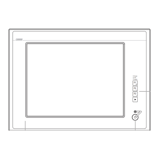
Page 40: Bedien− Und Anzeigeelemente
Bedienung Bedien− und Anzeigeelemente Panel−PC EL 870 / EL 1700 / EL 1700s / EL 2700 / EL 5700 / EL 9700 Bedien− und Anzeigeelemente 6.2.1 Panel−PC EL 870 / EL 1700 / EL 1700s / EL 2700 / EL 5700 / EL 9700... -
Page 41: Panel−Pc El 5720
Bedienung Bedien− und Anzeigeelemente Panel−PC EL 5720 6.2.2 Panel−PC EL 5720 Power Fail Enter Status ELx7xx010 Pos. Bezeichnung Funktion Standard−Modus Service−Modus Modus einschalten: "[" 5 s drücken Modus ausschalten: "[" drücken oder 35 s warten Display applikationsabhängig Status−LEDs Power (grün): Leuchtet, wenn die Versorgungsspannung vorhanden ist. -
Page 42: Panel−Pc El 1750 / El 1750S / El 2750 / El 5750
Bedienung Bedien− und Anzeigeelemente Panel−PC EL 1750 / EL 1750s / EL 2750 / EL 5750 6.2.3 Panel−PC EL 1750 / EL 1750s / EL 2750 / EL 5750 Pg Up Power Fail Status Home Pg Dn Ctrl Menu Shift Space Alpha Enter... - Page 43 Bedienung Bedien− und Anzeigeelemente Panel−PC EL 1750 / EL 1750s / EL 2750 / EL 5750 Pos. Bezeichnung Funktion Standard−Modus Alpha−Modus Service−Modus Modus einschalten: "Alpha−Taste" drücken (LED "Menu−Taste" drücken leuchtet) Modus ausschalten: "Alpha−Taste" drücken (LED "Menu−Taste" drücken oder erloschen) 35 s warten Display applikationsabhängig Status−LEDs...
-
Page 44: Panel−Pc El 5770
Bedienung Bedien− und Anzeigeelemente Panel−PC EL 5770 6.2.4 Panel−PC EL 5770 & § " > < Power Fail Status Einfg Entf Bild Alt Gr Pos 1 Ende Bild Strg Ü € Ö Ä Enter ß Space μ ELx7xx009 LDCDS−ELx7xx DE/EN 4.0... - Page 45 Bedienung Bedien− und Anzeigeelemente Panel−PC EL 5770 Pos. Bezeichnung Funktion Standard−Modus Alpha−Modus Service−Modus Modus einschalten: "Alpha−Taste" drücken (LED "Menu−Taste" drücken leuchtet) Modus ausschalten: "Alpha−Taste" drücken (LED "Menu−Taste" drücken oder erloschen) 35 s warten Display applikationsabhängig Status−LEDs Power (grün): Leuchtet, wenn die Versorgungsspannung vorhanden ist. Fail (rot): Leuchtet, wenn ein Fehler in der Stromversorgung vorliegt;...
-
Page 46: Wartung
Wartung Wartung Stop! Kurzschluss und statische Entladungen Das Gerät enthält Bauelemente, die bei Kurzschluss oder statischer Entladung gefährdet sind. Mögliche Folgen: Das Gerät oder Teile davon werden zerstört. ƒ Schutzmaßnahmen: Bei allen Arbeiten am Gerät, immer Spannungsversorgung abschalten (Netz ƒ und eine evtl. -
Page 47: Kontrollarbeiten
Wartung Kontrollarbeiten Kontrollarbeiten Das Gerät ist wartungsfrei. Trotzdem müssen Sie in regelmäßigen und unter Berücksichti- gung der Umgebungsbedingungen ausreichend kurzen Intervallen eine Sichtprüfung durchführen. Kontrollieren Sie: Entspricht die Umgebung des Gerätes noch den in den Technischen Daten ƒ genannten Einsatzbedingungen? Behindert kein Staub oder Schmutz die Wärmeabfuhr des Gerätes? ƒ... -
Page 48: Instandsetzung
Wartung Instandsetzung PC−Gehäuse demontieren Instandsetzung 7.3.1 PC−Gehäuse demontieren Mit DVD−Laufwerk ‚ ƒ „ ELx7xx−013 So gehen Sie vor, wenn ein DVD−Laufwerk montiert ist: 1. Netzkabel 0 abziehen (¶ 35) 2. DVD−Laufwerk 1 demontieren: – Befestigungsschraube 2 lösen. – DVD−Laufwerk nach rechts schieben. –... - Page 49 Wartung Instandsetzung PC−Gehäuse demontieren Ohne DVD−Laufwerk ƒ ‚ ELx7xx−015 So gehen Sie vor, wenn kein DVD−Laufwerk montiert ist: 1. Netzkabel 0 abziehen (¶ 35). 2. Nur bei lüfterlosen Geräten: Drei Schrauben 1 lösen. 3. Gehäuse 2 abnehmen: – Vier Schrauben 3 lösen. –...
-
Page 50: Pc−Gehäuse Montieren
Wartung Instandsetzung PC−Gehäuse montieren 7.3.2 PC−Gehäuse montieren Mit DVD−Laufwerk ‚ ƒ „ ELx7xx−014 So gehen Sie vor, wenn ein DVD−Laufwerk montiert ist: 1. Gehäuse 0 aufsetzen: – Flachbandkabel 1 durch die Gehäuseöffnung führen und Gehäuse 0 vorsichtig auf das Unterteil setzen. –... - Page 51 Wartung Instandsetzung PC−Gehäuse montieren Ohne DVD−Laufwerk ‚ ƒ ELx7xx−016 1. Gehäuse 0 aufsetzen: – Gehäuse 0 vorsichtig auf das Unterteil setzen. – Vier Schrauben 1 montieren. 2. Nur bei lüfterlosen Geräten: Drei Schrauben 2 eindrehen und fest anziehen. Der innenliegende Kühlkörper muss fest mit dem Gehäuse verbunden sein. Andern- falls wird die Wärme nicht ausreichend abgeführt, und das Gerät kann beschädigt werden.
-
Page 52: Batterie Wechseln
Wartung Instandsetzung Batterie wechseln 7.3.3 Batterie wechseln Gefahr! Feuer− und Explosionsgefahr Auf dem Baseboard (¶ 16) befindet sich eine Batterie zum Puffern der Uhr (RTC) nach dem Ausschalten des Gerätes. Mögliche Folgen: Die Verwendung von nicht zugelassenen Batterien oder eine falsche ƒ... -
Page 53: Sicherung Wechseln
Der fehlerfreie Betrieb ist nicht sichergestellt. Schutzmaßnahmen: Die Sicherung darf nur durch zugelassene Typen ersetzt werden. ƒ Bei sicherheitskritischen Anwendungen muss das Gerät nach einem ƒ Sicherungsausfall durch Lenze überprüft werden. Zugelassene Typen: Littelfuse, Serie 154, 4 A ƒ FAN3 FAN2... -
Page 54: Stichwortverzeichnis
− EL 5720, 41 − Entsorgung, 11 − EL 5770, 44 Einsatzbedingungen, − Funkstörungen, 11 Montagebedingungen − EL 870, 40 − Gewicht, 26 − EL 9700, 40 , 42 − Einbaulage, 21 − Übersicht, 4 − Einbauort, 21 Approbation, 21 Gewicht, Gerät, 26... - Page 55 − EL 5770 USV, 17 − Definition, 9 19"−Rack−Montage, 32 Schalttafel−Montage, 31 USV−Anschluss, 36 − Gestaltung, 9 − EL 870, 30 Sicherung, wechseln, 53 − EL 9700, 31 Smart Cool, 19 Verhalten im Fehlerfall, 11 Software − Betriebssystem, 18 Versorgung, 24 Netzanschluss, 35 −...
- Page 56 Screw clamp fixings DVD drive (option) Controls and displays on the front face Validity information These instructions are valid for ƒ EL 870 ƒ EL 1700, EL 1700s ƒ EL 1750, EL 1750s ƒ EL 2700 ƒ EL 2750 ƒ EL 5700 ƒ...
- Page 57 ‚ Type code 34xx Device type 3400 = EL 870 3401 = EL 1700 3402 = EL 1700s 3403 = EL 2700 3404 = EL 5700 3405 = EL 9700 3406 = EL 5720 3407 = EL 1750 3408 = EL 1750s...
- Page 58 01/2013 TD29 EL 5720: Assignment of function and special keys changed 0Fig. 0Tab. 0 Tip! Documentation and software updates for further Lenze products can be found on the Internet in the "Services & Downloads" area under http://www.Lenze.com LDCDS−ELx7xx DE/EN 4.0...
- Page 59 ............4.3.1 Panel PC EL 870 / EL 1700(s) / EL 1750(s) ......
- Page 60 ..........6.2.1 Panel PC EL 870 / EL 1700 / EL 1700s / EL 2700 / EL 5700 / EL 9700 ..
-
Page 61: Safety Instructions
Safety instructions Notes used Safety instructions Notes used The following pictographs and signal words are used in this documentation to indicate dangers and important information: Safety instructions Structure of safety instructions: Danger! (characterises the type and severity of danger) Note (describes the danger and gives information about how to prevent dangerous situations) Pictograph and signal word... -
Page 62: General Safety Instructions
Safety instructions General safety instructions General safety instructions The device must be installed and maintained by qualified, skilled personnel familiar ƒ with the applicable national standards. The device is classified as a class A device and can cause radio interference in ƒ... -
Page 63: Device Description
After receipt of the delivery, check immediately whether the items match the accompanying papers. We do not accept any liability for deficiencies claimed subsequently. Claim visible transport damage immediately to the forwarder ƒ visible deficiencies/incompleteness immediately to your Lenze ƒ representative. LDCDS−ELx7xx DE/EN 4.0... -
Page 64: Application As Directed
Device description Application as directed Application as directed The panel PC is used as directed if it solely is used for implementing operating concepts or for presenting information in usual industrial and commercial fields. A different use, or one beyond these purposes, is not permissible. A use that is not intended also includes a use harbouring fatal risks or dangers which, without the provision of exceptionally high safety measures, may result in death, injury or damage to material assets. -
Page 65: Standard Devices
Device description Standard devices Standard devices Features Design ƒ – PC housing made of sheet steel, in the case of passive cooling partly of aluminium – Front frame made of anodised and etched aluminium – Front with polyester foil Mounting ƒ... - Page 66 Device description Standard devices Overview Panel PC EL 870 / EL 1700 / EL 1700s / EL 2700 / EL 5700 / EL 9700 EL 870: 8" VGA touchscreen EL 1700: 10.4" VGA touchscreen EL 1700s: 10.4" SVGA touchscreen EL 2700: 12.1" SVGA touchscreen EL 5700: 15"...
- Page 67 Device description Standard devices Panel PC EL 5770 15" XGA touchscreen 12 freely assignable function keys Numerical keypad, control keys, level switch key alpha & MF/2 keyboard " § > < Power Fail Status Einfg Entf Bild Alt Gr Pos 1 Ende Bild Strg...
-
Page 68: Baseboard
Device description Baseboard Baseboard FLAT-PANEL-LVDS FAN0 POWER EPC50 FAN3 FAN2 CR2450 FAN1 COM1 ACCU RESET CF-CARD POWER CS57x0−018 Hard disk (option) ETX module (more detailed information can be found in the ETX module documentation manual provided on CD) Battery ( ^ 104) ACU UPS control unit ( ^ 69) Fuse ( ^ 105) PCI module card slot... -
Page 69: Acu Ups Control Unit (Option)
The optional ACU UPS Control Unit in connection with a battery pack or capacitor pack expands the Industrial PC by one UPS functionality. The ACU UPS Control Unit is either equipped as default or can be retrofitted by the Lenze service. -
Page 70: Software
Device description Software Operating system (accessories) Software 2.6.1 Operating system (accessories) The operating systems listed below can be run on the industrial PC. If ordered, they will be delivered pre−installed on a storage medium. Operating system Description Delivered on storage medium ââ... -
Page 71: Fan Monitoring With "Smart Cool" And "Fan Service" (Option)
The "FAN Service" runs in the background and has no user interface. The "LogFanService.txt" log file can be found under ... Windows XP (Embedded) in the "Smart Cool" program folder ƒ (e.g. "x:\Programs\Lenze\SmartCool\) Windows CE in the "x:\Storage\DeviceScanner\" folder ƒ Note! In order that the log files will not get too long, their data are moved to the "LogFanService.bak"... - Page 72 Fan monitoring with "Smart Cool" and "FAN Service" (option) Installation notes If you have purchased the operating system pre−installed on a storage medium from Lenze, the fan monitoring software has already been installed. In all other cases, you can find the software on the driver CD of your industrial PC. The...
-
Page 73: Technical Data
Technical data General data and operating conditions Technical data General data and operating conditions Conformity and approval Conformity EN 61000 6−4 EMC Directive Class A, industrial premises EN 61000 6−2 Approbation UL 508 Programmable Controllers (File−No. E236341) CSA C22.2 Protection of persons and equipment Safety VDE0805 (EN60950), VDE0870, UL... - Page 74 Technical data General data and operating conditions Note! The failure probability of an electronic component increases with the ambient temperature to which the component is subjected. Regarding the serviceability and reliability, particular attention should be paid to the cooling of the device. For every application, you should take care to keep the heating of the device as low as possible.
- Page 75 Technical data General data and operating conditions Permissible ambient temperatures for systems with "Smart Cool" cooling Standard device Up to 1 GB 40−GB hard 40−GB hard DVD drive DVD drive disk disk for (read only) (read and continuous write) With CF card operation 20−GB hard (24/7) *...
-
Page 76: Electrical Data
Device Fuse Buffer battery Voltage Current at 24 V Type Type Service life [V DC] [years] EL 870 EL 1700 EL 1700s EL 1750 EL 1750s EL 2700 ^ 105 ^ 104 24 (+18 ... 30) > 6 (25 °C) - Page 77 Technical data Electrical data Interfaces Type Connection RS232 Sub−D plug, 9−pole Ethernet 10/100 Mbit RJ45 socket Type A socket PS/2 Standard PS/2 socket, 6−pole PCI module card slot MC fieldbus modules Exchange Compact Flash Compact Flash slot (types I and II; not for Intelâ Core Duo able disk processor) storage...
-
Page 78: Mechanical Data
Technical data Mechanical data Mechanical data Designs and weights Front frame / housing Touchscreen Mass [kg] EL 870 EL 1700 EL 1700s EL 1750 EL 1750s EL 2700 Aluminium/sheet steel Polyester foil EL 2750 EL 5700 EL 5720 EL 5750... - Page 79 Technical data Mechanical data CD/DVD 27.5 CD/DVD ELx7xx−003 All dimensions in millimetres. Dimensions [mm] EL 870 EL 1700 EL 1700s EL 1750 EL 1750s EL 2700 EL 2750 EL 5700 EL 5720 310 (7 U) EL 5750 EL 5770 399 (9 U) EL 9700 LDCDS−ELx7xx DE/EN 4.0...
-
Page 80: Mechanical Installation
Mechanical installation Important notes Mechanical installation Important notes The installation must be carried out by qualified, skilled personnel familiar with the applicable national standards. Stop! Sensitive front frame gasket During mounting, the gasket of the front frame is exposed and can be damaged. -
Page 81: Mounting Cutout
Mechanical installation Mounting cutout Mounting cutout £ 5 ELx7xx−004 Mounting cutout Outline of front panel Control board All dimensions in millimetres. Dimensions [mm] EL 870 246.0 − 188.0 − − − − − EL 1700 305.0 − 228.0 − −... -
Page 82: Mounting Steps
Mechanical installation Mounting steps Panel PC EL 870 / EL 1700(s) / EL 1750(s) Mounting steps 4.3.1 Panel PC EL 870 / EL 1700(s) / EL 1750(s) Proceed as follows for the mounting: 1. Cut the mounting cutout into the control board (¶ 81). -
Page 83: Panel Pc El 2700 / El 2750 / El 5700 / El 5720 / El 5750 / El 5770 / El 9700
Mechanical installation Mounting steps Panel PC EL 2700 / EL 2750 / EL 5700 / EL 5720 / EL 5750 / EL 5770 / EL 9700 4.3.2 Panel PC EL 2700 / EL 2750 / EL 5700 / EL 5720 / EL 5750 / EL 5770 / EL 9700 Note! The EL 5720, EL 5750 and EL 5770 types can be installed in any control board and in 19"... - Page 84 Mechanical installation Mounting steps Panel PC EL 2700 / EL 2750 / EL 5700 / EL 5720 / EL 5750 / EL 5770 / EL 9700 Installation in 19" mounting racks (EL 5720, EL 5750 and EL 5770 only) Proceed as follows for the mounting: 1.
-
Page 85: Electrical Installation
Electrical installation Important notes Electrical installation Important notes The installation must be carried out by qualified, skilled personnel familiar with the applicable national standards. Stop! Sensitive front frame gasket During mounting, the gasket of the front frame is exposed and can be damaged. - Page 86 Electrical installation Important notes Stop! Short circuit and static discharge The device contains components which are endangered in the case of short circuit or static discharge. Possible consequences: The device or parts of it are destroyed. ƒ Protective measures: When working on the device, always switch off the voltage supply (mains ƒ...
-
Page 87: Connecting The Supply Voltage
Electrical installation Connecting the supply voltage Mains connection (X101) Connecting the supply voltage 5.2.1 Mains connection (X101) Stop! No device protection against excessive input voltage The voltage input is not fused internally. Possible consequences: The device can be destroyed when the input voltage is too high. ƒ... -
Page 88: Ups−Pack Connection (X102)
Electrical installation Connecting the supply voltage UPS−PACK connection (X102) 5.2.2 UPS−PACK connection (X102) Description Connection type Cable type EPC5x−ACU Connection of battery pack (included in delivery of (^ LDCDS−2700) or capacitor 2−pin socket battery/capacitor pack; pack (^ LDCDS−2701) length 2.5 m; extension cable available) IPC001 LDCDS−ELx7xx DE/EN 4.0... -
Page 89: Connecting External Devices
Electrical installation Connecting external devices PS/2 interface (X108) Connecting external devices 5.3.1 PS/2 interface (X108) Description Connection type Cable type PS/2 mouse (a keyboard and a mouse can PS/2 connection 6−pin, mini DIN be connected via a PS/2 Y cable) IPC001 5.3.2 Serial interface (X103) -
Page 90: Usb Interface On The Front Face (Option)
Electrical installation Connecting external devices USB interface on the front face (option) 5.3.6 USB interface on the front face (option) Description Connection type Cable type USB host connection with USB−A socket USB cable with USB−A plug IP65 cover cap EL100−013 Note! If you use USB interfaces routed to outside, the data integrity cannot be guaranteed. -
Page 91: Operation
Operation Important notes Operation Important notes Stop! Sensitive touchscreen surface The touchscreen foil is very sensitive to external forces and can be damaged by improper handling. Possible consequences: The touchscreen foil becomes damaged, scratched or dull. ƒ Protective measures: Avoid contact of the touchscreen foil with pointed or hard objects. ƒ... -
Page 92: Controls And Displays
Operation Controls and displays Panel PC EL 870 / EL 1700 / EL 1700s / EL 2700 / EL 5700 / EL 9700 Controls and displays 6.2.1 Panel PC EL 870 / EL 1700 / EL 1700s / EL 2700 / EL 5700 / EL 9700... -
Page 93: Panel Pc El 5720
Operation Controls and displays Panel PC EL 5720 6.2.2 Panel PC EL 5720 Power Fail Enter Status ELx7xx010 Pos. Designation Function Standard mode Service mode Switch on mode: Press "[" for 5 s Switch off mode: Press "[" or wait for 35 s Display Application−dependent Status LEDs... -
Page 94: Panel Pc El 1750 / El 1750S / El 2750 / El 5750
Operation Controls and displays Panel PC EL 1750 / EL 1750s / EL 2750 / EL 5750 6.2.3 Panel PC EL 1750 / EL 1750s / EL 2750 / EL 5750 Pg Up Power Fail Status Home Pg Dn Ctrl Menu Shift Space... - Page 95 Operation Controls and displays Panel PC EL 1750 / EL 1750s / EL 2750 / EL 5750 Pos. Designation Function Standard mode Alpha mode Service mode Switch on mode: Press "alpha key" (LED is on) Press "menu key" Switch off mode: Press "alpha key"...
-
Page 96: Panel Pc El 5770
Operation Controls and displays Panel PC EL 5770 6.2.4 Panel PC EL 5770 & § " > < Power Fail Status Einfg Entf Bild Alt Gr Pos 1 Ende Bild Strg Ü € Ö Ä Enter ß Space μ ELx7xx009 LDCDS−ELx7xx DE/EN 4.0... - Page 97 Operation Controls and displays Panel PC EL 5770 Pos. Designation Function Standard mode Alpha mode Service mode Switch on mode: Press "alpha key" (LED is on) Press "menu key" Switch off mode: Press "alpha key" (LED is off) Press "menu key" or wait for 35 s Display Application−dependent...
-
Page 98: Maintenance
Maintenance Maintenance Stop! Short circuit and static discharge The device contains components which are endangered in the case of short circuit or static discharge. Possible consequences: The device or parts of it are destroyed. ƒ Protective measures: When working on the device, always switch off the voltage supply (mains ƒ... -
Page 99: Regular Checks
Maintenance Regular checks Regular checks The device is free of maintenance. Nevertheless, visual inspections should be carried out at regular intervals which must not be too long, depending on the ambient conditions. Please check the following: Does the environment of the device meet the operating conditions specified in the ƒ... -
Page 100: Repair
Maintenance Repair Remove the PC housing Repair 7.3.1 Remove the PC housing With DVD drive ‚ ƒ „ ELx7xx−013 Proceed as follows when a DVD drive is mounted: 1. Remove the mains cable 0 (¶ 87) 2. Remove the DVD drive 1: –... - Page 101 Maintenance Repair Remove the PC housing Without DVD drive ƒ ‚ ELx7xx−015 Proceed as follows when no DVD drive is mounted: 1. Remove the mains cable 0 (¶ 87). 2. Only for fanless devices: Loosen the three screws 1. 3.
-
Page 102: Mount The Pc Housing
Maintenance Repair Mount the PC housing 7.3.2 Mount the PC housing With DVD drive ‚ ƒ „ ELx7xx−014 Proceed as follows when a DVD drive is mounted: 1. Mount the housing 0: – Pass the ribbon cable 1 through the housing aperture and carefully place the housing 0 on the housing base. - Page 103 Maintenance Repair Mount the PC housing Without DVD drive ‚ ƒ ELx7xx−016 1. Mount the housing 0: – Carefully place the housing 0 on the housing base. – Screw in the four screws 1. 2. Only for fanless devices: Screw in the three screws 2 and tighten them. The internal heatsink must be firmly connected with the housing.
-
Page 104: Battery Change
Maintenance Repair Battery change 7.3.3 Battery change Danger! Danger of fire and explosion On the baseboard (¶ 68) there is a battery for buffering the clock (RTC) when the device has been switched off. Possible consequences: The use of other batteries than the approved ones or improper handling can ƒ... -
Page 105: Fuse Change
The fuse may only be replaced by an approved type. ƒ In the case of safety−critical applications the device has to be checked by ƒ Lenze after the blowing of fuses. Approved types: Littelfuse, series 154, 4 A ƒ FAN3... -
Page 106: Index
− Fuse, 105 Capacitor pack, 69 − EL 5770, 96 − Mount the PC housing, 102 Chemical resistance, 73 − EL 870, 92 − Remove the PC housing, 100 − EL 9700, 92 , 94 Class of protection, 73 Mechanical data, 78 −... - Page 107 Control board mounting, 83 RS232 connection, 89 − EL 5770 19" rack mounting, 84 Control board mounting, 83 UPS, 69 − EL 870, 82 Safety, 73 − EL 9700, 83 UPS connection, 88 Safety instructions, 61 USB connection − Application as directed, 64 −...
- Page 108 © 01/2013 Lenze Automation GmbH Service Lenze Service GmbH Hans−Lenze−Str. 1 Breslauer Straße 3 D−31855 Aerzen D−32699 Extertal Germany Germany +49 (0)51 54 / 82−0 00 80 00 / 24 4 68 77 (24 h helpline) Ê Ê +49 (0)51 54 / 82 − 28 00 +49 (0)51 54 / 82−11 12...
Need help?
Do you have a question about the EL 870 and is the answer not in the manual?
Questions and answers