Table of Contents
Advertisement
Quick Links
^1
USER MANUAL
^2
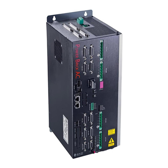
Power Brick AC
^2
Power Brick AC
Single Source Machine Control
21314 Lassen St. Chatsworth, CA 91311 // Tel. (818) 998-2095 Fax. (818) 998-7807 //
^3
Programmable Servo Amplifier
^3
Low Voltage Programmable Servo Amplifier
^4
PBAx-xxx-xxx-xxxxxxx
^4
^5
July 19, 2017
^5
January 2, 2014
..............................................................................
DELTA TAU
Data Systems, Inc.
NEW IDEAS IN MOTION ...
Power // Flexibility // Ease of Use
www.deltatau.com
Advertisement
Table of Contents

Related Manuals for Delta Tau Power Brick AC


Summary of Contents for Delta Tau Power Brick AC
- Page 1 USER MANUAL Power Brick AC Power Brick AC Programmable Servo Amplifier Low Voltage Programmable Servo Amplifier PBAx-xxx-xxx-xxxxxxx July 19, 2017 January 2, 2014 DELTA TAU Data Systems, Inc. NEW IDEAS IN MOTION … ……………………………………………..…...………………. Single Source Machine Control Power // Flexibility // Ease of Use 21314 Lassen St.
- Page 2 © 2017 Delta Tau Data Systems, Inc. All rights reserved. This document is furnished for the customers of Delta Tau Data Systems, Inc. Other uses are unauthorized without written permission of Delta Tau Data Systems, Inc. Information contained in this manual may be updated from time-to-time due to product improvements, etc., and may not conform in every respect to...
- Page 3 Power Brick AC User Manual Safety Instructions Qualified personnel must transport, assemble, install, and maintain this equipment. Properly qualified personnel are persons who are familiar with the transport, assembly, installation, and operation of equipment. The qualified personnel must know and observe the following standards and regulations: IEC364resp.CENELEC HD 384 or DIN VDE 0100...
- Page 4 Power Brick AC User Manual MANUAL REVISION HISTORY REV DESCRIPTION DATE CHANGE APPROVED Preliminary 05/28/2014 Released 07/20/2015 Updated I/O & Flags electrical specifications Updated power–up procedure Updated absolute power-on position and ongoing phase position Added A16 connector description Corrected serial clock/data pinouts...
-
Page 6: Table Of Contents
8-Axis Power Brick AC ........................23 Mounting ...........................24 Physical Specifications ......................25 4–axis Power Brick AC ........................25 6– / 8–axis Power Brick AC ......................26 CONNECTIONS AND SOFTWARE SETUP ............... 27 A1 – A8: Motor / Brake Wiring ....................27 Configuring the Brake Output ......................29 Motor Cable, Noise Elimination ....................... - Page 7 Power Brick AC User Manual X1 - X8: Encoder Feedback, Sinusoidal ..................50 Configuring Sinusoidal Encoders ..................... 51 Sinusoidal Counts per User Units ..................... 52 X1 – X8: Encoder Feedback, Resolver..................54 Setting up Resolvers ......................... 55 Configuring Resolver ECT ........................ 56 Resolver Counts per User Units ......................
- Page 8 Power Brick AC User Manual ETH 0/1: Ethernet Connections ....................117 ETH 0 Ethernet Port ........................117 ETH 1 Ethernet Port ........................117 ETH 2/3: EtherСAT Connections..................... 118 RS-232 Connection ......................... 119 MANUAL MOTOR SETUP ....................120 Global Reset ........................... 121 Dominant Clock Frequencies ....................
- Page 9 Power Brick AC User Manual D1: Error Codes ........................174 Step and Direction, PFM Output ..................... 175 Sinusoidal Encoder Bias Corrections ..................178 Reversing Motor Jogging Direction ..................184 PLC Timer Delay ........................185 Encoder Count Error ....................... 186 Encoder Loss Detection ......................187 Digital Quadrature .........................
- Page 10 Power Brick AC User Manual Channel Status Elements ......................220 BrickAC.Chan[j].I2tExcess......................220 BrickAC.Chan[j].IgbtOverTempFault ..................... 221 BrickAC.Chan[j].IgbtTemp......................221 BrickAC.Chan[j].InvalidPwmFreq ....................222 BrickAC.Chan[j].OverCurrent ....................... 223 BrickAC.Chan[j].OverTemp ......................223 BrickAC.Chan[j].PwmFreq ......................224 APPENDIX A: DIGITAL INPUTS SCHEMATIC ............. 225 APPENDIX B: DIGITAL OUTPUTS SCHEMATIC ............226 APPENDIX C: ANALOG I/OS SCHEMATICS ..............
-
Page 11: Introduction
Power PMAC motion controller with high performance IGBT-based drives resulting into a 4-, 6-, or 8-axis compact smart drive. The Power Brick AC is designed for up to 240 VAC main input power. It supports virtually any type of feedback device and can drive directly the following types of motors: ➢... -
Page 12: Downloadable Power Pmac Script
Power Brick AC User Manual Downloadable Power PMAC Script Some code snippets may require the user to input specific information pertaining to their system application. Occasionally, they are denoted in a commentary ending with – User Input. Caution This manual contains downloadable code snippets in Power PMAC script. These examples can be copied and pasted into the editor area of the IDE software. -
Page 13: Receiving And Unpacking
The components built into electrical equipment or machines can be used only as integral components of such equipment. • The Power Brick AC must not be operated on power supply networks without a ground or with an asymmetrical ground. •... -
Page 14: Specifications
Power Brick AC User Manual SPECIFICATIONS Part Number Designation B C D E F G P B A Option D Option E Option Option B Option C 800 MHz 1 GB 1 1 GB 0 1 Gbs EtherNet axis Flash... - Page 15 Power Brick AC User Manual B C D E F G P B A Option I Axis Axis Encoder Digital MACRO Nodes True DAC Filtered PWM Analog Inputs I/Os Servo / IOs Analog Out Analog Out Inputs Relays 16/8 16/8...
-
Page 16: Power Brick Ac Configuration
Power Brick AC User Manual Power Brick AC Configuration The Power Brick AC comes standard with a powerful set of hardware and software capabilities, plus a full set of options. Standard Configuration 800 MHz Single-Core Power PC 460EX. 2 GB DDRAM3 active, 1 GB NAND Flash non-volatile. -
Page 17: Options
Yaskawa II/III/V with position reset and fault clear o Tamagawa FA-Coder with servo clock output o SSI (no capabilities over Power Brick AC’s built-in interface) o Panasonic (no capabilities over Power Brick AC’s built-in interface) o Mitutoyo (no capabilities over Power Brick AC’s built-in interface) Amplifier 4 additional amplifier axes, each at 5/10 A or 8/16 A with 24 V brake output. -
Page 18: Configuration Notes
Additionally, any of the listed optional protocols can be ordered (in sets of 4 channels: 1 – 4 or 5 – 8). These are processed on what is known as the ACC–84B (piggy back inside the Power Brick AC). Some protocols may overlap between the Gate3 and ACC–84B. Users may need new, updated protocols, or additional serial data information which may not be available with the standard Gate3 protocol implementation. -
Page 19: Environmental Specifications
Power Brick AC User Manual Environmental Specifications Specification Description Range Minimum operating temperature 0°C (32 °F) Ambient operating Temperature EN50178 Class 3K3 – IEC721-3-3 Maximum operating temperature 45°C (113 °F) Minimum Storage temperature -25°C (-13 °F) Storage Temperature Range EN 50178 Class 1K4 – IEC721-3-1/2 Maximum Storage temperature 70°C (158 °F) -
Page 20: Protection Specifications
Power Brick AC User Manual Protection Specifications The internal I T applies to and protects the amplifier power blocks. The software PMAC I T (described in a later section) must be configured properly to protect against motor / equipment damage. -
Page 21: Electrical Specifications
Power Brick AC User Manual Electrical Specifications 4-Axis Power Brick AC PBA4-xxx-xxx-5xxxxxx PBA4-xxx-xxx-8xxxxxx Output Continuous Current per Axis Output Peak Current (2 sec) per Axis Rated Input Current @ 240 VAC 3-phase (All Axes) 15.625 25.0 Max ADC (I T Settings) -
Page 22: 6-Axis Power Brick Ac
Power Brick AC User Manual 6-Axis Power Brick AC PBA6-xxx-xxx-5xxxxxx PBA6-xxx-xxx-8xxxxxx Axes Output Continuous Current per Axis Output Peak Current (2 sec) per Axis 15.625 46.875 25.0 46.875 Max ADC (I T Settings) Rated Input Current @ 240 VAC 3-phase (All Axes) -
Page 23: 8-Axis Power Brick Ac
Power Brick AC User Manual 8-Axis Power Brick AC PBA8-xxx-xxx-55 PBA8-xxx-xxx-88 PBA8-xxx-xxx-58 PBA8-xxx-xxx-85 1 – 4 5 – 8 1 – 4 5 – 8 1 – 4 5 – 8 1 – 4 5 – 8 Axes Output Continuous Current per Axis... -
Page 24: Mounting
Power Brick AC User Manual Mounting The location of the Power Brick AC is important. Installation should be in an area that is protected from direct sunlight, corrosives, harmful gases or liquids, dust, metallic particles, and other contaminants. Exposure to these can reduce the operating life and degrade performance of the drive. -
Page 25: Physical Specifications
Power Brick AC User Manual Physical Specifications 4–axis Power Brick AC 4 x M4 4.00" (101.6 mm) 1.88" (47.752 mm) 14.75" (374.65 mm) 14.25" (361.95 mm) 7.65" 5.934" (194.31 mm) (150.72 mm) Specifications... -
Page 26: 8-Axis Power Brick Ac
Power Brick AC User Manual 6– / 8–axis Power Brick AC 6.50" 4 x M4 (165.1 mm) 14.75" 14.25" (374.65 mm) (361.95 mm) 7.65" 9.50" (194.31 mm) (241.20 mm) 9.53" (242.04 mm) Specifications... -
Page 27: Connections And Software Setup
Power Brick AC User Manual CONNECTIONS AND SOFTWARE SETUP Installation of electrical control equipment is subject to many regulations including national, state, local, and industry guidelines and rules. General recommendations can be stated but it is important that the installation be carried out in accordance with all regulations Warning pertaining to the installation. - Page 28 Power Brick AC User Manual If the motor brake is rated to voltage level other than 24 VDC, or draws more than 1 A at 24 V, then the power supply provided through A12 can be used to toggle an external relay which routes the brake power from a dedicated power supply –...
-
Page 29: Configuring The Brake Output
Power Brick AC User Manual Configuring the Brake Output The brake output is high true. It is 0V when the motor is killed (or OutFlagB = 0) and 24 V when the motor is enabled (or OutFlagB = 1). The necessary settings required to synchronize the enabling and disabling of the motor with the brake output signal are as follows: Motor[1].pBrakeOut = PowerBrick[0].Chan[0].OutFlagB.a... -
Page 30: Motor Cable, Noise Elimination
The connection between the cable shield and the motor frame should be as short as possible). At the Power Brick AC end, make a 360 degree connection between the shield and the chassis ground bar (protection earth). -
Page 31: Motor Selection
Power Brick AC User Manual Motor Selection The Power Brick AC interfaces with a wide variety of motors. It supports virtually any kind of three-phase AC/DC rotary, linear brushless, or induction motors. Using two out of the three phases, it is also possible to drive permanent magnet DC brush motors. - Page 32 Power Brick AC User Manual Required Bus Voltage for Speed and Torque For a required motor Speed, and continuous Torque, the minimum DC Bus Voltage (V ) can be estimated by looking at the equivalent single phase circuit: BEMF Motor...
-
Page 33: A10: Logic Power Input
A10: Logic Power Input A10 is used to bring in the 24 VDC supply powering up the logic portion of the Power Brick AC. This power can remain on regardless of the main AC bus power, allowing the signal electronics to be active while the main motor power is passive. -
Page 34: A11: Safe Torque Off Sto, Dynamic Braking
Power Brick AC User Manual A11: Safe Torque Off STO, Dynamic Braking Connector A11 serves the following functions: ➢ Disabling the Safe Torque Off STO ➢ Arming / using the STO ➢ Using dynamic braking ➢ Wiring the STO feedback (output status) Power Brick units shipped prior to the Q3 2016 had the Dynamic Brake (DYN BRAKE) and STO IN silkscreen etchings reversed. -
Page 35: Disabling The Sto
Power Brick AC User Manual Disabling the STO STO FB STO IN The STO can be fully disabled by tying pins #4 and #5 together. DYN BRAKE All other pins on this connector have no practical use in this mode, and should be left floating. -
Page 36: Wiring And Using The Dynamic Braking
Power Brick AC User Manual Wiring and Using the Dynamic Braking This scheme is used if the application STO FB mandates minimal coasting in an STO IN uncontrolled stop request. DYN BRAKE Some applications may choose to use 24 VDC... -
Page 37: A12: Brake Power (Axes 1 - 4)
Power Brick AC User Manual A12: Brake Power (Axes 1 – 4) A12 is used to supply the +24 VDC brake power for axes 1 – 4. Brakes which require AC voltage, other than 24 VDC, or draw current in excess of (at 24 VDC, per channel) must be powered using a dedicated external power supply and not through A12. -
Page 38: A14: External Shunt Resistor
Delta Tau mating connector P/N: 016-PL0F02-76P A14 is used to wire an external shunt resistor to expel the excess power during demanding deceleration profiles. The 4- and 8-axis Power Brick AC drives are designed for operation with external shunt resistors of 15 Ohms. -
Page 39: A15: Main Bus Power Input
Power Brick AC User Manual A15: Main Bus Power Input A15 is used to bring the main AC/DC bus power into the Power Brick AC. A15: Phoenix Contact 4-pin Female Mating: Phoenix Contact 4-pin Male Symbol Function Three Phase Single Phase... -
Page 40: Advised Power On/Off Sequence
Caution Powering up the Power Brick AC must obey the following sequence: 1. Make sure main bus power is disconnected (e.g. E-Stop engaged) 2. Apply 24 VDC logic power (A10). The STO and Dynamic Brake states are irrelevant at this point. -
Page 41: Recommended Main Bus Power Wiring / Protection
Use a heavy gauge ground earth conductors made up of many strands of fine conducts. • The Power Brick AC is brought to the earth-ground via one or two wire(s) connected to the M4 mounting stud(s) through a heavy gauge multi-strand conductor to the central earth-ground. It can alternately be tied to the motor grounding bar. - Page 42 Power Brick AC User Manual Three-Phase Main AC Power Wiring Diagram 3-PHASE TRANSFORMER Up to 240 VAC PROTECTION EARTH Magnetic Contactor (E-Stop Circuit) EMC/EMI FILTER Shielded Phase-Phase Twisted Voltage Suppressors Single-Phase Main AC Power Wiring Diagram Single Phase Source Up to 240 VAC...
- Page 43 PBA6-xxx-xxx-85 Specific applications fuse sizing can be done using the following equations. Take, as an example, a 4-axis Power Brick AC (5/10 A) on 240 VAC bus, and driving 4 motors (5 A continuous current rating): DC Bus Voltage: = √2 × V = 1.414 ×...
- Page 44 Bus Power Cables The Power Brick AC electronics create a DC bus by rectifying the incoming AC lines. The current flow into the drive is not sinusoidal but rather a series of narrow, high-peak pulses. Keeping the incoming impedance small is essential for not hindering these current pulses.
-
Page 45: A16: Brake Power (Axes 5 - 8)
Power Brick AC User Manual A16: Brake Power (Axes 5 – 8) A16 is used to supply the +24 VDC brake power for axes 5 – 8. Brakes which require AC voltage, other than 24 VDC, or draw current in excess of (at 24 VDC, per channel) must be powered using a dedicated external power supply and not through A16. -
Page 46: X1 - X8: Encoder Feedback, Digital Quadrature
Power Brick AC User Manual X1 - X8: Encoder Feedback, Digital Quadrature The Power Brick AC processes digital quadrature (also known as incremental) encoder signals by default. It provides up to four counts per square cycle, and extends it using hardware-computed (ASIC) 1/T. - Page 47 Power Brick AC User Manual Quadrature encoders provide two digital signals to determine the position of the motor. These signals are typically 5V TTL/CMOS level. Each nominally with 50% duty cycle, and 1/4 cycle apart. This format provides four distinct states per cycle of the signal, or per line of the encoder. The phase difference of the two signals permits the decoding electronics to discern the direction of travel, which would not be possible with a single signal.
-
Page 48: Configuring Quadrature Encoders
Power Brick AC User Manual Configuring Quadrature Encoders The Power Brick AC firmware is configured to process quadrature incremental encoders by default. This type of encoders is processed as a single 32-bit word in the Encoder Conversion Table (ECT). The 1/T extension is done in the DSPGate3 hardware. - Page 49 “stuck” – and it can react wildly, often causing a runaway Warning condition. With quadrature encoders, the Power Brick AC has the capability of detecting the loss of an encoder signal. This is described in detail in the Encoder Loss Detection section of this manual.
-
Page 50: X1 - X8: Encoder Feedback, Sinusoidal
Power Brick AC User Manual X1 - X8: Encoder Feedback, Sinusoidal The Power Brick AC can process sinusoidal encoders (up to 1.2 V ), and provide high resolution (x peak-peak 16384) interpolated position data. X1-X8: D-sub DA-15F Mating: D-sub DA-15M... -
Page 51: Configuring Sinusoidal Encoders
Power Brick AC User Manual The Power Brick AC can accept “sine” and “cosine” signals Encoder shield (solder to shell) (90° out of phase with each other), of up to 1.2 V (peak-to- Sine + Sine - peak) magnitude. Cosine +... -
Page 52: Sinusoidal Counts Per User Units
Note Sinusoidal Counts per User Units The (Gate 3) ASIC in the Power Brick AC has the capability of computing the sub-count interpolated position in hardware. The sub-count data is then combined with the whole-count data from the quadrature counter... - Page 53 Power Brick AC User Manual Bias Correction The Power Brick AC has the capability of correcting for biases of the cosine / sine signals. These corrections are suitable when interpolating in the DSPGate3 without the ACI (Auto Correcting Interpolator) option.
-
Page 54: X1 - X8: Encoder Feedback, Resolver
Power Brick AC User Manual X1 – X8: Encoder Feedback, Resolver The Power Brick can "optionally" accept resolver encoder input (up to 5 V ) and provide interpolated peak-peak position data. X1-X8: D-sub DA-15F Mating: D-sub DA-15M Primary Alternate Use... -
Page 55: Setting Up Resolvers
Power Brick AC User Manual Setting up Resolvers Configuring a resolver requires setting up the excitation signal control. The excitation signal control element, PowerBrick[].ResolverCtrl, is a 4-channel saved component: Excitation Signal Control Channels 1 – 4 PowerBrick[0].ResolverCtrl Channels 5 – 8 PowerBrick[1].ResolverCtrl... -
Page 56: Configuring Resolver Ect
Power Brick AC User Manual Utilizing the following expression, for channels 1 – 4 as an example: GLOBAL ResExcitDelay; GLOBAL ResExcitMag; GLOBAL ResExcitFreqDiv; ResExcitMag = 3 // [0 - 3] ResExcitFreqDiv = 0 // [0 - 3] ResExcitDelay = 65 // [0 - 255] PowerBrick[0].ResolverCtrl = ResExcitDelay*EXP2(24) + ResExcitMag*EXP2(22) + ResExcitFreqDiv*EXP2(20) -
Page 57: Resolver Absolute Power-On Position
Power Brick AC User Manual Resolver Absolute Power-On Position With resolvers, the absolute position is computed directly from the upper 16 bits of the AtanSumOfSqr register. It is set up using the following key structure elements: ➢ Motor[].pAbsPos = PowerBrick[0].Chan[2].AtanSumOfSqr.a ➢... - Page 58 “stuck” – and it can react wildly, often causing a runaway Warning condition. With Resolvers, the Power Brick AC has the capability of detecting the loss of an encoder signal. This is described in detail in the Encoder Loss Detection section of this manual.
-
Page 59: X1 - X8: Encoder Feedback, Serial
Power Brick AC User Manual X1 – X8: Encoder Feedback, Serial The Power Brick AC, in its standard configuration, accepts a variety of serial encoder protocols. These protocols are built into the DSPGate3. This section discusses the configuration of these serial encoders. - Page 60 Power Brick AC User Manual Quadrature / sinusoidal encoders can be wired and processed simultaneously with serial encoders on the same channel. Note Pins #5, 6, 13, and 14 of the encoder feedback connectors (X1 – X8) share multiple functions: only one of these functions (per channel) can be used –...
-
Page 61: Serial Encoder Control
Power Brick AC User Manual Serial Encoder Control The Serial Encoder Control is a 32-bit, 4-channel (1 – 4, or 5 – 8), structure element. It specifies the protocol type, delay compensation time, trigger edge, trigger clock, and transmission frequency of the 4 serial encoder channels. -
Page 62: Serial Encoder Command
Power Brick AC User Manual Serial Encoder Command The Serial Encoder Command is a 32-bit, channel specific, structure element. It specifies the bit length (resolution), status bits, data type, conversion method, trigger enable, trigger mode, parity, and command code of the serial encoder channel. -
Page 63: Ssi Configuration Example
Power Brick AC User Manual SSI Configuration Example Serial Encoder Control – SSI No trigger delay, rising edge of phase, and 2.5 MHz transmission M = 39 ($27) 0: Phase 0: Rising Protocol: =2 SSI = 2.5 MHz = Delay Serial µsec... -
Page 64: Endat 2.1/2.2 Configuration Example
EnDat 2.1 command codes. However, not all encoders sold as meeting the EnDat 2.2 standard can do this. Note With the Power Brick AC, EnDat additional information is supported via the (optional) ACC-84B serial interface. Note A 37-bit EnDat 2.2 encoder for continuous position reporting:... - Page 65 Power Brick AC User Manual With EnDat 2.2, bit 31 is the StartDelayComp control bit. Setting this bit to 1 starts a delay identification and compensation cycle which measures the propagation delay between the encoder and the controller. The delay is measured three times and the average is used in the compensation. When these calculations are done, the StartDelayComp bit 31 is automatically cleared.
-
Page 66: Hiperface Configuration Example
“daisy-chained” on a single multi-drop interface. While this can be done, it is expected that each channel of the Power Brick AC will be connected to a separate individual encoder, simplifying the wiring. In this configuration, this address field can either match the encoder’s address value (+ $40), or it can be set to $FF (broadcast mode). - Page 67 Power Brick AC User Manual Serial Data Registers – Hiperface The resulting position data, status, and error bits for Hiperface are found in the following Serial Data Registers: PowerBrick[].Chan[].SerialEncDataA Possible Single/Multi-Turn Position PowerBrick[].Chan[].SerialEncDataB Encoder Error Code Connections and Software Setup...
-
Page 68: Yaskawa Sigma I Configuration Example
Power Brick AC User Manual Yaskawa Sigma I Configuration Example Serial Encoder Control – Sigma I Because there is no explicit clock signal with Sigma I, the serial clock frequency is set 20 times higher than the bit transmission frequency to “oversample” the input data stream. For the default 9600 baud transmission of the Sigma I encoder, this clock frequency should be 9.6 x 20 = 192 kHz. - Page 69 Power Brick AC User Manual Serial Data Registers – Sigma I The resulting position data, status, and error bits for Sigma I are found in the following Serial Data Registers: PowerBrick[].Chan[].SerialEncDataA Multi-Turn Position PowerBrick[].Chan[].SerialEncDataB "P" Sign (±) Multi-Turn Position In the Data A register, bits [7 – 0] represent the bits of the ASCII code for the “ones digit” of the turns count, bits [15 –...
-
Page 70: Yaskawa Sigma Ii/Iii/V Configuration Example
Power Brick AC User Manual Yaskawa Sigma II/III/V Configuration Example Serial Encoder Control – Sigma II/III/V No trigger delay, rising edge of phase, and 4.0 MHz transmission: M = 0 0: Phase 0: Rising Protocol: =6 Sigma II/III/V = 4 MHz... - Page 71 Power Brick AC User Manual Yaskawa Sigma II (incremental 17-bit) PowerBrick[].Chan[].SerialEncDataA Single-Turn Position Compensation Position PowerBrick[].Chan[].SerialEncDataB Alarm Code Temperature Yaskawa Sigma III/V (absolute 20-bit) PowerBrick[].Chan[].SerialEncDataA Multi-Turn Position Single-Turn Position PowerBrick[].Chan[].SerialEncDataB Alarm Code Temperature Multi-Turn Position Yaskawa Sigma II/II/V Encoders Alarm Code (Serial Encoder Data B Register)
-
Page 72: Tamagawa Fa-Coder Configuration Example
Power Brick AC User Manual Tamagawa FA-Coder Configuration Example Serial Encoder Control – Tamagawa FA-Coder No trigger delay, rising edge of phase, and 2.5 MHz transmission: M = 1 0: Phase 0: Rising Protocol: =7 Tamagawa = 2.5 MHz = Delay Serial µsec... -
Page 73: Panasonic Configuration Example
Power Brick AC User Manual Panasonic Configuration Example Serial Encoder Control – Panasonic No trigger delay, rising edge of phase, and 2.5 MHz transmission: M = 1 0: Phase 0: Rising Protocol: =8 Panasonic = 2.5 MHz = Delay Serial µsec... - Page 74 Power Brick AC User Manual Serial Data Registers – Panasonic The resulting position data, status, and error bits for Panasonic are found in the following Serial Data Registers: PowerBrick[].Chan[].SerialEncDataA Multi-Turn Position Single-Turn Position Encoder ID Code PowerBrick[].Chan[].SerialEncDataB Status Field Alarm code...
-
Page 75: Mitutoyo Configuration Example
Power Brick AC User Manual Mitutoyo Configuration Example Serial Encoder Control – Mitutoyo No trigger delay, rising edge of phase, and 2.5 MHz transmission: M = 1 0: Phase 0: Rising Protocol: =9 Mitutoyo = 2.5 MHz = Delay Serial µsec... - Page 76 Power Brick AC User Manual Serial Data Registers – Mitutoyo The resulting position data, status, and error bits for Mitutoyo are found in the following Serial Data Registers: PowerBrick[].Chan[].SerialEncDataA Possible Single-Turn/Multi-turn Position PowerBrick[].Chan[].SerialEncDataB Alarm code Encoder ID Status Field Bit #...
-
Page 77: Kawasaki Configuration Example
Power Brick AC User Manual Kawasaki Configuration Example Serial Encoder Control – Kawasaki No trigger delay, rising edge of phase, and 2.5 MHz transmission: M = 1 0: Phase 0: Rising Protocol: =A Kawasaki = 2.5 MHz = Delay Serial µsec... -
Page 78: Serial Encoder Ongoing Position Setup
Power Brick AC User Manual Serial Encoder Ongoing Position Setup For the ongoing "incremental" position data, it is sufficient to process whatever position data (single-turn and/or multi-turn) is available in the serial data A register. The PMAC firmware does not require processing the entire bit length because the difference change in between servo cycles is used to compute the ongoing position. - Page 79 Power Brick AC User Manual Example: A serial encoder with 20 bits of single-turn (or an equivalent 50 nm linear scale) position data located in serial data A register and starting at bit #4. The low nibble may contain other information, irrelevant to position data.
- Page 80 Power Brick AC User Manual Example: A serial encoder with 36 bits of single-turn (or an equivalent 1 nm linear scale) position data located in serial data A and B registers consecutively. PowerBrick[].Chan[].SerialEncDataA PowerBrick[].Chan[].SerialEncDataB Reading and processing the 32 bits of position data in serial data register A is sufficient for producing the proper ongoing position.
- Page 81 Power Brick AC User Manual Example: A 29-bit serial encoder with 17 bits of single-turn and 12 bits of multi-turn position data starting at bit #0 of serial data A register and continuously extending to bit #28. PowerBrick[].Chan[].SerialEncDataA Multi-Turn Position Data Single-Turn Position Data Both single-turn and multi-turn data can be used for ongoing position.
- Page 82 Power Brick AC User Manual Example: A 36-bit serial encoder with 24 bits of single-turn and 12 bits of multi-turn position data starting at bit #0 of serial data A register and continuously extending to bit #3 of serial data register B.
-
Page 83: Serial Encoder Power-On Absolute Position Setup
Power Brick AC User Manual Serial Encoder Power-On Absolute Position Setup The absolute position is computed directly from the serial data registers, and set up using the following key structure elements: ➢ Motor[].pAbsPos, typically = PowerBrick[].Chan[].SerialEncDataA.a ➢ Motor[].AbsPosSf = Motor[].PosSf ➢... - Page 84 Power Brick AC User Manual Example: A serial encoder with 17 bits of binary single-turn (or linear scale), and no multi-turn, position data located in the lower fields of serial data A register. PowerBrick[].Chan[].SerialEncDataA 17 bits 00: unsigned binary Motor[].AbsPosFormat = $...
- Page 85 Power Brick AC User Manual Encoders with no multi-turn position data are set up as unsigned. Note Example: A 29-bit binary serial encoder with 17 bits of single-turn and 12 bits of multi-turn position data starting at bit #0 of serial data A register and continuously extending to bit #28.
- Page 86 Power Brick AC User Manual Example: A 36-bit binary serial encoder with 24 bits of single-turn in the lower fields of serial data register A, and 12 bits of multi-turn position data in the lower fields of serial data register B.
- Page 87 Power Brick AC User Manual Example: A 32-bit Gray code serial encoder with 20 bits of single-turn in serial data register A starting at bit #4, and 12 bits of multi-turn position data in serial data register B starting at bit #8.
- Page 88 Power Brick AC User Manual Example: A 33-bit binary serial encoder (for example, Panasonic) with 17 bits of single-turn and 16 bits of multi-turn position data in the following fields: PowerBrick[].Chan[].SerialEncDataA Multi-Turn Position Data Single-Turn Position Data PowerBrick[].Chan[].SerialEncDataB Multi-Turn Position Data The automatic settings are not suitable for the discontinuity between the single-turn and multi-turn data.
-
Page 89: X9 - X12: Analog Inputs / Outputs
Power Brick AC User Manual X9 – X12: Analog Inputs / Outputs Each of the analog I/O connectors (X9, X10, X11, and X12) provides: ➢ 2 x 16-bit Analog Inputs ➢ 2 x ~14-bit Analog Outputs ➢ 2 x General Purpose Relays ➢... -
Page 90: Setting Up The Analog (Adc) Inputs
Power Brick AC User Manual Setting up the Analog (ADC) Inputs The analog inputs accept ±5 V differential signals, or ±10 V single-ended signals. Differential Analog Input Signal Single Ended Analog Input Signal AGND AGND ADC1- ADC1- ADC1+ ADC1+ 12 11 12 11 For single-ended connections, tie the negative ADC pin to ground. - Page 91 Power Brick AC User Manual The ADC input data must be in the “unpacked” format to be read properly; use PowerBrick[].Chan[].PackInData = 0. Note Raw ADC Data (bits) PowerBrick[0].Chan[0].PackInData = // Unpack Input Data PowerBrick[0].Chan[1].PackInData = // Unpack Input Data PowerBrick[0].Chan[2].PackInData =...
- Page 92 Power Brick AC User Manual GLOBAL ADC1X9Volts = 0; // Voltage input, ADC1 X9 [volt] GLOBAL ADC2X9Volts = 0; // Voltage input, ADC2 X9 [volt] GLOBAL ADC1X10Volts = 0; // Voltage input, ADC1 X10 [volt] GLOBAL ADC2X10Volts = 0; // Voltage input, ADC2 X10 [volt] GLOBAL ADC1X11Volts = 0;...
- Page 93 Power Brick AC User Manual Using the ADC for Servo Feedback Using the ADC data for servo feedback requires bringing it into the Encoder Conversion Table (ECT) into which the motor’s position and velocity elements are assigned to. Example: EncTable[9].Type = EncTable[9].pEnc = PowerBrick[0].Chan[0].AdcAmp[2].a...
-
Page 94: Setting Up The Analog (Dac) Outputs
The analog output circuitry is filtered PWM optimized (in hardware) for a PWM cut off frequency of about 15 kHz. The recommended PWM frequency of 10 kHz in the Power Brick AC should be good enough for general purpose usage. - Page 95 Power Brick AC User Manual Writing directly into PowerBrick[].Chan[].Pwm[3] register to produce voltage output requires shifting left by 16 bits (or multiplying by 65536). Note The command output data must be in the “unpacked” format; PowerBrick[].Chan[].PackOutData = 0. Note The analog outputs are generated from the fourth output channel, phase D.
- Page 96 Power Brick AC User Manual The effective resolution of the analog output circuitry is about ~13.5 bits (±13380 software counts) spanning over the full output range of ±10 V (saturates at about ~10.5 Volts). Writing to the user defined DACnXxxInBits pointer produces the following voltage output:...
- Page 97 Power Brick AC User Manual Example Code: GLOBAL DAC1X9Volts = 0; // DAC Channel 1, X9 [volts] GLOBAL DAC2X9Volts = 0; // DAC Channel 2, X9 [volts] GLOBAL DAC1X10Volts = 0; // DAC Channel 1, X10 [volts] GLOBAL DAC2X10Volts = 0;...
-
Page 98: Setting Up The General Purpose Relays
PowerBrick[].Chan[].OutFlagC = 0 Open Open PowerBrick[].Chan[].OutFlagC = 1 Closed Closed The relay can be wired so that the current is either sourcing from or sinking into the Power Brick AC. Sourcing Sinking Power Supply Power Supply +24 V +24 V... - Page 99 Power Brick AC User Manual The commons of the general purpose inputs / amp faults (pins #8, and #15) are tied internally to relay commons 1 and 2 respectively. If the relay is wired in sourcing mode, that general purpose input cannot be used.
-
Page 100: Setting Up The Gp Input
Power Brick AC User Manual Setting up the GP Input This input provides a general purpose input coming from an external device (e.g. amplifier fault). It is a single-ended 5 V TTL level input. The commons of the general purpose inputs / amp faults (pins #8 and #15) are tied internally to relay commons 1 and 2 respectively (pins #5 and #12). -
Page 101: X13: Axis 1 - 4 Limits, Flags, Equ
Power Brick AC User Manual X13: Axis 1 – 4 Limits, Flags, EQU X13 is used to wire the limits, flags, and EQU for axes 1 – 4. Per channel, there are 2 limit inputs (Plus and Minus), 2 flag inputs (Home and User), and 1 EQU output. -
Page 102: X14: Axis 5 - 8 Limits, Flags, Equ
Power Brick AC User Manual X14: Axis 5 – 8 Limits, Flags, EQU X14 is used to wire the limits, flags, and EQU for axes 5 – 8. Per channel, there are 2 limit inputs (Plus and Minus), 2 flag inputs (Home and User), and 1 EQU output. -
Page 103: Wiring The Limits And Flags
Power Brick AC User Manual Wiring the Limits and Flags The Power Brick allows the use of sinking or sourcing limits and flags (per channel). The current flow can be from return to flag (sinking into the Brick) or from flag to return (sourcing from the Brick). -
Page 104: Limits And Flags Suggested Pointers
Power Brick AC User Manual Limits and Flags Suggested Pointers Typically, and if the corresponding channel is activated (Motor[].ServoCtrl = 1), the overtravel limits are monitored in the motor status window in the IDE software and the motor structure elements (i.e. - Page 105 Power Brick AC User Manual Channels 5 – 8 Limits and Flags Suggested Pointers (X14) Ch5PlusLimit->PowerBrick[1].Chan[0].PlusLimit; // Channel 5 Positive Limit Ch5MinusLimit->PowerBrick[1].Chan[0].MinusLimit; // Channel 5 Negative Limit Ch5UserFlag->PowerBrick[1].Chan[0].UserFlag; // Channel 5 User Flag Ch5HomeFlag->PowerBrick[1].Chan[0].HomeFlag; // Channel 5 Home Flag Ch5EQU->PowerBrick[1].Chan[0].Equ;...
-
Page 106: X15: Digital Inputs / Outputs
Power Brick AC User Manual X15: Digital Inputs / Outputs X15 is used to wire the general purpose digital I/Os (16 inputs and 8 outputs). X15: D-sub DC-37F Mating: D-sub DC-37M Pin # Symbol Function Description GPI1 Input Input 1... -
Page 107: X16: Digital Inputs / Outputs (Additional)
Power Brick AC User Manual X16: Digital Inputs / Outputs (Additional) X16 is used to wire the additional general purpose digital I/Os (16 inputs, and 8 outputs). X16: D-sub DC-37F Mating: D-sub DC-37M Pin # Symbol Function Description GPI17 Input... -
Page 108: About The Digital Inputs And Outputs
Power Brick AC User Manual About the Digital Inputs and Outputs All general purpose inputs and outputs are optically isolated. They operate in the 12 – 24 VDC range, and can be wired to be either sinking into or sourcing out of the Power Brick. -
Page 109: Wiring The Digital Inputs And Outputs
Power Brick AC User Manual Wiring the Digital Inputs and Outputs Sourcing Inputs / Outputs Sinking Inputs / Outputs 12 - 24 VDC 12 - 24 VDC Power supply Power supply 12 – 24 VDC 12 – 24 VDC INPUT 1 / 17... -
Page 110: X15 Digital I/O Pointers
Power Brick AC User Manual X15 Digital I/O Pointers // X15 INPUTS Input1->PowerBrick[0].GpioData[0].0.1; // Input #1, X15 Pin#1 Input2->PowerBrick[0].GpioData[0].1.1; // Input #2, X15 Pin#20 Input3->PowerBrick[0].GpioData[0].2.1; // Input #3, X15 Pin#2 Input4->PowerBrick[0].GpioData[0].3.1; // Input #4, X15 Pin#21 Input5->PowerBrick[0].GpioData[0].4.1; // Input #5, X15 Pin#3 Input6->PowerBrick[0].GpioData[0].5.1;... -
Page 111: X17: Macro
Power Brick AC User Manual X17: MACRO If a MACRO option was selected, the Power Brick AC provides the following connector for MACRO communications: MACRO SC-Style Fiber Connector Pin # Symbol Function MACRO Ring Receiver MACRO Ring Transmitter The fiber optic version of MACRO uses 62.5/125 multi-mode glass fiber optic cable terminated in an SC-style connector. -
Page 112: X18: Global Abort And Watchdog
Power Brick AC User Manual X18: Global Abort and Watchdog X18 has two essential functions: ➢ Global abort input. ➢ Watchdog output. X15: Phoenix 5-pin TB Female TB-5: 016-PL0F05-38P Mating: Phoenix 5-pin TB Male Pin # Symbol Function Notes ABORT-... - Page 113 Power Brick AC User Manual Global Abort Key Settings The global abort input is enabled / disabled in software through Sys.pAbortAll. = PowerBrick[0].GpioData[0].a Global abort input enabled Sys.pAbortAll Global abort input disabled Sys.pAbortAll = PowerBrick[0].GpioData[0].a // =0 global abort disabled Sys.AbortAllBit =...
-
Page 114: Watchdog Relay
Power Brick AC User Manual Watchdog Relay The Watchdog relay(s) allows the user to connect to safety circuit in order to bring the machine to a stop in a safe manner in the occurrence of a watchdog. Normally open or closed contacts are available:... -
Page 115: X19: External Encoder Supply
Power Brick AC User Manual X19: External Encoder Supply Typically, feedback devices power is supplied through the X1 – X8 connectors using the internal +5VDC power supply. However, if the total feedback devices power budget exceeds ~ 2 amperes, this connector can be used to bring in the power supply from an external source. -
Page 116: Functionality, Safety Considerations
Encoder Power Loss (i.e. power supply failure, loose wire/connector) The Power Brick AC, with certain feedback devices, can be set up to read absolute position or perform phasing on power-up (either automatic firmware functions, or user-written PLCs). If the encoder power is not available, these functions will not be performed properly. -
Page 117: X20 - X23: Rteth & Fieldbus
Refer to the ACC-72EX Manual for this connector’s pinout and functionality. ETH 0/1: Ethernet Connections The Power Brick AC comes with two Ethernet ports on the front panel: ETH 0 and ETH 1. Both ports can accept standard CAT-5 Ethernet cables with RJ-45 connectors. Both Ethernet ports provide transformer isolation to prevent ground-loop problems. -
Page 118: Eth 2/3: Etherсat Connections
Power Brick AC User Manual ETH 2/3: EtherСAT Connections The user can order one to two EtherCAT Master Ports, ETH 2 and ETH 3, with the Power Brick AC. Both ports can accept standard CAT-5 Ethernet cables with RJ-45 connectors. Both EtherCAT ports provide transformer isolation to prevent ground-loop problems. -
Page 119: Rs-232 Connection
IDC 10-pin header at this end and a 9-pin D- sub connector at the other end will provide a standard RS-232 connection. The Delta Tau ACC-3L cable provides this connectivity. -
Page 120: Manual Motor Setup
Power Brick AC User Manual MANUAL MOTOR SETUP This section describes the step-by-step procedure for setting up motors with the Power Brick AC. Logic (24 VDC) power, encoder, motor, and main DC bus power must be wired properly, per the instructions in the connections section, prior to setting up any motor channel. -
Page 121: Global Reset
Power Brick AC User Manual Global Reset Starting from factory default settings (issuing a global reset $$$*** followed by a Save and a $$$) is highly recommended. This ensures a good "clean" starting point. Manual Motor Setup... -
Page 122: Dominant Clock Frequencies
Power Brick AC User Manual Dominant Clock Frequencies The choice of clock frequencies relies typically on the system requirements, hardware, and type of application. Phase: The phase clock governs the current loop calculation, current sensor readings, and user written phase routine. Typically, the maximum phase clock frequency should not exceed twice that of the PWM. -
Page 123: Recommended Clock Frequencies
Power Brick AC User Manual Recommended Clock Frequencies The recommended clock frequency settings for the Power Brick AC are 10 kHz Phase, 10 kHz PWM, and 5 kHz Servo. ➢ The write protection Sys.WpKey must be disabled to write to these key gate and system elements. -
Page 124: Data Unpacking
However, this enhancement may not be as noteworthy with the Power Brick AC considering the significantly lower number of axes it is usually controlling. Also, the Power Brick AC offers many functions that do not support packed data which mandates unpacking them: Unpacking the data is critical for the proper operation of the Power Brick AC. -
Page 125: Setting Up The Brickac Structure Elements
Power Brick AC User Manual Setting up the BrickAC Structure Elements The BrickAC data structure elements are setup / status parameters pertaining to the Power Brick AC firmware. They allow direct communication with the amplifier processor. The BrickAC data structure elements consist of global (affecting all motor channels) and channel specific parameters. -
Page 126: Power-On Reset Plc
Power Brick AC User Manual Power-On Reset PLC The Power-on reset PLC serves two purposes: ➢ Clearing amplifier faults. ➢ Applying and saving (any) changes made to the BrickAC saved structure elements, such as BrickAC.Chan[j].SinglePhaseIn. OPEN PowerOnResetPLC Sys.WDTReset = 5000 / (Sys.ServoPeriod * 2.258) CALL Timer(0.005) - Page 127 Power Brick AC User Manual It is recommended to: • Have this PLC scan once on power-up/reset (before enabling any motors). • Kill motors while this PLC is executing. • Disable other PLCs while this PLC is executing. Forcing the PLC to scan on power-up/reset can be done by inserting the enable plc command in the startup.txt file under configuration in the IDE project.
-
Page 128: Verifying Encoder Feedback
Power Brick AC User Manual Verifying Encoder Feedback The absence of encoder data is potentially a very dangerous condition in closed-loop control, because the servo loop no longer has any idea what the true physical position of the motor is – usually it thinks it is "stuck"... -
Page 129: Configuring The Abort Input
Power Brick AC User Manual Configuring the Abort Input If the +24 VDC abort input is not wired in or disabled in software (Sys.pAbortAll = 0), PMAC will try to close the loop on the motor every time it is enabled which could cause the motor the move or jump (if it has not been set up). -
Page 130: Brushless Motors
Power Brick AC User Manual Brushless Motors Having performed the following: ➢ Global Reset (optional but recommended). ➢ Set up the dominant clock frequencies. ➢ Unpacked the ADC input and phase output data. ➢ Set up the BrickAC structure elements (e.g. BrickAC.SinglePhaseIn). -
Page 131: Common Brushless Motor Setup Elements (E.g. Motor #1)
PWM Output Scale Factor The PWM scale factor, Motor[].PwmSf, specifies the maximum command output (voltage limiter). With the Power Brick AC, the nominal value is 16384. ➢ If the motor rated voltage is greater than > the input bus voltage: Motor[1].PwmSf =... -
Page 132: Ongoing Phase Position
Power Brick AC User Manual Ongoing Phase Position Following are guidelines for setting up the ongoing phase position (Motor[].PhasePosSf) with various types of encoders. Some motor and encoder data sheet information is necessary to compute Motor[].PhasePosSf properly: NoOfPolePairs is the number of pair poles of a rotary motor. - Page 133 Power Brick AC User Manual Serial Encoder Example: A serial encoder with 17 bits of single-turn ST data. Shift left 15 bits to MSB for rollover. PowerBrick[].Chan[].SerialEncDataA Motor[].pPhaseEnc = PowerBrick[].Chan[].SerialEncDataA.a Motor[].PhaseEncLeftshift = 15 Motor[].PhaseEncRightshift = 0 Rotary: Motor[].PhasePosSf = 2048 * NoOfPolePairs / (2 Linear: Motor[].PhasePosSf = 2048 * RES...
- Page 134 Rotary: Motor[].PhasePosSf = 2048 * NoOfPolePairs / (2 Linear: Motor[].PhasePosSf = 2048 * RES / (2 * ECL The Motor[].PhasePosSf is best entered as an expression (e.g. a ratio of integers) to let the Power Brick AC calculate the exact value. Note Manual Motor Setup...
-
Page 135: I2T Protection
Power Brick AC User Manual I2T Protection The Power Brick AC can be set up to fault a motor if the time-integrated current levels exceed a certain threshold. This can protect the motor (and drive) from damage due to overheating. It integrates the square of current over time –... - Page 136 If the current limits of the motor are given as peak values, there is no need to multiply by √2 (1.414). Caution If the motor current limits are given in RMS values, or using those of the Power Brick AC drive: * 32768 * √2 * cos(30°) / MaxAdc Motor[].MaxDac = PeakCurrent * 32768 * √2 * cos(30°) / MaxAdc...
-
Page 137: Current Loop Tuning
Power Brick AC User Manual Current Loop tuning Current loop tuning of brushless motors is carried out similarly to any Power PMAC digital current loop configuration. Current loop tuning is typically performed using the tuning tool in the IDE software. - Page 138 Power Brick AC User Manual Current-Loop response with natural Frequencies in the range of 200 – 500 Hz and a rise time of about 1 msec are adequate for most applications. With higher performance motors (e.g. linear), the current loop’s natural frequency can be pushed higher in the upwards of 800 Hz –...
-
Page 139: Motor Phasing
Power Brick AC User Manual Motor Phasing When commutating a synchronous multi-phase motor such as a permanent-magnet brushless servo motor, the commutation algorithm must know the absolute position of the rotor within a single commutation cycle so it knows the magnetic field orientation of the rotor. The process of establishing this absolute position sense is known as "phase referencing"... - Page 140 Power Brick AC User Manual The following phasing methods are discussed in this section: o Automatic Stepper Phasing o Manual "Force" Phasing o Custom "PLC" Phasing Choosing a phasing method depends on the feedback device used with the brushless motor. The following...
- Page 141 Power Brick AC User Manual Automatic Stepper Phasing The automatic Stepper phasing technique is one of two phase referencing routines built into the Power PMAC firmware (the other one is the four-guess technique, not discussed here). The automatic stepper method can be used with any type of feedback device. It is simple to set up and can establish a very accurate phase reference.
- Page 142 Power Brick AC User Manual Manual "Force" Phasing The manual phasing method consists of locking up the motor tightly onto the zero position of the commutation cycle by forcing current into the offset of its B phase. This manual phasing works with any type of feedback device.
- Page 143 Power Brick AC User Manual Custom "PLC" Phasing Some system may require a more specialized phasing technique due to uneven loads or friction along the travel. This manual phasing PLC may be more desirable for advanced users due to flexibility and more customization capabilities.
- Page 144 Power Brick AC User Manual GLOBAL Mtr1PhasingMag = Motor[1].I2TSet; GLOBAL Mtr1PhaseAPos = 0; GLOBAL Mtr1PhaseBPos = 0; GLOBAL Mtr1PhasingDis = 0; GLOBAL Mtr1DisThres = 2048 * EncTable[1].ScaleFactor / (5 * Motor[1].PhasePosSf); GLOBAL Mtr1PhasingPass = 0; OPEN CustomPhasingPLC Mtr1PhasingPass = 0 Motor[1].PhaseFound = 0...
-
Page 145: Open Loop Test
Power Brick AC User Manual Open Loop Test The open loop test is a critical step in verifying the proper implementation of the: ➢ Current loop ➢ Commutation ➢ Encoder decode/sense ➢ Motor phasing ➢ Encoder functionality The open loop test can be executed using the open-loop test tab in the tuning utility in the IDE software. - Page 146 Power Brick AC User Manual A positive command should create a velocity and position counting in the positive direction; a negative command should create a velocity and position counting in the negative direction. This is typically observed in the response plot as a velocity saw tooth. A successful open-loop test response looks like:...
-
Page 147: Position Loop Tuning
Simple Auto-tune Advanced Auto-tune For brushless motors, with the Power Brick AC, the amplifier type is always set to PWM. The simple auto-tune is self-explanatory; move the slide left for a slower natural frequency and right for a higher natural frequency. Checking the "enable feedforward" box will also estimate the feedforward gains. - Page 148 Power Brick AC User Manual The Position Loop Interactive Tuning window is the fully fletched tuning interface, introducing all the gains used in the servo algorithm, various pre-configured command profiles, and filter tools. The two most common move profiles used in tuning are Step and Parabolic.
- Page 149 Power Brick AC User Manual And an acceptable parabolic move response would look like: Desirable characteristics to note: following error (green curve above) centered about 0 with minimal amplitude. With higher resolution encoders, the Motor[].Servo.MaxPosErr may need to be set to a higher than the default value allowing larger position error in the servo filter.
-
Page 150: Absolute Power-On Phasing
Power Brick AC User Manual Absolute Power-On Phasing Absolute power-on phasing is configurable with feedback devices providing an absolute reference capability; devices such as hall sensors, resolvers, or absolute serial encoders. The absolute power-on phasing allows the phasing (figuring out the commutation rotor-angle position) of a motor without the need of a search move (motion) or energizing the motor. - Page 151 Note The Power Brick AC supports both the conventional 120°, and less common 60° spacing. This section focuses on the more standard 120° spacing, each signal nominally with 50% duty cycle, and nominally 1/3 cycle apart.
- Page 152 Power Brick AC User Manual These settings can be configured using the plot utility in the IDE software. Moving or jogging the motor by hand in the positive direction while gathering Motor[].PhasePos and the corresponding PowerBrick[].Chan[].UVW should produce the following: 2048 / 12 If the transition is 1-3 Motor[].AbsPhasePosSF =...
- Page 153 Power Brick AC User Manual Alternately, following example configures Motor[].AbsPhasePosSf, Motor[].AbsPhasePosOffset automatically. ➢ Enable the PLC ➢ Move the motor at a slow to average speed (by hand or using jog commands) in the positive direction of the encoder. ➢...
- Page 154 Power Brick AC User Manual Hall Phasing Correction (Fine Phasing) Inherently, digital hall sensors have an error of about ±30° resulting in a loss of torque of about 15%. Correcting for hall sensors’ error can be achieved with a simple procedure. For better efficiency, this correction is strongly recommended for all applications using hall sensors for "absolute"...
- Page 155 Power Brick AC User Manual Absolute Serial Encoder Phasing With absolute serial encoders, the four key elements for setting up absolute phasing are: ➢ Motor[].pAbsPhasePos = PowerBrick[].Chan[].SerialEncDataA.a ➢ Motor[].AbsPhasePosFormat = 00 Numerical binary = 02 Gray code, convert to Binary...
- Page 156 Power Brick AC User Manual Example: A serial encoder with 17 bits of single-turn position data located in the lower fields of serial data A register. PowerBrick[].Chan[].SerialEncDataA Motor[].pAbsPhasePos = PowerBrick[].Chan[].SerialEncDataA.a Motor[].AbsPhasePosFormat = $00001100 Rotary: Motor[].AbsPhasePosSf = 2048 * NoOfPolePairs / 2 Linear: Motor[].AbsPhasePosSf = 2048 * RES...
- Page 157 Power Brick AC User Manual Example: A serial encoder with 36 bits of single-turn position data located in serial data A and B registers consecutively. We will use the lower 32 bits; that is the maximum allowed number of bits for the power- on absolute commutation.
- Page 158 Power Brick AC User Manual Example: A 36-bit serial encoder with 24 bits of single-turn and 12 bits of multi-turn position data starting at bit #0 of serial data A register and continuously extending to bit #3 of serial data register B.
- Page 159 Power Brick AC User Manual Absolute Resolver Phasing With resolvers, the four key elements for setting up absolute phasing are: ➢ Motor[].pAbsPhasePos = PowerBrick[].Chan[].AtanSumOfSqr.a ➢ Motor[].AbsPhasePosFormat = $00001010 ➢ Motor[].AbsPhasePosSf Rotary Motor: = 2048 * NoOfPolesPairs / (ResPolePairs * 65536) Where: •...
-
Page 160: Dc Brush Motors
Power Brick AC User Manual DC Brush Motors Having performed the following: ➢ Global Reset (optional but recommended). ➢ Set up the dominant clock frequencies. ➢ Unpacked the ADC input and phase output data. ➢ Set up the BrickAC structure elements (e.g. BrickAC.SinglePhaseIn). -
Page 161: Common Dc Brush Motor Setup Elements (E.g. Motor #1)
* Mtr1DCVoltage / DcBusInput I2T Protection The Power Brick AC can be set up to fault a motor if the time-integrated current levels exceed a certain threshold. This can protect the motor (and drive) from damage due to overheating. It integrates the square of current over time –... - Page 162 Power Brick AC User Manual The stricter current specifications (lesser) between the motor and the Power Brick AC channel should be used in the I2T calculations: Peak Current Limit Continuous Current Limit Current rating Value to use Time at peak...
-
Page 163: Current Loop Tuning
Power Brick AC User Manual Current Loop Tuning The IDE tuning software injects "direct" current to perform a current loop step response. To use this tool successfully with DC brush motors: ➢ Motor[].PhaseTableBias must be set manually to ±512 (90° electrical angle) so that direct current corresponds to A-phase current. - Page 164 Power Brick AC User Manual DC brush motors’ current loop can be, virtually, tuned using exclusively Motor[].IiGain and Motor[].IpfGain. In the Power PMAC digital current loop algorithm these gains can be thought of as: Motor[].IiGain: The transient effect. Motor[].IpfGain: The damping effort.
-
Page 165: Open Loop Test
Power Brick AC User Manual Open Loop Test The open loop test is a critical step in verifying the proper implementation of the: ➢ Current loop ➢ Encoder decode/sense ➢ Encoder functionality The open loop test can be executed using the open-loop test tab in the tuning utility in the IDE software. -
Page 166: Position Loop Tuning
Power Brick AC User Manual A positive command should create a velocity and position counting in the positive direction; a negative command should create a velocity and position counting in the negative direction. This is typically observed in the response plot as a velocity saw tooth. A successful open-loop test response looks like:... -
Page 167: Ac Induction Motors
Power Brick AC User Manual AC Induction Motors The setup for closed-loop control of AC Induction motors is similar to the setup of DC Brushless motors, except the magnetization current parameter Motor[].IdCmd must also be configured in order to run the motor. -
Page 168: Common Ac Induction Motor Setup Elements
PWM Output Scale Factor The PWM scale factor, Motor[].PwmSf, specifies the maximum command output (voltage limiter). With the Power Brick AC, the nominal value is 16,384. ➢ If the motor rated voltage is greater than > the input bus voltage: Motor[1].PwmSf =... -
Page 169: Magnetization Current And Slip Gain
Power Brick AC User Manual Ongoing Phase Position section of the DC Brushless motor setup as this is the same. Magnetization Current and Slip Gain Motor[].IdCmd must be configured before the I2T settings can be completed. An initial estimation of this setting can be obtained from the continuous current printed on the faceplate of the AC Induction motor and the full current reading, Max ADC, of the amplifier. - Page 170 Power Brick AC User Manual Once Motor[].IdCmd has been configured, the slip gain, Motor[].DtOverRotorTc, can be computed with additional information from the faceplate as in the following example code: #define Mtr1Freq 60.0 // Hz #define Mtr1NumPoles #define Mtr1RatedRPM 1760 // RPM #define _PI 3.14159265359...
-
Page 171: I2T Protection
If the current limits of the motor are given as peak values, there is no need to multiply by √2 (1.414). Caution If the motor current limits are given in RMS values, or using those of the Power Brick AC drive: * 32768 * √2 * cos(30°) / MaxAdc TempMaxDac = PeakCurrent –... -
Page 172: Adc Offsets
Power Brick AC User Manual ADC Offsets The amplifier firmware of the Power Brick AC has a built-in current ADC auto-calibration routine. It compensates dynamically (every time the channel-drive is enabled) for current sensor reading offsets. There is no practical advantage in setting those up for offset calibration purposes. Therefore, Motor[].IaBias and Motor[].IbBias should be left at the default value of zero in normal mode operation. -
Page 173: Optimizing Magnetization Current
Power Brick AC User Manual Optimizing Magnetization Current At this point in the setup, the magnetization current parameter, Motor[].IdCmd, can be optimized for better torque output. The goal is to vary Motor[].IdCmd until the motor achieves its rated speed from the faceplate/datasheet of the motor (e.g. -
Page 174: Special Functions & Troubleshooting
The Power Brick AC utilizes a scrolling single-digit 7-segment display to exhibit amplifier faults. In normal operation mode (logic and DC bus power applied), the Power Brick AC will display a solid dot indicating that the software and hardware are running normally. -
Page 175: Step And Direction, Pfm Output
Power Brick AC User Manual Step and Direction, PFM Output The Power Brick AC has the capability of generating step and direction output signals - aka PFM (Pulse Frequency Modulation) – for general purpose usage or control of external devices such as stepper amplifiers. The maximum pulse frequency and minimum pulse width are typically provided by the third party device manufacturer. - Page 176 Power Brick AC User Manual PFM Output Signal Settings 1. Chose the maximum PFM frequency in MHz from the table below (only). This frequency must be faster than the maximum desired speed if controlling an external stepper amplifier/motor, or faster than the maximum desired frequency of whichever device it is connected to.
- Page 177 Power Brick AC User Manual Manual Modulation The PFM Output can now be modulated manually by writing to the structure element PowerBrick[].Chan[].Pfm, as scaled below. For a 5 kHz output frequency: PowerBrick[0].Chan[0].Pfm = 4294483.648 / MaxPfmFreq Controlling an External Stepper Amplifier / Motor "Closing the loop"...
-
Page 178: Sinusoidal Encoder Bias Corrections
Power Brick AC User Manual Sinusoidal Encoder Bias Corrections Before computing the sub-count interpolated position with the arctangent calculation, the PMAC3-style ASIC can add in offset terms to the measured values in the ADC registers to compensate for voltage biases in the encoder and/or receiving circuitry. - Page 179 Power Brick AC User Manual The Sine and Cosine offset structure elements are PowerBrick[].Chan[].AdcOffset[0] and PowerBrick[].Chan[].AdcOffset[1], respectively. Compensating for these offsets is done by reading the Sine – PowerBrick[].Chan[].AdcEnc[0] – and Cosine – PowerBrick[].Chan[].AdcEnc[1] – signals while moving the motor (preferably slowly) in open loop –...
- Page 180 Power Brick AC User Manual WHILE(1) // ================== ENCODER 1 BIAS CORRECTIONS =================== // (SineCycles == 0) MaxEnc1Sine = Enc1Sine MinEnc1Sine = Enc1Sine MaxEnc1Cosine = Enc1Cosine MinEnc1Cosine = Enc1Cosine (Enc1Sine > MaxEnc1Sine){MaxEnc1Sine = Enc1Sine} (Enc1Sine < MinEnc1Sine){MinEnc1Sine = Enc1Sine} (Enc1Cosine > MaxEnc1Cosine){MaxEnc1Cosine = Enc1Cosine} (Enc1Cosine <...
- Page 181 Power Brick AC User Manual // ================== ENCODER 4 BIAS CORRECTIONS =================== // (SineCycles == 0) MaxEnc4Sine = Enc4Sine MinEnc4Sine = Enc4Sine MaxEnc4Cosine = Enc4Cosine MinEnc4Cosine = Enc4Cosine (Enc4Sine > MaxEnc4Sine){MaxEnc4Sine = Enc4Sine} (Enc4Sine < MinEnc4Sine){MinEnc4Sine = Enc4Sine} (Enc4Cosine > MaxEnc4Cosine){MaxEnc4Cosine = Enc4Cosine} (Enc4Cosine <...
- Page 182 Power Brick AC User Manual // ================== ENCODER 7 BIAS CORRECTIONS =================== // (SineCycles == 0) MaxEnc7Sine = Enc7Sine MinEnc7Sine = Enc7Sine MaxEnc7Cosine = Enc7Cosine MinEnc7Cosine = Enc7Cosine (Enc7Sine > MaxEnc7Sine){MaxEnc7Sine = Enc7Sine} (Enc7Sine < MinEnc7Sine){MinEnc7Sine = Enc7Sine} (Enc7Cosine > MaxEnc7Cosine){MaxEnc7Cosine = Enc7Cosine} (Enc7Cosine <...
- Page 183 Power Brick AC User Manual ➢ Write the computed offsets into the corresponding channel’s elements (upper 16 bits): PowerBrick[0].Chan[0].AdcOffset[0] = Enc1SineOffset * 65536 // Channel 1 Sine Offset PowerBrick[0].Chan[0].AdcOffset[1] = Enc1CosineOffset * 65536 // Channel 1 Cosine Offset PowerBrick[0].Chan[1].AdcOffset[0] = Enc2SineOffset * 65536 // Channel 2 Sine Offset PowerBrick[0].Chan[1].AdcOffset[1] = Enc2CosineOffset * 65536...
-
Page 184: Reversing Motor Jogging Direction
Power Brick AC User Manual Reversing Motor Jogging Direction Choosing the direction sense is possible during the normal setup of a motor. Oftentimes, users wish to reverse the direction sense after the motor has been set up. Following, are the necessary steps with respect to each type of encoder. -
Page 185: Plc Timer Delay
Power Brick AC User Manual PLC Timer Delay The following subprogram is a generic routine which is commonly called from PLC programs to insert a time delay in the logic process. OPEN SUBPROG Timer (time) LOCAL EndTime; EndTime = Sys.Time + time WHILE (EndTime >... -
Page 186: Encoder Count Error
Power Brick AC User Manual Encoder Count Error The Power Brick AC is fitted with an encoder count error detection circuitry which supports Quadrature, Sinusoidal, Resolver, and HiperFace encoders. The encoder count circuitry reports bad transitions of the quadrature signals. If both the A and B channels... -
Page 187: Encoder Loss Detection
Warning condition. The Power Brick AC has circuitry dedicated to monitoring the presence of a proper feedback signal. In addition, it can automatically check these circuits for loss of sensor signal and take appropriate shutdown action. This feature supports the following types of encoders: ➢... -
Page 188: Digital Quadrature
Power Brick AC User Manual Digital Quadrature With digital quadrature encoders (must be differential) the encoder loss circuitry monitors each quadrature input pair with an exclusive-or XOR gate: In normal operation mode, the two quadrature inputs should be in opposite logical states – that is one high and one low –... -
Page 189: Sinusoidal | Resolver | Hiperface Encoders
In proper operation, the sum of the squares of the converted values for these two signals should be roughly constant, and significantly different from zero. The Power Brick AC ASIC computes this sum-of-squares value every sample cycle. The latest value is always available in the 16-bit element PowerBrick[].Chan[].SumOfSquares. -
Page 190: Serial Encoders
Power Brick AC User Manual Serial Encoders The Power Brick AC provides interfaces for many of the most popular serial encoder protocols. For most of these interfaces, the receiving logic can detect that no data has been received in response to the cycle’s “position request”... -
Page 191: Digital Tracking Filter
Power Brick AC User Manual Digital Tracking Filter The encoder conversion table’s (ECT) software tracking filter is a digital low-pass filter with an integrator which is useful for reducing measurement noise (floor level and occasionally electrical) without introducing steady-state error at constant velocity or position. It is particularly useful for applications involving: ➢... - Page 192 Power Brick AC User Manual This PLC example is very simple to use: ➢ Specify the desired cutoff frequency (~30 – 2000 Hz) ➢ Specify the desired damping ratio (typically 1.0) For example, for a 1,000 Hz cutoff frequency, and 1 damping ratio will produce: These index values copied into EncTable[].index1, EncTable[].index2, and EncTable[].index4...
-
Page 193: Ptc Motor Thermal Input
The PTC motor thermal Input (pin #8 of X1-X8 connectors) is typically used to bring in motor over- temperature thermistor signal(s) into the Power Brick AC. Proper action can then be taken to safely stop operation if the motor is overheated. -
Page 194: Led Status
Power Brick AC User Manual LED Status Symbol Description Status Indication Green Normal Mode Operation Watchdog Fault – Watchdog Green MACRO connected / Operational MACRO Link MACRO MACRO not connected / Ring broken Green PMAC Ready, Boot Complete RDY/WD Ready/Watchdog Fault –... -
Page 195: Reloading Power Pmac Firmware
Power PMAC Firmware can be reloaded by means of the IDE or a USB flash drive/SD card. Reloading Firmware Method 1: IDE To install the latest firmware through the IDE, click on Delta TauConfigureDownload Firmware: Under the “PowerPMAC Firmware” tab, click the “Download Firmware” button. On clicking the button, the IDE will ask whether it is acceptable to issue $$$*** (Global Reset) before updating the firmware. - Page 196 Power Brick AC User Manual The firmware filename should be "powerpmac.deb": Wait for the IDE to finish downloading the firmware file and then for Power PMAC to reboot. If it does not reconnect successfully after rebooting, click “Communication Setup” (see the red box in the image below): Then, click “Apply”...
- Page 197 Power Brick AC User Manual If you still cannot communicate, cycle power on the UMAC rack and use the “Communication Setup” button in the IDE again until you can connect. Reloading Firmware Method 2: USB Drive/SD Card ➢ Connect a USB memory stick/SD Card to a PC using any OS which can work with FAT32 partition.
-
Page 198: Changing Network (Ip Address) Settings
Power Brick AC User Manual Changing Network (IP Address) Settings Through the Power PMAC IDE If you want to change Power PMAC’s IP Address from within the IDE, click ToolsOptions… Near the bottom of the screen in the left pane, click PowerPMACNetwork Settings and then the... - Page 199 Power Brick AC User Manual Through USB Below is the procedure for using a USB flash drive to detect/change the Power PMAC IP address: 1. Connect the USB memory stick/SD Card to your PC using any OS which can work with FAT32 partition.
-
Page 200: Restoring Factory Default Configuration
Power Brick AC User Manual Restoring Factory Default Configuration Restoring Power Brick’s settings to factory default can be done in two ways. Method 1 (to be used when communicating): Enter $$$*** into the IDE Terminal Window. Issue a SAVE, followed by a $$$ to maintain the factory default settings. -
Page 201: Watchdog Faults
Power Brick AC User Manual Watchdog Faults Two types of Watchdog Faults can occur. The first is a “Soft Watchdog” which occurs when the CPU is starved of processing time and cannot reset the background (when Sys.WDTFault = 2) or the foreground (when Sys.WDTFault = 1) Watchdog timer. -
Page 202: Brickac Structure Elements
Power Brick AC User Manual BRICKAC STRUCTURE ELEMENTS The BrickAC data structure elements consist of two main categories; global elements (BrickAC.) which affect all the channels and channel specific elements (BrickAC.Chan[].) which only affect the indexed channel. Each category (global or channel) consists of: ➢... -
Page 203: Global Saved Setup Elements
BrickAC.Config or BrickAC.Reset, respectively, the monitoring process is stopped, and it is not automatically restarted. The user application must explicitly restart the monitoring process. The monitored data in the Power Brick AC is provided to the controller lower bits PowerBrick[].Chan[]AdcAmp[k] registers and it is essential that... -
Page 204: Brickac.singlephasein
BrickAC.SinglePhaseIn tells the amplifier whether to expect a single-phase line input or a 3-phase line input. If set to the default value of 0, the Power Brick AC expects a 3-phase AC line input and the BrickAC.PhaseInMissing monitor is active, so the amplifier will issue a warning on the loss of any of the three phases, setting status bit BrickAC.PhaseInMissing to 1. -
Page 205: Brickac.undervoltagedisplay
If it is set to 0, no undervoltage condition status is displayed. If it is set to 1, an error code “U” is displayed in the event of a bus undervoltage condition. This setting is purely for display-control purposes and does not affect what action the Power Brick AC takes when an undervoltage condition is detected. The separate BrickAC.UnderVoltageWarnOnly element controls whether an undervoltage condition should be treated as a warning or as a fault. -
Page 206: Brickac.undervoltagewarnonly
BrickAC.UnderVoltageWarnOnly controls whether an undervoltage condition should be treated as a warning or as an error. If it is set to the default value of 0, then Power Brick AC will treat it as a fault and stop all outputs with a fault on all channels if an undervoltage condition is detected. The amplifier stage must be reset by setting BrickAC.Reset to 1 in order to clear the fault and permit continued operation. -
Page 207: Global Non-Saved Setup Elements
Power Brick AC User Manual Global Non-Saved Setup Elements BrickAC.Config Description: Amplifier configuration/initialization control Range: -7 .. 1 Units: none Power-on default: BrickAC.Config acts as a flag for the Power PMAC firmware which controls the initialization of Power Brick AC amplifier based upon the BrickAC. saved setup elements. The amplifier stage is not automatically configured at power-up, so the configuration process must be commanded explicitly by the user application before the amplifier stage can be used. - Page 208 Power Brick AC User Manual While setting BrickAC.Config to 1 as part of the standard system initialization process after power-up will load the configuration parameters into the amplifier control circuitry, it is recommended instead to set BrickAC.Reset to 1, which will not only load the...
-
Page 209: Brickac.monitor
Power Brick AC User Manual BrickAC.Monitor Description: Amplifier status monitoring update control Range: -7 .. 1 Units: none Power-on default: BrickAC.Monitor acts as a flag for the Power PMAC firmware which controls the execution of Power Brick AC amplifier status monitoring background task. This task updates the BrickAC. Status elements at constant period set by saved setup element BrickAC.MonitorPeriod. - Page 210 Power Brick AC User Manual The monitored data in the Power Brick AC amplifier is provided to the controller in the low bits of the PowerBrick[].Chan[]AdcAmp[k] registers, below the current feedback values. This data cannot be read if two phases are “packed” into one register, so it is essential that PowerBrick[].Chan[]PackInData...
-
Page 211: Brickac.reset
Power Brick AC User Manual BrickAC.Reset Description: Amplifier reset/fault-clear control Range: -7 .. 1 Units: none Power-on default: BrickAC.Reset acts as a flag for the Power PMAC firmware which controls the reset process of Power Brick AC amplifier. This reset process clears any latched faults, and loads the configuration into the active amplifier-control circuits based upon the BrickAC saved setup elements. -
Page 212: Global Status Elements
Power Brick AC User Manual Global Status Elements BrickAC.BusOverVoltage Description: DC bus overvoltage flag Range: 0 .. 1 Units: Boolean The BrickAC.BusOverVoltage status bit indicates whether the amplifier has detected an overvoltage condition on the DC bus or not. It is set to 0 when the measured DC bus voltage is 435 VDC or less. It is set to 1 when the bus voltage has exceeded 435 VDC. -
Page 213: Brickac.busundervoltage
Power Brick AC User Manual BrickAC.BusUnderVoltage Description: DC bus undervoltage flag Range: 0 .. 1 Units: Boolean The BrickAC.BusUnderVoltage status bit indicates whether the bus voltage is above a minimum threshold or not. It is set to 1 when the amplifier detects an undervoltage condition on the DC bus, which occurs when the bus voltage goes below 100 VDC, corresponding to a supply voltage of about 70 VAC(rms). -
Page 214: Brickac.phaseinmissing
The BrickAC.PowerBoardId status element contains the power board ID code, which indicates the power ratings for each channel. This parameter is for Delta Tau internal use. The value is only updated if BrickAC.Monitor is set to a value greater than 0. -
Page 215: Brickac.regenfault
Power Brick AC User Manual The amplifier will shut down with a fault on all channels when it detects a power fault regardless of whether software status bits are updated for the processor (BrickAC.Monitor = 1) or not. Note BrickAC.RegenFault... -
Page 216: Brickac.softstartfault
Power Brick AC User Manual BrickAC.SoftStartFault Description: Soft-start circuitry fault status bit (for internal use) Range: 0 .. 1 Units: Boolean The BrickAC.SoftStartFault status bit indicates whether a fault has been detected in the soft-start circuitry or not. It is set to 1 if either of the following conditions is detected: 1. -
Page 217: Brickac.sto1
Power Brick AC User Manual The amplifier will shut down with a fault on all channels when it detects a safe-torque-off condition regardless of whether software status bits are updated for the processor (BrickAC.Monitor = 1) or not. Note BrickAC.STO1... -
Page 218: Brickac.undervoltagemasked
Power Brick AC User Manual BrickAC.UnderVoltageMasked Description: Bus undervoltage condition display disabled Range: 0 .. 1 Units: Boolean The BrickAC.UnderVoltageMasked status bit indicates whether the bus undervoltage fault/warning is masked from display on the amplifier or not. It is set to 0 if the amplifier is configured to display an undervoltage condition, and to 1 if it is configured not to display an undervoltage condition. -
Page 219: Channel Saved Setup Elements
The channel index j (= 0 to 7) is one less than the corresponding hardware channel number (= 1 to 8). The integrated current (I T) calculations accessed by this element are performed in the amplifier stage of the Power Brick AC. These calculations are separate from those done by the Power PMAC software. -
Page 220: Channel Status Elements
(BrickAC.Monitor = 1) or not. Note The integrated current (I T) calculations accessed by this element are performed in the amplifier stage of the Power Brick AC. These calculations are separate from those done by the Power PMAC software. Note... -
Page 221: Brickac.chan[J].Igbtovertempfault
The BrickAC.Chan[j].IgbtTemp status element contains the measured temperature IGBT case temperature for channel j of Power Brick AC. This value is only updated if BrickAC.Monitor is set to 1. The channel index j (= 0 to 7) is one less than the corresponding hardware channel number (= 1 to 8). -
Page 222: Brickac.chan[J].Invalidpwmfreq
Power Brick AC User Manual BrickAC.Chan[j].InvalidPwmFreq Description: Channel invalid PWM frequency flag Range: 0 .. 1 Units: Boolean The BrickAC.Chan[j].InvalidPwmFreq status bit indicates whether the PWM frequency supplied to this channel is valid or not. It is 0 if the frequency is within the valid range for the channel power device (4 kHz to 20 kHz). -
Page 223: Brickac.chan[J].Overcurrent
BrickAC.Monitor is set to a value greater than 0. Over-current fault detection in Power Brick AC is performed in hardware. Once over-current fault is detected, the fault status is latched. This fault can be cleared by setting BrickAC.Reset equal to 1. Any motor software fault conditions it creates are also latched, and the motors must explicitly be re-enabled by command after this fault is cleared. -
Page 224: Brickac.chan[J].Pwmfreq
The BrickAC.Chan[j].PwmFreq status element contains the measured PWM frequency for channel j of Power Brick AC. It should match the frequency commanded by the controller stage. This value has a granularity of 100 Hz and is only updated if BrickAC.Monitor is set to 1. -
Page 225: Appendix A: Digital Inputs Schematic
Power Brick AC User Manual APPENDIX A: DIGITAL INPUTS SCHEMATIC Appendix A: Digital Inputs Schematic... -
Page 226: Appendix B: Digital Outputs Schematic
Power Brick AC User Manual APPENDIX B: DIGITAL OUTPUTS SCHEMATIC Appendix B: Digital Outputs Schematic... -
Page 227: Appendix C: Analog I/Os Schematics
Power Brick AC User Manual APPENDIX C: ANALOG I/OS SCHEMATICS Appendix C: Analog I/Os Schematics... - Page 228 Power Brick AC User Manual Appendix C: Analog I/Os Schematics...
-
Page 229: Appendix D: Limits & Flags Schematic
Power Brick AC User Manual APPENDIX D: LIMITS & FLAGS SCHEMATIC Appendix D: Limits & Flags Schematic...
Need help?
Do you have a question about the Power Brick AC and is the answer not in the manual?
Questions and answers