Table of Contents
Advertisement
Quick Links
^1
INSTALLATION MANUAL
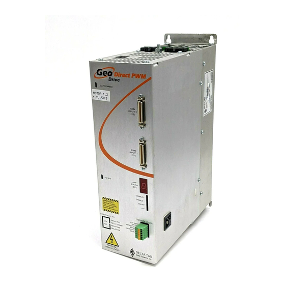
Geo Direct PWM Amplifier
^2
Single Source Machine Control
21314 Lassen St. Chatsworth, CA 91311 // Tel. (818) 998-2095 Fax. (818) 998-7807 //
..............................................................................
^3
Direct PWM Amplifier
^4
500-603700-xIxx
^5
November 15, 2013
Power // Flexibility // Ease of Use
www.deltatau.com
Advertisement
Table of Contents

Related Manuals for Delta Tau Geo Direct PWM Amplifier


Summary of Contents for Delta Tau Geo Direct PWM Amplifier
- Page 1 INSTALLATION MANUAL Geo Direct PWM Amplifier Direct PWM Amplifier 500-603700-xIxx November 15, 2013 ……………………………………………..…...………………. Single Source Machine Control Power // Flexibility // Ease of Use 21314 Lassen St. Chatsworth, CA 91311 // Tel. (818) 998-2095 Fax. (818) 998-7807 // www.deltatau.com...
-
Page 2: Operating Conditions
Copyright Information © 2013 Delta Tau Data Systems, Inc. All rights reserved. This document is furnished for the customers of Delta Tau Data Systems, Inc. Other uses are unauthorized without written permission of Delta Tau Data Systems, Inc. Information contained in this manual may be updated from time-to-time due to product improvements, etc., and may not conform in every respect to former issues. - Page 3 REVISION HISTORY REV. DESCRIPTION DATE CHANGE APPROVAL Added Power On/Off procedures, Power PMAC section, 11/15/2013 Refurbished entire manual...
-
Page 4: Table Of Contents
Geo Direct PWM Amplifier Table of Contents INTRODUCTION ........................6 SPECIFICATIONS ........................7 ..........................7 UMBER ....................7 NVIRONMENTAL PECIFICATIONS .......................8 LECTRICAL PECIFICATIONS 230 VAC Drives – Single Axis ....................8 230 VAC Drives – Dual Axis....................9 480 VAC Drives – Single Axis ....................10 480 VAC Drives –... - Page 5 Geo Direct PWM Amplifier PWM FREQUENCY ......................36 POWER PMAC3 DRIVE SETUP ..................37 ......................37 ARAMETERS ..................... 38 HANNEL ARAMETERS POWER PMAC2 DRIVE SETUP ..................40 ......................40 ARAMETERS ..................... 41 HANNEL ARAMETERS TURBO PMAC2 DRIVE SETUP ................... 43 ......................
-
Page 6: Introduction
They support a wide variety of motors and power ranges. The Geo Direct PWM amplifiers interface directly with Delta Tau’s PMAC2 or PMAC3 style digital ASICs, typically found in the axis expansion cards inside a Turbo or Power UMAC rack. -
Page 7: Specifications
Geo Direct PWM Amplifier SPECIFICATIONS Part Number 0 0 0 0 = No Safety Relay Main AC Voltage Input: 1 = Safety Relay L = 115 - 230 VAC H = 300 - 480 VAC Number of Axes: 1 = Single Axis... -
Page 8: Electrical Specifications
Geo Direct PWM Amplifier Electrical Specifications 230 VAC Drives – Single Axis GxL051 GxL101 GxL151 GxL201 GxL301 Main Input Power -20% – 240 +10% (~87 – 264) Main AC Input [VAC rms] Rated Input Current @ 240VAC 3ɸ [A rms] 13.2... -
Page 9: 230 Vac Drives - Dual Axis
Geo Direct PWM Amplifier 230 VAC Drives – Dual Axis GxL012 GxL032 GxL052 GxL102 GxL152 Main Input Power -20% – 240 +10% (~87 – 264) Main AC Input [VAC rms] Rated Input Current @ 240VAC 3ɸ [A rms] 1.98 3.96 13.2... -
Page 10: 480 Vac Drives - Single Axis
Geo Direct PWM Amplifier 480 VAC Drives – Single Axis GxH051 GxH101 GxH151 GxH201 GxH301 Main Input Power -20% – 480 +10% (~300 – 525) Main AC Input [VAC rms] Rated Input Current [A rms] 13.2 19.8 Frequency [Hz] 50/60 Hz... -
Page 11: 480 Vac Drives - Dual Axis
Geo Direct PWM Amplifier 480 VAC Drives – Dual Axis GxH012 GxH032 GxH052 GxH102 GxH152 Main Input Power -20% – 480 +10% (~300 – 525) Main AC Input [VAC rms] Rated Input Current @ 240VAC 3ɸ [A rms] 1.98 3.96 13.2... -
Page 12: Receiving And Unpacking
Geo Direct PWM Amplifier RECEIVING AND UNPACKING Delta Tau products are thoroughly tested at the factory and carefully packaged for shipment. When the Geo Direct PWM Drive is received, there are several things to be done immediately: Observe the condition of the shipping container and report any damage immediately to the commercial carrier that delivered the drive. -
Page 13: Mounting, Physical Layout
Geo Direct PWM Amplifier MOUNTING, PHYSICAL LAYOUT The location of the Geo Direct PWM Drive is important. Installation should be in an area that is protected from direct sunlight, corrosives, harmful gases or liquids, dust, metallic particles, and other contaminants. Exposure to these can reduce the operating life and degrade performance of the drive. -
Page 14: Gpx012
Geo Direct PWM Amplifier GPx012 Width Height Depth Weight 3.30 in. / 84 mm 11.00 in. / 280 mm 5.80 in. / 147 mm 4.2 lbs / 1.9 kgs Low Profile, Single Width, No Fan MOTOR 2 (J3) MOTOR 1 (J2) -
Page 15: Gpl032
Geo Direct PWM Amplifier GPL032 Width Height Depth Weight 3.30 in./ 84 mm 11.00 in./ 280 mm 8.00 in./ 203 mm 5.4 lbs/ 2.45 kgs Single Width, No Fan MOTOR 2 (J3) MOTOR 1 (J2) EXT SHUNT (J5) REGEN + REGEN - 2.7”... -
Page 16: Gpx 05 X , Gp X 102, Gpl101, Gph032
Geo Direct PWM Amplifier GPx05x, GPx102, GPL101, GPH032 Width Height Depth Weight 3.30 in./ 84 mm 11.00 in./ 280 mm 8.00 in./ 203 mm 5.5 lbs/ 2.5 kgs Single Width with Fan MOTOR 2 (J3) MOTOR 1 (J2) EXT SHUNT (J5) -
Page 17: Gpx201, Gpx301, Gpx152, Gph102
Geo Direct PWM Amplifier GPx201, GPx301, GPx152, GPH102 Width Height Depth Weight 6.50 in./ 165 mm 11.00 in./ 280 mm 8.00 in./ 203 mm 11.5 lbs/ 5.2 kgs Double Width, Two Fans 5.860” (148.844 mm) 10.625” (269.875 mm) 9.875” (250.825 mm) 8”... -
Page 18: Connector Pinouts And Wiring
Geo Direct PWM Amplifier CONNECTOR PINOUTS AND WIRING Installation of electrical control equipment is subject to many regulations including national, state, local, and industry guidelines and rules. General recommendations can be stated but it is important that the installation be carried out in accordance with WARNING all regulations pertaining to the installation. -
Page 19: Recommended Main Bus Power Wiring/Protection
Geo Direct PWM Amplifier AC input wires must be twisted together to eliminate as much noise radiation as possible. Note Recommended Main Bus Power Wiring/Protection Main bus power lines should run in a separate duct (at least 12” or 30 cm away) from and should never be bundled with the I/O signal, communication, or encoder cables. - Page 20 Geo Direct PWM Amplifier Three-Phase Main AC Power Wiring Diagram 3-PHASE TRANSFORMER 110-240 VAC PROTECTION EARTH EMC/EMI MAGNETIC FILTER CONTACTOR Shielded Phase-Phase Twisted Voltage Suppressors Single-Phase Main AC Power Wiring Diagram Single Phase Source 110-240 VAC Neutral Line PROTECTION EARTH...
- Page 21 Geo Direct PWM Amplifier Transformers Y-Y or Y- transformers should be used. Transformers are NOT advised. They try to balance phases dynamically, creating instances of instability in the Geo Direct PWM Drive’s rectifying circuitry. A line reactor should be installed if a transformer or reliable source of power is not available.
-
Page 22: Recommended Bus Power Fuse And Wire Gauge
Geo Direct PWM Amplifier Recommended Bus Power Fuse and Wire Gauge Geo Drive electronics create a DC bus by rectifying the incoming AC lines. The current flow into the drive is not sinusoidal but rather a series of narrow, high-peak pulses. Keep the incoming impedance small so that these current pulses are not hindered. -
Page 23: J4: 24 Vdc Logic Control
Geo Direct PWM Amplifier J4: 24 VDC Logic Control J4 is used to bring the 24VDC logic power into the Geo Direct PWM Drive. This power can remain on, regardless of the main AC/DC bus power input, allowing the digital control electronics to be active while the main motor power control is passive. -
Page 24: J2 - J3: Motor Wiring
Geo Direct PWM Amplifier J2 – J3: Motor Wiring The cable wiring must be shielded and have a separate conductor connecting the motor frame back to the Geo Direct PWM Drive’s chassis. Tie ground and shield to chassis stud J2 – J3: Molex 3-Pin Female... -
Page 25: Motor Cable, Noise Elimination
Geo Direct PWM Amplifier The motor thermostats are brought in through connector X3. Note Motor Cable, Noise Elimination The Geo Direct PWM Drives’ voltage output has a fundamental frequency and amplitude that corresponds to motor speed, torque, and number of poles. The Geo Direct PWM Drive produces higher frequency voltage components corresponding to the rise, fall and repetition rate of the fast switching PWM signals. -
Page 26: Motor Selection
Geo Direct PWM Amplifier Ferrite cores are also commonly used with lower inductance motors to enhance compatibility with the Geo Direct PWM Drive, which is specified to a minimum of 2 mH. Note Do not use a motor wire gauge less than 14 AWG for 5/10A or 8/16A axes, and 10 AWG for 15/30A or 30/60A axes unless otherwise specified by the motor manufacturer. - Page 27 Geo Direct PWM Amplifier Motor Torque Torque requirements in an application can be viewed as both instantaneous and average Typically, the instantaneous or peak torque is the sum of machining, and frictional forces required to accelerate the inertial load. The energy required to accelerate a load follows the equation T=JA where T is the torque, J is the inertia, and A is the acceleration.
-
Page 28: J5: External Shunt Resistor
Geo Direct PWM Amplifier J5: External Shunt Resistor J5 is used to wire an external shunt resistor to expel the excess power during demanding deceleration profiles. These shunt resistors are designed to drain excess bus energy very quickly. All applications using Geo direct PWM Drives (all configurations) are strongly advised to install an external shunt resistor. -
Page 29: Recommended Shunt Resistors
Geo Direct PWM Amplifier The black wires are for the thermostat and the white wires are for the shunt resistor. The shunt resistor incorporates a normally closed (N.C) thermal overload protection thermostat that opens up when the core temperature of the resistor exceeds 225°C (450° F). This thermostat is accessible through the two black leads. -
Page 30: Shunt Resistor Layout
Geo Direct PWM Amplifier Shunt Resistor Layout Connector PinOuts and Wiring... -
Page 31: X1 - X2: Pwm Connectors
Geo Direct PWM Amplifier X1 – X2: PWM Connectors This mini D36 connector provides the interface to the PWM output channel from the controller (PMAC). X1 – X2: 36-Pin Mini-D Connector Pin# Symbol Function Description Notes Reserved Reserved ADC_CLK1+ Command... -
Page 32: X3: Discrete I/Ofor Motor Thermals
Geo Direct PWM Amplifier X3: Discrete I/O for Motor Thermals This 6-pin Phoenix Contact terminal block provides connectivity to low impedance 12 – 24 VDC motor thermostat overload detection. This is a normally closed contact, in normal mode operation the Geo direct PWM Drive expects to see 12 –... -
Page 33: X4: Safety Relay
Geo Direct PWM Amplifier X4: Safety Relay This 4-pin Phoenix Contact Terminal Block provides connectivity to a safety relay input, and If the Safety Relay option is installed, there is a dedicated Safety Input @24VDC (user supplied). When the Safety Input is asserted, then the hardware will cut the 20V power to the gate driver which will prevent all output from the power stage (the Gate Enable LED will turn off). -
Page 34: Power On/Off Procedures
Geo Direct PWM Amplifier POWER ON/OFF PROCEDURES Changing the ADC clock on the controller (PMAC) side requires recycling power on the Geo Direct PWM Drive. Caution Main bus power should NEVER be applied if the 24V logic power is NOT applied. - Page 35 Main bus power should Not be recycled within a time range of about ~ 5 minutes. Caution With the GPx201 and GPx301 models, it is possible to use the external shunt resistor as a bleeding resistor to avoid the downtime delay. Contact Delta Tau for details. Note Power On/Off Procedures...
-
Page 36: Pwm Frequency
Geo Direct PWM Amplifier PWM FREQUENCY The minimum PWM frequency of a system is based on the time constant of the motor. In general, the lower the time constant, the higher the PWM frequency should be. The motor time constant is calculated dividing the motor inductance by the resistance (phase-phase). -
Page 37: Power Pmac3 Drive Setup
Geo Direct PWM Amplifier POWER PMAC3 DRIVE SETUP The ADC Strobe Word, Gate3[i].AdcAmpStrobe, must be set to $FFFFFC for proper operation in default mode. Failure to do so could result in damage to the amplifier. Caution Key Gate Parameters The following Gate-specific parameters are essential for the proper software setup of the Geo Direct... -
Page 38: Key Channel Parameters
Geo Direct PWM Amplifier Key Channel Parameters The following channel-specific parameters are essential for the proper software setup of the Geo Direct PWM Drive: Structure Element Description Typical/Default Notes Gate3[i].Chan[j].PwmFreqMult PWM Frequency 4.5 KHz PWM Motor[x].ServoCtrl Activate channel Motor[x].PhaseCtrl Commutation enable With PackInData = 0 Motor[x].PhaseOffset... - Page 39 Geo Direct PWM Amplifier Trying to enable the Geo Direct PAM Drive with misreported current data could result in damaging the electronics of the Drive. Caution At this point of the drive-motor setup, and before tuning the current loop, a couple of sanity checks can be performed, making sure that: ...
-
Page 40: Power Pmac2 Drive Setup
Geo Direct PWM Amplifier POWER PMAC2 DRIVE SETUP The ADC Strobe Word, Gate1[i].AdcStrobe, must be set to $3FFFFF for proper operation in default mode. Failure to do so could result in damage to the amplifier. Caution Key Gate Parameters The following Gate-specific parameters are essential for the proper software setup of the Geo Direct... -
Page 41: Key Channel Parameters
Geo Direct PWM Amplifier Key Channel Parameters The following channel-specific parameters are essential for the proper software setup of the Geo Direct PWM Drive: Structure Element Description Typical/Default Notes Motor[x].ServoCtrl Activate channel Motor[x].PhaseCtrl Commutation enable Motor[x].PhaseOffset Commutation Phase angle 512 for Brush Motor Motor[x].pAdc... - Page 42 Geo Direct PWM Amplifier Trying to enable the Geo Direct PAM Drive with misreported current data could result in damaging the electronics of the Drive. Caution At this point of the drive-motor setup, and before tuning the current loop, a couple of sanity checks can be performed, making sure that: ...
-
Page 43: Turbo Pmac2 Drive Setup
Geo Direct PWM Amplifier TURBO PMAC2 DRIVE SETUP The ADC Strobe Word, I7m06 ($C014 in Non-Turbo PMAC), must be set to $3FFFFF for proper operation in default mode. Failure to set I7m06 equal to $3FFFFF could result in damage to the amplifier. -
Page 44: Key Channel Parameters
Geo Direct PWM Amplifier Key Channel Parameters The following channel-specific parameters are essential for the proper software setup of the Geo Direct PWM Drive: Variable Description Typical/Default Notes Ixx00 Activate channel Ixx01 Commutation enable Ixx72 Commutation Phase angle 512 for Brush Motor... - Page 45 Geo Direct PWM Amplifier I2T Settings, Ixx57, Ixx58, and Ixx69 Example: #define ServoClk 2.258 ; Servo Clock [KHz]—computed in Dominant Clock Settings Section #define ContCurrent ; Continuous Current Limit [Amps] -User Input #define PeakCurrent ; Instantaneous Current Limit [Amps] -User Input #define MaxADC 16.26...
-
Page 46: Drive Command Structure
Geo Direct PWM Amplifier DRIVE COMMAND STRUCTURE Default Mode In default mode, the Geo Direct PWM Drive returns phases A and B current measurements as well as global and axis faults. Failure to set the ADC strobe word correctly could result in damaging the drive’s electronics. -
Page 47: Enhanced Mode
Geo Direct PWM Amplifier Enhanced Mode Enhanced mode enables access to and control of additional functions: Bus voltage reading IGBT temperature(s) reading Set PWM control for brush motor Turn Line Monitor off The drive must be put in enhanced mode before accessing the additional functions. - Page 48 Geo Direct PWM Amplifier And the data is found in the lower 12 bits of ADC B for each axis: PMAC Type ADC B data register Non-Turbo Y:$C006 Turbo Mxx06 Power PMAC2 Gate1[i].Chan[j].Adc[1] Power PMAC3 Gate3[i].Chan[j].AdcAmp[1] ADC B Data Register...
-
Page 49: Troubleshooting
Geo Direct PWM Amplifier TROUBLESHOOTING LED Status Description Green when axis 1 is enabled ENABLE 1 when axis 1 is not enabled Unlit does not necessarily mean a faulty condition Green when axis 2 is enabled ... -
Page 50: Error Codes
Geo Direct PWM Amplifier Error Codes Display Error / Fault Code Description Description AXIS 1 AXIS 2 Indicates that the I2T model, hard-coded in the Over Current amplifier processor projecting current output over time, has been violated within the operating current specification range of the amplifier. - Page 51 Geo Direct PWM Amplifier Display Error / Fault Troubleshooting Code Description Notes GLOBAL Normal Mode No faults reported Operation The bus voltage has exceeded the permissible threshold: 420 VAC for GPL Drives Over 820 VAC for GPH Drives Voltage ...
-
Page 52: Appendix A: Cable/Connector Kits
Geo Direct PWM Amplifier APPENDIX A: CABLE/CONNECTOR KITS PWM Cables Option Cable Length Part Number 24” (600 mm) CABPWM-1 200-602739-024X 36” (900 mm) CABPWM-2 200-602739-036x 60” (1.5 m) CABPWM-3 200-602739-060x 72” (1.8 m) CABPWM-4 200-602739-072x 84” (2.1 m) CABPWM-5 200-602739-084x 144”... -
Page 53: Cable Kits
Geo Direct PWM Amplifier Cable Kits Part Number Model Description Gxx012xx Molex mating connectors pre-crimped for 2 axes: Gxx032xx 3 ft. AC Input Cable CABKIT1B Gxx052xx 3 ft. 24 VDC Power Cable GxL102xx 10 ft. shielded Motor Cables Molex mating connectors pre-crimped for 1 axis: ...
Need help?
Do you have a question about the Geo Direct PWM Amplifier and is the answer not in the manual?
Questions and answers