Table of Contents
Advertisement
Quick Links
Download this manual
See also:
User Manual
Advertisement
Table of Contents

Related Manuals for Sony Vaio PCG-F650


Summary of Contents for Sony Vaio PCG-F650
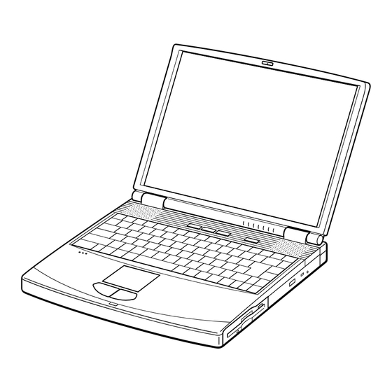
- Page 1 PCG-F650/F680/F690 SERVICE MANUAL US Model Canadian Model S400 Illust : PCG-F690 NOTEBOOK COMPUTER 9-872-148-11...
- Page 2 Caution Markings for Lithium/Ion Battery - The following or similar texts shall be provided on battery pack of equipment or in both the Sony and VAIO are trademarks of Sony. Intel logo and Intel Inside operating and the service instructions.
-
Page 3: Table Of Contents
TABLE OF CONTENTS Section Title Page Section Title Page CHAPTER 1. REMOVAL CHAPTER 2. SELF DIAGNOSTICS 1-1. Flowchart ................. 1-1 2-1. Required Tools and Peripheral Devices ......2-1 1-2. Main Electrical Parts Location Diagram ......1-1 2-2. Tools and Peripheral Device Connection ......2-3 1-3. -
Page 4: Chapter 1. Removal
CHAPTER 1. REMOVAL 1-1. Flowchart BEZEL DISPLAY INVERTER HOUSING HOUSING UNIT ASSY ASSY ASSY ∗P 1-7 ∗P 1-7 ∗P 1-8 〈 P 1-12 〉 (P 1-9) (P 1-9) (P 1-10) 〈 P 1-11 〉 〈 P 1-12 〉 〈 P 1-12 〉 HOOD POWER DVD-ROM... -
Page 5: Hinge Cover
1-3.Removal 1. Hinge Cover 2Hinge Cover 1Door I/O 2Hinge Cover 2. Keyboard Unit, Palm Rest Assy, Hood Keyboard Assy, Touch Pad, CNX-82 Board 1M2X4 Special Head 2Pull it up sliding it to the right. 3M2X4 Special Head Keyboard Unit Hood Keyboard Assy 6+B 2X18 7Pull it to the front slightly and raise to remove it. -
Page 6: Display Assy, Dvd-Rom Drive
3. Display Assy, DVD-ROM Drive 7M2X6 Special Head Display Assy (X2) 8M2X6 Special Head 8M2X6 Special Head 4M2X4 Special Head (X2) 5GND Plate Hinge 6M2.6 Cross (Hole) Bind 6M2.6 Cross (X2) (Hole) Bind 1Screw (M2), 0 Number P3 Kind 6M2.6 Cross (Hole) Bind (X2) DVD-ROM Drive 2M2X4 Special Head 4. -
Page 7: Swx-65 Board, Latch Detector Unit, Pws-12 Board, Nickel Hydrogen Battery
5. SWX-65 Board, Latch Detector Unit, PWS-12 Board, Nickel Hydrogen Battery PWS-12 Board CN6006 3M2X4 Special Head (X3) 1M2X4 Special Head 4PWS-12 Board PWS-12 Board CN6001 2Latch Detector Unit SWX-65 Board CN5101 2SWX-65 Board 5Nickel Hydrogen Battery 6. PC Card Connector, IFX-100 Board, P3 Assy (CPU Module), MBX-41 Board 0+PS 2X4 (X3) P3 Assy 1M2X6 Special Head(X4) -
Page 8: Speaker Unit, Swx-39 Board
7. Speaker Unit, SWX-39 Board 3M2X4 (X2) 2M2X4 (X7) SWX-39 Board Speaker Unit CN301 SWX-39 Board CN302 SWX-39 Board 3M2X4 (X2) SWX-39 Board CN303 Speaker Unit Hood Keyboard 8. SO-DIMM 1M2X4 Special Head 2DIMM Door Removal of SO-DIMM a → b Confidential PCG-F650/F680/F690 (UC) -
Page 9: Attaching The Thermal Sheet
9. Attaching the Thermal Sheet Attach the thermal sheet (20 × 11 mm) to the heat sink of the P3 assembly (CPU module) to be used with the computer. Because the heat dissipation effect of the thermal sheet (thermal conductivity sheet) changes depending on the position where it is attached, prepare the following [Thermal sheet attachment tool] to attach the thermal sheet. -
Page 10: Lcd Section (F690 Model) - Made By Hi
10. LCD Section (F690 Model) – Made by HI – 1. Bezel Housing Assy, LCD Unit (15 inch) 2M2X3 Special Head (X3) 1Side (15) Screw Cover (X3) Bezel Housing Assy 3Cover Screw Shaft 4+P 2.6X6 : claw part Lock Precision Type3 2M2X3 Special Head (X3) 3Cover Screw... -
Page 11: Inverter Assy, Lcd Harness, Fpc
2. Inverter Assy, LCD Harness, FPC LCD Harness 2M2X4 4M2X4 Special Head Special Head Inverter Bracket Inverter Inverter Assy Assy CN1 Display Housing Assy : claw part Confidential PCG-F650/F680/F690 (UC) -
Page 12: Lcd Section (F680 Model) - Made By Sa
11. LCD Section (F680 Model) – Made by SA – 1. Bezel Housing Assy, LCD Unit (15 inch) 1Side (15) Screw Cover (X3) 2+P M2X3 (X3) 3Cover Screw Shaft Bezel Housing Assy 4+P 2.6X6 Lock Precision Type3 : claw part 3Cover Screw 2+P M2X3 (X3) Shaft... -
Page 13: Inverter Assy, Lcd Harness, Fpc, Display Housing Assy
2. Inverter Assy, LCD Harness, FPC, Display Housing Assy Inverter Bracket Harness 2M2X4 4M2X4 Special Head Special Head (X2) Inverter Bracket LCD FPC Inverter Assy Inverter Assy Display Housing Assy Confidential PCG-F650/F680/F690 (UC) 1-10... -
Page 14: Lcd Section (F650 Model) - Made By Sa
12. LCD Section (F650 Model) – Made by SA– 1. Bezel Housing Assy 1Cover Screw Lower 2M2X4 Special : claw part Head (X2) 1Cover Screw Upper 2M2X4 Special Head (X2) Bezel Housing Assy 4M2X4 Special Head (X5) 4M2X4 Special Head (X5) How to release the claw a LCD Unit Bezel Housing Assy... -
Page 15: Lcd Harness, Bracket Lcd Left, Bracket Lcd Right, Lcd Unit (14 Inch)
2. LCD Harness, Bracket LCD Left, Bracket LCD Right, LCD Unit (14 inch) 1+P M2x3 Lock (X4) LCD Unit 1+P M2x3 Lock (X4) Bracket LCD Left LCD Harness Bracket LCD Right 3. FPC, Inverter Assy, Display Housing Assy 2M2X4 Special Head 3M2X4 Special Head Inverter Assy Display Housing Assy... -
Page 16: Using Common Flexible Boards And Dedicated Flexible Boards Differently As Specified
1-4. Using Common Flexible Boards and Dedicated Flexible Boards Differently As Specified When maintaining the VAIO Note F series computer, use the common flexible board and dedicated flexible board differently depending on the type of LCD as follows. When using the common flexible board for maintenance, the flexible board ID portion of the common board must be cut locally using a cutting knife in order to register the ID No. - Page 17 3 Fold the creased portions (recessed portions) of the flexible board in alphabetical order A→B→C→D as shown. (Peak fold by 90 degrees) (Valley fold) (Valley fold) (Valley fold by 90 degrees) NOTE: • The F650 model is shown as an example. However, direction and order of folding remain the same in the F680 model. •...
- Page 18 (Cross-section) 6 Align the LED illumination block with the indicator window. claws Attach the LED illumination block while aligning the notch of the FPC with the claw. LED illumination block claws Display Inverter Assy Housing Assy Indicator window LED illumination Display Housing Assy block (F650 Model)
- Page 19 (F650 Model) Firamen tape (Adhesive tape for fixing and protection) Display Housing Assy 0 Attach the Firamen tape while pressing the star mark " " portion of the FPC. Firamen tape GND Tape (LCD) 9 Peel off the exfoliation tape of the GND 20 to 30mm Tape (LCD) and attach the FPC on the Display Housing Assy...
- Page 20 (F650 Model) LCD Unit (rear side) Terminal side LCD Harness LCD Unit (rear side) LCD Harness (F690/F680 Model) Terminal side qd Attach the LCD Unit to the Display Housing Assy. LCD Harness (Refer to section "1-3. Removal".) Terminal side LCD Unit Display Housing Assy Confidential 1-17...
-
Page 21: Chapter 2. Self Diagnostics
CHAPTER 2. SELF DIAGNOSTICS 2-1. Required Tools and Peripheral Devices Tools and Peripheral Devices Test Items Serial Loopback Tool Serial Port (COM) test Specified Loopback Tool (Refer to next page.) Parallel Loopback Tool Parallel Port (printer) test Specified Loopback Tool (Refer to next page.) V.34 Modem and Line Simulator Modem test PC Card Tester... - Page 22 [Reference] On Serial/Parallel Loopback Tool • The serial loopback tool and the parallel loopback tool are necessary for diagnostics of the serial communication line and the parallel communication line. Fabricate the serial loopback tool and the parallel loopback tool locally referring to the connection diagrams shown below.
-
Page 23: Tools And Peripheral Device Connection
2-2. Tools and Peripheral Device Connection System Connection Diagram 2Parallel 1Serial loopback tool loopback tool Serial I/F Serial Parallel output output Modem 5,qsPCG-N505, XR series 3Transmission line simulator IrDA PPK Button send/ receive Power SW Phone jack CD-ROM 4PC card tester 9Diagnostics CD-ROM media 8Diagnostics... -
Page 24: Starting Up The Service Diagnostics
2-3. Starting up the Service Diagnostics 1. The service diagnostics floppy disk and CD disc are prepared for the respective models separately. Insert the service diagnostics floppy disk and CD disc of the desired model, then turn on the main power of the personal computer. Reads automatically the model information stored in the CD-ROM and displays the test menu. - Page 25 • HDD test... Tests whether the HDD returns a response when communication is established with the hard disk drive. The HDD can be tested without damaging the HDD data (without formatting the HDD) in this test since the HDD data is tentatively stored in memory during the test.
- Page 26 • Touch pad test... Tests the touch pad. Tests whether the cursor moves, and whether right-clicking and left-clicking function properly. The dialog box appears three times. Move the cursor to the box that appears. The tests are performed in the following order. (1) Touch pad (2) Left-click button (3) Right-click button (Two times)
- Page 27 • IrDA test... Performs the IrDA communication test. Another personal computer to communicate with is necessary for this test. The models released from the year 2000 have already been confirmed that they do not cause any problems regarding the IrDA communication.
-
Page 28: Inspecting Windows
2-5. Inspecting Windows The Windows inspection contains the following two types of inspection. Audio Modem Before starting inspections, create a floppy disk from the service diag CD to be serviced. The files to be used for inspection are stored in the following sub directory inside the CD. Copy all the files in the folder to the floppy disk. -
Page 29: Chapter 3. Block Diagram
33MHz CLK GEN PCI BUS 14MHz C9716 Serial DSUB-9 USB 0 PIRQD* 100-pin PIRQC* PORT0 i.LINK Audio PIRQD* (USB) SONY YAMAHA Parallel IFX-100 CXD3222AR YMF744B DS-1S DSUB-25 FUJI MODEM USB 1 Dev# 8 MD8405E South Bridge Dev# 9 CONEXANT PORT1... -
Page 30: Chapter 4. Frame Harness Diagram
CHAPTER 4. FRAME HARNESS DIAGRAM CNX-82 CNX-82 Side-B Side-B NICKEL HYDROGEN NICKEL HYDROGEN CN201 CN201 CN202 CN202 BATTERY BATTERY PWS-12 SWX-65 Side-A P3 ASSY CN6001 PC 100 SO-DIMM MODULE CN5101 CN5101 CN6006 CN6005 BATTERY CN 151 DIMM TOUCH TOUCH CN6003 PACK FDD BAY Side-A... -
Page 31: Chapter 5. Exploded Views And Parts List
CHAPTER 5. EXPLODED VIEWS AND PARTS LIST NOTE: The components identified by mark 0 or • The mechanical parts with no reference number in the dotted line with mark 0 are critical for safety. exploded views are not supplied. Replace only with part number specified. •... -
Page 32: Main Section
5-1. Main Section Ref.No. Part No. Description Ref.No. Part No. Description X-4622-818-1 ASSY BOTTOM (A) * 71 4-641-851-02 SPRING (FDD), PLATE 4-640-837-12 DOOR BATTERY * 72 4-644-337-02 BRACKET I/O A-8066-180-A COMPLETE PWB RO-44 1-756-038-11 BATTERY, NICKEL HYDROGEN 4-644-346-02 HEATSINK BOTTOM 4-644-358-11 DOOR DIMM * 11 4-644-348-01 INSULATOR HEATSINK BOTTOM... - Page 33 (F650 Model) Ref.No. Part No. Description 4-641-726-41 SCREW (M2), SPECIAL HEAD 4-644-518-01 SCREW (M2X18), +B 4-644-899-01 SCREW (M2), 0 NUMBER P3 KIND 4-639-112-01 SCREW M2X4 4-644-402-02 SCREW (MBX) 4-646-807-01 0 PLATE M2.5 (FDD) 4-644-402-12 SCREW (MBX) 4-641-726-11 SCREW (M2), SPECIAL HEAD 4-640-694-41 BOLT (M2), SPRING 7-685-106-19 SCREW +P 2X10 TYPE2 NON-SLI 7-628-253-00 SCREW +PS 2X4...
-
Page 34: Lcd Section (F690 Model) - Made By Hi
5-2. LCD Section (F690 Model) – Made by HI – Ref.No. Part No. Description Ref.No. Part No. Description 1-475-809-31 INVERTER UNIT 4-641-726-41 SCREW (M2), SPECIAL HEAD X-4622-447-4 HINGE LEFT 15G 4-641-726-11 SCREW (M2), SPECIAL HEAD X-4622-793-1 ASSY HOU, BEZEL 15SX 4-641-726-81 SCREW (M2), SPECIAL HEAD 4-637-902-31 LATCH 4-644-165-01 SCREW (M2.6X4), 0 PLATE P1 MAIN... -
Page 35: Lcd Section (F680 Model) - Made By Sa
5-3. LCD Section (F680 Model) – Made by SA – Ref.No. Part No. Description Ref.No. Part No. Description 1-475-809-31 INVERTER UNIT 4-641-726-41 SCREW (M2), SPECIAL HEAD X-4622-447-4 HINGE LEFT 15G 4-641-726-11 SCREW (M2), SPECIAL HEAD X-4622-416-4 ASSY HOU, BEZEL 15X (UC) 4-642-761-01 +P M2X3 LOCK 4-637-902-41 LATCH 4-644-165-01 SCREW (M2.6X4), 0 PLATE P1 MAIN... -
Page 36: Lcd Section (F650 Model) - Made By Sa
5-4. LCD Section (F650 Model) – Made by SA – Ref.No. Part No. Description Ref.No. Part No. Description 1-418-578-13 INVERTER UNIT ACCESSORIES X-4622-486-3 HINGE LEFT 14G (SA) ************ X-4622-431-1 ASSY HOU, BEZEL 14 (SA) 0701 4-635-277-11 COVER SCREW LOWER 1-782-614-11 CORD, POWER 4-635-276-11 COVER SCREW UPPER A-8046-136-A ASSY WEIGHT SAVER (NHA) 0703... - Page 37 PCG-F650/F680/F690 (UC) This manual and the constituent data may not be replicated, copied nor reprinted in whole or in part without prior written authorization of Sony Corporation. English Sony Corporation 2000I1600-1 Printed in xxx 9-872-148-11 © 2000 Sony Corporation — ? —...
Need help?
Do you have a question about the Vaio PCG-F650 and is the answer not in the manual?
Questions and answers