Table of Contents
Advertisement
Advertisement
Table of Contents

Related Manuals for Brusa BDC546-B


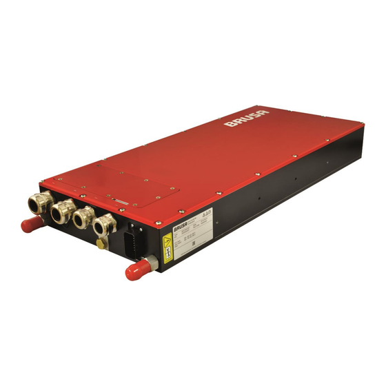
Summary of Contents for Brusa BDC546-B
-
Page 1: Version 1.1
BDC546-B Operating instructions Version 1.1... -
Page 2: Document Version
Document version Version Date Name Comment 18.12.2012 M.Haller Document released 05.01.2015 J. Pitschi - Update of some descriptions of CAN-signals. - Update of value for the current regulators based on tolerances of the internal current measurement. -
Page 3: Table Of Contents
Inhalt Version 1.1 ..............................1 Document version ............................... 2 Introduction ................................. 4 List of abbreviations ............................4 Valid regulator-values ............................. 4 UHS-main-regulator ............................5 Interpretation of the internal current measurement .................... 5 Boostmode ..............................5 Buckmode ............................... 5 Limit regulators ............................... 5 Regulator priorities ............................ -
Page 4: Introduction
Introduction This document has to be read before startup the device first time. Otherwise damage on the device and external connected devices can occur. The signal names in squared brackets ([ ]) are the references to the CAN-matrix. List of abbreviations ... -
Page 5: Uhs-Main-Regulator
UHS-main-regulator The main-regulator regulates the high-side-voltage. For a functional operation, the following CAN-messages have to be set correctly: [SG_Sollwert]: Value of the commanded high-side voltage. (Sollwert engl.: desired value) [SG_HR_Mode_Check]: Interpretation of the internal current measurement Boostmode Direction of current from LS to HS. ... -
Page 6: Regulator Priorities
Due to measurement tolerances a parametrization of the current regulators to zero in order to avoid a change of operating direction may cause problems (especially at no load conditions). Therefore BRUSA recommends to set the current regulators to MIN_CURRENT_LIM, whereby |MIN_CURRENT_LIM| ≥ 2A. -
Page 7: Recommended Bdc-Settings For A Test Assembly
Recommended BDC-settings for a test assembly BDC_2 BDC_1 BDC546 BDC546 UHS_COM active ILS_MIN active Fuel Cell Low-Side (LS) High-Side (HS) High-Side (HS) Low-Side (LS) Battery ULS1 ULS2 UHS_MAX [SG_UHS_max] ULS_MAX [SG_ULS_max] ULS_MAX [SG_ULS_max] UHS_MAX [SG_UHS_max] IHS_MAX ILS_MAX [SG_ILS_max] ILS_MAX [SG_ILS_max] IHS_MAX [SG_IHS_max] [SG_IHS_max] UHS_COM [SG_Sollwert]... -
Page 8: Recommended Bdc-Settings For Operation "Battery To Fuel Cell
Recommended BDC-settings for operation “battery to fuel cell”: BDC_2: UHS_COM_2 > 170V ILS_MAX_2 > |ILS_MIN_1| ILS_MIN_2 = -2 (prevention of boostmode) IHS_MAX_2 > |IHS_MIN_1| (Recommendation: IHS_MAX_2 > ILS_MAX_2) IHS_MIN_2 = -2 (prevention of boostmode) BDC_1: ... -
Page 9: Examples Of Critical Operating States
Examples of critical operating states The following examples shows critical operating states who can occur due to regulator priorities. The examples refer to schematic diagram below. BDC546 UHS_COM active Low-Side (LS) High-Side (HS) Battery 1 Battery 2 UHS_MAX [SG_UHS_max] ULS_MAX [SG_ULS_max] ILS_MAX [SG_ILS_max] IHS_MAX [SG_IHS_max] UHS_COM [SG_Sollwert]... -
Page 10: Condition Uhs_Com < Uhs_Min
Condition UHS_COM < UHS_MIN Device in boostmode: BDC regulates UHS_MIN. Device in buckmode: BDC regulates UHS_COM till UHS < UHS_MIN. Then the BDC regulates on UHS_MIN as well. Condition UHS_COM > UHS_MAX Device in buckmode: BDC regulates UHS_MAX. ... -
Page 11: Other Important Can-Signals
Other important CAN-signals [SG_DigOut_Activate]: Activ high sets AMP_PIN17 to LV_BUS+ (+12V) = 4A (120ms) peak = 200mA cont. [SG_Activate]: Activ high, device starts to work (if there is no error). [BDC_Ready]: Information if the device is ready or not. [BDC_Running]: Information if the device is running or not.
Need help?
Do you have a question about the BDC546-B and is the answer not in the manual?
Questions and answers