
Related Manuals for Brusa BSC624-12V-B Series


Summary of Contents for Brusa BSC624-12V-B Series
- Page 1 TECHNICAL INFORMATION AND START-UP DC/DC converter BSC624-12V-B Translation of the original German operating instructions BRUSA Elektronik AG Neudorf 14 CH–9466 Sennwald +41 81 758 19 00 www.brusa.biz info@brusa.biz...
- Page 2 The content of this document may not be passed on to third parties without the written authorisation of the company BRUSA Elektronik AG - not even in extracts. All technical information, drawings and photos used in this document are protected by copyright and any infringement constitutes a...
- Page 3 ALIDITY This manual is only valid for the devices listed in the following table: BSC624-12V-B01 BSC624-12V-B02 BSC624-12V-B03 BSC624-12V-B04 BSC624-12V-B05 BSC624-12V-B06 BSC624-12V-B07 The decoding of the device designation is as follows: Technical information and start-up BSC624-12V-B...
-
Page 4: Table Of Contents
TABLE OF CONTENTS Foreword ..........................7 List of abbreviations ......................7 Safety and warning instructions ..................8 Symbols and their meaning ......................8 Safety instructions and danger levels ..................9 Generally applicable safety measures ..................10 3.3.1 Safety instructions for cooling water systems ..............10 3.3.2 Safety instructions for mechanical systems ............... - Page 5 Technical properties ......................... 25 Block diagram BSC624-12V-B ....................25 Basic function / EMC concept ....................26 6.4.1 Topology benefits ......................26 6.4.2 Internal current supplies ....................27 6.4.3 LV filter concept ........................ 28 6.4.4 HV filter concept ........................ 29 6.4.5 AUX filter concept ......................
- Page 6 Control connector ........................51 HV power connector ......................... 52 LV power connector ......................... 53 LV- / PGND (power ground) ..................... 54 Cooling system ......................... 55 Installation / initial start-up ....................56 Producing the cable glands for the HV power connector ............59 Ventilating the cooling system ....................
-
Page 7: Foreword
Foreword Dear customer With the BRUSA BSC624-12V-B, you have purchased a very high performance and versatile product. As the present device is a high-performance electronics product which uses dangerous voltages and currents, special expertise in handling and operation are required! Before installing the device or carrying out any other work on it, this manual –... -
Page 8: Safety And Warning Instructions
Safety and warning instructions In this chapter, you will find safety instructions applying to this device. These instructions refer to the assembly, start-up and the running operation in the vehicle. Always read and observe these instructions in order to protect people's safety and lives and to avoid damage to the device! Symbols and their meaning Throughout this manual, some specific technical symbols are used. -
Page 9: Safety Instructions And Danger Levels
Safety instructions and danger levels DANGER This instruction warns about severe irreversible risks of personal injury with fatal consequences. Avoid this risk by adhering to this instruction! WARNING This instruction warns about the risk of severe but reversible injury! Avoid this risk by adhering to this instruction! CAUTION This instruction warns about a minor risk of injury! Avoid this risk by adhering to this instruction! -
Page 10: Generally Applicable Safety Measures
Generally applicable safety measures The following safety measures have been developed based on the knowledge of the manufacturer. They are incomplete as they can be supplemented by local and/or country-specific safety instructions and guidelines for accident prevention. The system integrator and/or distributor of the device must therefore supplement the present general safety instructions by country-specific and local guidelines. -
Page 11: Safety Instructions For Handling And Operation
In the case of any fluid ingress, do not start the device and immediately contact the company BRUSA Elektronik AG. Always use an insulation monitoring unit to continuously monitor the galvanic isolation between the HV and LV circuit! ... -
Page 12: Safety Instructions For Electrical Systems
3.3.4 Safety instructions for electrical systems DANGER High voltage! Danger to life! Never touch the HV wires or HV connections without ensuring the absence of voltage beforehand! The device may only be connected by a qualified electrician! Safety installations must never be by-passed or circumvented! Any resulting malfunctions could have life threatening consequences! INSTRUCTION Never open the device without authorisation! The opening of the device (sealed housing) directly... -
Page 13: Safety Installations / Power Limitations
HV components in the vehicle. The interlock signal must be generated and analysed respectively via an upstream control unit (e.g. BRUSA PDU254). Further information on the interlock can be found in chapter 7.1.10 Pin 19 IL1, pin 20 IL2... -
Page 14: Overload Protection - Derating
3.4.3 Overload protection – derating This safety installation is a self-protection feature of the DC/DC converter. If the device reaches a defined temperature threshold, this reduces the power rating (derating) to protect the device from damage caused by overheating. Consequently, the maximum possible current is reduced proportionally to the temperature increase in order to avoid a further rise in the temperature. -
Page 15: Hv - Overvoltage Shut-Down
Windings of the HF power transformers If the temperature at the windings of the HF power transformers reaches >/= 106°C, the current is reduced successively to a temperature value of < 131°C. At >/= 131°C, the device shuts down. ... -
Page 16: Lv - Overvoltage Shut-Down
3.4.5 LV – Overvoltage shut-down The device provides the following possibilities for identifying an overvoltage at the LV side: Rapid HW overvoltage identification (immediate shut-down of the device if voltage > 20 V) Slow SW overvoltage identification (shut-down of the device if voltage > 16.4 V; automatic reactivation if voltage <... -
Page 17: Requirements To The Start-Up Personnel
Requirements to the start-up personnel All courses of action described in this manual may only be carried out by a qualified electrician! Specialist staffs are defined as electricians with professional training, knowledge and experience in the field of high voltage electronics / electric mobility, ... -
Page 18: General
Furthermore, it contains technical data, application information and a basic description of the device and its specific components. The operational and safety instructions given are to be adhered to in order to ensure the ongoing optimum functioning of the device and to meet the warranty requirements of BRUSA Elektronik AG. Scope of the entire documentation INFORMATION To commission the device successfully, the entire documentation as well as diverse software are required. -
Page 19: Scope Of Delivery
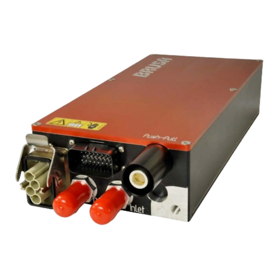
Scope of delivery Meaning Pieces Illustration 1. DC/DC converter BSC624-12V-B 2. 23 pole control connector with crimp contacts * AMPSEAL 770680-1 3. SN/LP contacts AMPSEAL 770854-1 for wire diameter: 0.5 mm 4. Harting high voltage connector set HAN-Modular Compact: * ... -
Page 20: Applicable Standards
This manual has been produced under application and consideration of the EC guidelines, national laws and harmonised standards (EN) valid at the time of production and relevant to the product BSC624-12V-B. Contact information of the manufacturer BRUSA Elektronik AG Neudorf 14 9466 Sennwald... -
Page 21: Use And Limits Of The Product
Use and limits of the product Proper use The product BSC624-12V-B has been designed to supply the 12 V wiring system in the applications listed below, taking into consideration the limits indicated in chapter Integration in hybrid vehicles Integration in electric vehicles ... -
Page 22: About This Device
About this device Technical data High voltage side Remarks BSC624-12V-B Unit Min. voltage, limited power = 14 V LVmax Min. voltage, full power Max. voltage, full power Overvoltage, deactivation of the power stage > 470 Max. voltage, no operation, max. 1 min Device may be damaged With reverse polarity Fuse triggers... - Page 23 Galvanic isolation Remarks BSC624-12V-B Unit Withstand voltage between HV and LV Test voltage 2’700 Galvanic isolation between signal and power ground Test voltage Isolation resistance HV-side against chassis/GND > 5 MΩ Control circuit Remarks BSC624-12V-B Unit Min. voltage for signals at the control connector (AUX) Max.
- Page 24 Level of efficiency Remarks BSC624-12V-B Unit Typical = 330V, U = 14.0V, I = 150A 94.4 Basic mechanical data Remarks BSC624-12V-B Unit Housing material Corrosion-tight aluminium AlMgSi1 Length Width Height Housing volume Without connector 3.15 Weight (without cooling water) +/- 0.05kg IP protection IP65 External diameter of cooling water connection pieces -...
-
Page 25: Technical Properties
Technical properties Compact and light-weight construction Vibration-resistant construction for mobile usage Coverage of a large HV range (220 – 450 V Bi-directional functioning All connections are pluggable (excluding LV negative pole) Excellent EMC properties ... -
Page 26: Basic Function / Emc Concept
Basic function / EMC concept The BSC624-12V is a bi-directional DC/DC converter with galvanic isolation between the high voltage and the low voltage circuit. The device is based on a transformer stage working in a serial-resonant manner, by means of which the galvanic isolation is realised. -
Page 27: Internal Current Supplies
6.4.2 Internal current supplies Generally, the device can be supplied by HV as well as via pin 2 AUX. For the full operational availability, however, the 12.5 V / 2.5 A supply must be active. This supply starts automatically at a HV voltage of > 75 V. Due to the greater output voltage, the 11.3 V / 1 A supply of pin 2 AUX is deactivated automatically in order to reduce the current consumption from the wiring system. -
Page 28: Lv Filter Concept
6.4.3 LV filter concept Component Value Unit 680.0 µF 40.0 µF 364.0 130.0 µF 816.0 µF 17.6 µF 1‘683.6 µF total The capacitors E and E are implemented as SMD tantalum capacitors in order to achieve the respective capacity values required. ... -
Page 29: Hv Filter Concept
6.4.4 HV filter concept Component Value Unit 2314.0 µH µH 15.0 16.2 µF The HV choke located at the input is generally of the common-mode choke type (L ). However, it also helps to filter the differential mode interferences by means of the existing leakage inductance (L ... -
Page 30: Aux Filter Concept
6.4.5 AUX filter concept In order to achieve an ideal cushioning of the line-bound interferences, all pins of the control connector are filtered to GND by means of SMD capacitors. GND, on the other hand, is connected to the housing with very low impedance. -
Page 31: Warnings On The Device
Warning signs are installed on the device to warn the operator of possible dangers. Should one of these warning signs be missing or become illegible due to wear and tear, it is to be renewed immediately. In order to obtain an original label, please refer to the BRUSA support at the manufacturer's address indicated in chapter Technical information... -
Page 32: Vehicle Installation Basic Principle
Vehicle installation basic principle Technical information and start-up BSC624-12V-B... -
Page 33: Safety Concept Vehicle Installation
Safety concept vehicle installation INFORMATION This safety concept is a recommendation of BRUSA Elektronik AG and is a general requirement for the safe operation of electric vehicles! 6.7.1 Principle of operation Interlock The interlock switch (1) is closed if the corresponding interlock condition of each devices is met (closed service cover, plugged HV connections ...). -
Page 34: Overview Of The Main Structural Components
Overview of the main structural components HV warning sign Control connector Housing cover Housing Water duct cover LV negative pole Pressure compensation membrane LV positive pole Cooling water connections HV power connector Technical information and start-up BSC624-12V-B... -
Page 35: Dimensions And Installation Information
Dimensions and installation information For the installation of the device, the following points must be generally adhered to: Despite the existing IP protection, the device should only be exposed to environmental influences to the extent required by the application. ... -
Page 36: Dimensions
6.9.2 Dimensions 6.9.3 Installation position Generally, no special installation position for the device is prescribed as the internal components are mounted in a vibration-resistant manner. However, the following installation positions are NOT allowed: Connector side to the top: This causes the danger of condensate accumulation on the connectors, which in turn increases the risk of corrosion. - Page 37 6.10 Type plate Classification Serial number Date of production Product number (specified by the customer) Supplier number (specified by the customer) HV voltage range for operation Level of efficiency Max. admissible cooling water temperature at the input LV voltage range for operation LV peak current Peak power, buck mode IP protection class...
-
Page 38: Electrical Interfaces
Electrical interfaces Control connector LV power connector Chap.7.1 Pin assignment of control connector Chap. 7.3 Pin assignment of LV power connector (device side) (device side) LV- / PGND (power ground) HV power connector Chap. 8.4 LV- / PGND (power ground) Chap. -
Page 39: Pin Assignment Of Control Connector (Device Side)
Pin assignment of control connector (device side) INSTRUCTION Information on the pins required and / or recommended for operation or necessary for programming can be found in chapter 8.1 Control connector 2. AUX Signal ground +12V (Minus wiring system, terminal 31) (Plus wiring system, terminal 30) 4. -
Page 40: Pin 1 Gnd
7.1.1 Pin 1 GND INFORMATION If control signals of the device are connected with other vehicle components, the vehicle's ground is to be connected at this pin. Internal wiring Pin 1 GND housing Direct connection to the ground of the control unit. ... -
Page 41: Pin 2 Aux
7.1.2 Pin 2 AUX Internal wiring 12.5V 10.7V 12.5V- Supply Supply Pin 2 100uH 1.5A 11.3V Supply Supply If no voltage is present at the HV power connector, the device is supplied via this pin by the 12 V wiring system. -
Page 42: Pin 3 En
7.1.3 Pin 3 EN INFORMATION The admissible voltage range for pin 3 EN = high is 7 - 32 V. For a pin 3 EN = low, a voltage of < 1 V is required. Internal wiring To programme a new firmware, pin 13 must be PRO = high. For this purpose, it is not necessary that pin 3 is EN = high. -
Page 43: Pin 4 Do0 - Pin 7 Do3
7.1.4 Pin 4 DO0 – pin 7 DO3 INFORMATION These digital outputs all have the following characteristics: = 1.7 Ω at T R = 25°C DSON V = 32 V OUTmax ≥ 45 V (voltage resistance for inductive loads) ... -
Page 44: Pin 8 Pg1, Pin 14 Pg2, Pin
Both pins are isolated from the GND ground and the remaining control signals (avoiding disturbances caused by stray voltage). Via the CAN interface, messages can be transmitted in accordance with the CAN matrix provided by BRUSA as .dbc-file. -
Page 45: Pin 11 Txd, Pin 12 Rxd
100Ω 200Ω The firmware for the microprocessor can be downloaded via this interface (provided by BRUSA). Pin 13 PRO must be high for this. CAN parameters and current operating data, such as voltages, currents and temperatures of the device, can be read out and displayed via this interface. -
Page 46: Pin 13 Pro
INSTRUCTION The programming of an incorrect firmware may damage the device! Therefore, the programming may only be carried out after consultation with BRUSA Elektronik AG! INFORMATION This pin is only activated for the programming of a new firmware (pin 13 PRO = high). For this purpose, pin 3 EN must not be high. -
Page 47: Pin 19 Il1, Pin 20 Il2
7.1.10 Pin 19 IL1, pin 20 IL2 INSTRUCTION In order to guarantee the functioning of the interlock, the signal of the internal interlock identification in the HV connector may not be modified or distorted! INFORMATION The interlock is a safety-relevant function, which is processed internally but can also be analysed via an upstream system (e.g.: vehicle system). - Page 48 by the internal or external identification. The LV connector is not integrated into the interlock circuit. For the wire bridge in the HV customer side connector the delivered wire has to be installed. The installed wire bridge may not be removed or modified (e.g. extended)! ...
-
Page 49: Pin 21 Ai1, Pin 22 Ai2, Pin 23 Ai3
7.1.11 Pin 21 AI1, pin 22 AI2, pin 23 AI3 INFORMATION Via these three analogue inputs, two different functions each can be realised optionally: 1 mA – current supply for external 5 kΩ potentiometer 33 kΩ pull-up resistor for external 33 kΩ NTC temperature sensor. Internal wiring Analog Pin 21 AI1... -
Page 50: Pin Assignment Of Hv Power Connector (Device Side)
Pin assignment of HV power connector (device side) HV interlock loop input HV interlock loop output HV+ (high voltage Plus) HV- (high voltage Minus) Information on the interlock function can be found in chap. 3.4.2 Interlock Pin assignment of LV power connector (device side) LV+ wiring system Plus LV- / PGND wiring system power ground / vehicle ground... -
Page 51: Connections
Connections Control connector INSTRUCTION The control connector has been designed for a maximum number of 10 cycles of connector operation! The manufacturer guarantees the full functioning (conductance, tightness) up to this quantity. For a professional mounting of the AMPSEAL contacts SN/LP, we recommend the usage of the following crimping tool: Tyco 58440-1 INFORMATION Control connector included in the scope of delivery has to be assembled in accordance with the... -
Page 52: Hv Power Connector
The HV power connector included in the scope of delivery is to be assembled with a cable in accordance with the following specifications. On request, this process may also be carried out by BRUSA. For proper assembly, the following tools are required:... -
Page 53: Lv Power Connector
The LV power connector included in the scope of delivery is to be assembled with a cable in accordance with the following specifications. On request, this process may also be carried out by BRUSA. For proper assembly, the following tools are recommended: ... -
Page 54: Lv- / Pgnd (Power Ground)
On request, this process may also be carried out by BRUSA. The mounting of a washer (2) between ground screw (1) and cable lug is mandatory! ... -
Page 55: Cooling System
Cooling system INSTRUCTION Ensure that no trapped air is present in the cooling system! The venting may also be implemented via pressure or vacuum filling. Here, ensure that the admissible maximum system pressure is not exceeded! Trapped air in the cooling system may lead to an overheating of the device! Connection of cooling water input Connection of cooling water output (external Ø... -
Page 56: Installation / Initial Start-Up
Installation / initial start-up DANGER High voltage! Danger to life! Never touch the HV wires or HV connections without ensuring the absence of voltage beforehand! The device may only be connected by a qualified electrician! Safety installations must never be by-passed or circumvented! Any resulting malfunctions could have life threatening consequences! INSTRUCTION ... - Page 57 Procedure step Illustration / other information 4. Produce a ground connection (1) (LV). See chap. 8.4 LV- / PGND (power ground) Maximum cable length 2m! 5. Produce the cable connections of the control connector. See chap. 8.1 Control connector 6. Connect the control connector (1) with the device. Ensure that the control connector (1) fully engages and is tightly fit.
- Page 58 The installation of the device is now complete. You can commission the device. The operation of the device may be implemented by means of customer-specific CAN tools or via the BRUSA-specific PARAM software. This software is ideally aligned to the device and can be purchased optionally. To...
-
Page 59: Producing The Cable Glands For The Hv Power Connector
Producing the cable glands for the HV power connector The HV wiring is to be implemented in accordance with the following instructions. Here, it is important to ensure that no strands are damaged. For this reason, check the correct mounting of the screw connection of each complete cable as well as the tight fit of the crimp contact sockets (pull test). - Page 60 PROCEDURE STEP ILLUSTRATION / OTHER INFORMATION 3. Strip both strand ends (1) to a length of 9 mm. Mount the crimp contact sockets (2) included in the scope of delivery onto the strand ends (1). Further information can be found in chap. 8.2 HV power connector Das Bild kann zurzeit nicht angezeigt werden.
- Page 61 PROCEDURE STEP ILLUSTRATION / OTHER INFORMATION 6. Put the gland base (1) over the terminal insert (2). Remove the insulating tape. Screw together the gland base (1) with the union nut (3). At this stage, only attach the union nut manually. 7.
- Page 62 PROCEDURE STEP ILLUSTRATION / OTHER INFORMATION 9. Insert the crimp contact socket of the interlock loop (1) into the socket insert. For the pin assignment, please refer to chapter 7.2 Pin assignment of HV power connector (device side) 10. Insert the crimp contact socket into the socket insert (1).
- Page 63 PROCEDURE STEP ILLUSTRATION / OTHER INFORMATION 12. Tighten the union nut (1). Tighten the union nut (1) with a torque of 12 Nm. 13. Manually check the tight fit of the cable gland. Technical information and start-up BSC624-12V-B...
-
Page 64: Ventilating The Cooling System
Ventilating the cooling system INSTRUCTION Trapped air in the cooling duct along with a generally insufficient cooling of the device lead to increased wear and tear! Ensure that the cooling circuit is fault-free. Procedure step illustration / other information 1. Check the cooling water connections on the device for water tightness and firm fit. -
Page 65: Voltage Pre-Charging
Voltage pre-charging INSTRUCTION In order to avoid the formation of sparks as well as damage to the device during activation, the connected consumer loads must always be pre-charged via a pre-charging resistor. When using a PTC as pre-charging resistor, the latter is heated by means of multiple subsequent pre-charging processes. - Page 66 The functional routine of the pre-charging unit is as follows: The main contactor (3) closes. The pre-charging contactor (1) closes. Ensure that the pre-charging contactor (1) as well as the pre-charging resistor R (4) are designed for the maximum pre-charging current. Please note that the pre-charging contactor (1) must be able to interrupt the pre-charging current in the case of a fault! Monitor the pre-charging time and open the pre-charging contactor (1) again if the condition U <...
-
Page 67: Operation
Operation 10.1 Installation and operation of the PARAM software The PC software folder of the customer package includes the software PARAM_2.0.zip. For the PARAM_Manual_Installation_Usage manual, refer to Manuals. This manual describes the installation of the required PCAN_API drivers as well as of the PARAM tool. Additionally, the user interface and the operating functions of the PARAM tool are generally described. -
Page 68: Operation Of The Device
Operation of the device INFORMATION Optionally, the CAN user interface (CVI) may also be implemented by BRUSA if the device is not integrated into an existing CAN communication network. The following image shows an example of the user interface. Here, the start-up is implemented as described. -
Page 69: Operation In The Can-Less Mode (Automatic Mode)
10.4 Operation in the CAN-less mode (automatic mode) INFORMATION The BSC624-12V-B may be operated autonomously in the CAN-less mode via the buck mode. In this operating mode, the device is able to convert energy obtained from a HV circuit to a LV level without CAN connection. - Page 70 Procedure step Illustration / other information 4. In field (1), enter the value 2 (automatic mode). For the autonomous operation without CAN connection, value = 2 must be set. 5. In field (1), enter the duration in seconds during which a HV voltage must be present until the CAN- less mode is started (HV-ready time).
- Page 71 Procedure step Illustration / other information 7. In the fields (1-3), set the voltage and current limits for the automatic mode (AUTO UHV lim, AUTO IHV lim, AUTO ILV lim) 8. In order to accept the modified data, click on the Set key button (1).
- Page 72 Procedure step Illustration / other information 10. Click the Update & Reset Target button (1). Requirements: The user must be logged in via the user password monitor (via Login button (2)). INFORMATION In order to activate the CAN-less mode, at the digital input DI0 (control connector pin 16), a High must be set.
-
Page 73: Firmware Update
The programming of an incorrect firmware may damage the device! Therefore, a firmware update may only be carried out after consultation with BRUSA Elektronik A firmware update may only be carried out at an error-free, functioning device! 11.1... - Page 74 Procedure step Illustration / other information 4. In this dialogue, you can select and unselect the file formats to be opened with FDT optionally. Click Next (1). 5. In this dialogue, you can change the installation path if required. Click Next (1). 6.
- Page 75 Procedure step Illustration / other information 7. The installation process will be carried out. 8. After the installation has been successfully completed, the following dialogue appears. Click the Finish button (1). The installation of FDT is now completed. Now, follow the further instructions. 9.
-
Page 76: Preparing Measures
11.3 Preparing measures PROCEDURE STEP ILLUSTRATION / OTHER INFORMATION 1. At the control connector, connect pin 2 AUX with pin 13 PRO. See chap. 7.1 Pin assignment of control connector (device side) 2. Connect the device with your PC (RS232 interface). See chap. -
Page 77: Executing The Firmware Update
11.4 Executing the firmware update INFORMATION Depending on the software version and the operating system used, the graphical user interfaces may deviate. PROCEDURE STEP ILLUSTRATION / OTHER INFORMATION 1. Start the Flash Development Toolkit 4.08 Basic software. 2. Select the kernel SH/7045F in the list (1). Click the Next button (2) and skip the steps 3 and 4. - Page 78 PROCEDURE STEP ILLUSTRATION / OTHER INFORMATION 5. Select the port to which the device is to be connected (e.g.COM1) in field (1). Select Direct connection in field (2). Click the Next button (3). 6. Click the Next button (1). 7. Select BOOT Mode (1). Uncheck field (2).
- Page 79 PROCEDURE STEP ILLUSTRATION / OTHER INFORMATION 8. Select Automatic (1). Select Advanced (2). Click the Finish button (3). You have now created the project and/or the device. The new firmware can be programmed as described below. 9. Check field (1). Click the button (2) and select the new firmware file from the list which appears.
- Page 80 PROCEDURE STEP ILLUSTRATION / OTHER INFORMATION 10. Click the Disconnect button (1) in order to securely separate the connection to the device. Click the Exit button (2). 11. Separate the HV or LV supply to the device. 12. Disconnect the device from your PC (RS232 interface).
-
Page 81: Troubleshooting
This type of error normally occurs in the case of an error when operating the device. This does not include the errors E_TEMP and E_INT_SUPPLY. As reference point as to when a device is to be sent in for the purpose of analysis and/or repair, BRUSA has defined the following maximum number of recurring error events:... -
Page 82: Instructions Regarding Disposal
Instructions regarding disposal A basic requirement for the re-use and recycling of used electronic devices is the correct disposal. With the implementation of the electric and electronic device regulation (ElektroG), since 24 March 2006, electronic devices may no longer be disposed of along with ordinary household waste but must be separately collected and recorded by a specialist services. -
Page 83: Index
Index HV power connector Avoidance of damage to the device Mounting the cable glands Pin assignment (device side) Block diagram BSC624-12V-B basic concept Interlock 13, 33, 47, 50 Installation into the vehicle LV power connector Control connector Pin assignment on device side Installation instructions Control connector Pin assignment, connector side Pin assignment on device side...
Need help?
Do you have a question about the BSC624-12V-B Series and is the answer not in the manual?
Questions and answers