
Related Manuals for Zeta Alarm Systems PREM1ER EVACS 1-16


Summary of Contents for Zeta Alarm Systems PREM1ER EVACS 1-16
- Page 1 PREMIER EVACS 1-16 INSTRUCTION MANUAL: 2-ZONE NETWORKED VOICE ALARM PANEL PREM1ER EVACS 1-16 INSTALLATION MANUAL Document no: GLT-237-7-1 PAGE 1 Issue: 1.5 Date: 02/04/2014...
-
Page 2: Table Of Contents
PREMIER EVACS 1-16 INSTRUCTION MANUAL: 2-ZONE NETWORKED VOICE ALARM PANEL Contents Summary ................................... 4 Safety information & use of this manual .......................... 5 Installation information ..............................5 Battery information ..............................6 Product disposal at the end of its working life ......................6 Locating the Voice Alarm panel ............................ - Page 3 PREMIER EVACS 1-16 INSTRUCTION MANUAL: 2-ZONE NETWORKED VOICE ALARM PANEL Resetting from a Voice Alarm Condition ........................25 Fault display & fault-finding ............................26 Fault Finding ................................26 Power Supply fault ..............................26 Loss of Mains power ............................... 26 Loss of Battery power ............................. 26 Loss of Charger ................................
-
Page 4: Summary
PREMIER EVACS 1-16 INSTRUCTION MANUAL: 2-ZONE NETWORKED VOICE ALARM PANEL Summary The Premier EVACS 1-16 Voice evacuation control panel has been designed and developed as a standalone system that will compliment any Zeta Fire Detection System. The control panel is a modular design, allowing up to 16 channels, units, to be networked via RS485. Each unit has 30 watts output divided to 2 sub-channels. -
Page 5: Safety Information & Use Of This Manual
PREMIER EVACS 1-16 INSTRUCTION MANUAL: 2-ZONE NETWORKED VOICE ALARM PANEL Safety information & use of this manual WARNING: Read this section completely before operating this equipment. Installation information THIS VOICE ALARM CONTROL & INDICATING EQUIPMENT (VACIE) IS CLASS-1 EQUIPMENT AND MUST BE EARTHED. This equipment must be installed and maintained by a qualified and technically experienced person. -
Page 6: Battery Information
PREMIER EVACS 1-16 INSTRUCTION MANUAL: 2-ZONE NETWORKED VOICE ALARM PANEL Battery information This VACIE uses 2 x 12V Sealed Lead Acid (SLA) batteries with a capacity in the range of 7.2Ah to 17Ah. CAUTION: RISK OF EXPLOSION IF BATTERY IS REPLACED BY AN INCORRECT TYPE. DISPOSE OF USED BATTERIES ACCORDING TO BATTERY MANUFACTURERS INSTRUCTIONS. -
Page 7: Locating The Voice Alarm Panel
PREMIER EVACS 1-16 INSTRUCTION MANUAL: 2-ZONE NETWORKED VOICE ALARM PANEL Locating the Voice Alarm panel The control panel should be installed in accordance with the following recommendations:- The panel should be close to the main entrance of the building, so that it can be viewed by any fire-fighting •... -
Page 8: Recommended Cable Types And Their Limitations
PREMIER EVACS 1-16 INSTRUCTION MANUAL: 2-ZONE NETWORKED VOICE ALARM PANEL Recommended cable types and their limitations All wiring must be installed to meet BS5839: Pt1: 2002 + A2:2008 and BS 7671:2008 (IEE Wiring Regulations) standards. Other National standards of fire alarm system installation should be adhered to where applicable. Screened cables should be used throughout the installation to help shield the Panel from outside interference and ensure EMC compatibility. -
Page 9: Mounting The Voice Evacuation Panel
PREMIER EVACS 1-16 INSTRUCTION MANUAL: 2-ZONE NETWORKED VOICE ALARM PANEL Mounting the voice evacuation panel The Premier EVACS 1-16 comes with many cable entry holes. If another entry hole is required, it is strongly recommended that the panel door is removed to avoid accidental damage. Also the PCB assemblies should be removed and stored in a safe place. -
Page 10: Wiring The Pcb
PREMIER EVACS 1-16 INSTRUCTION MANUAL: 2-ZONE NETWORKED VOICE ALARM PANEL Wiring the PCB The following connectors are available on the PCB: Connection Description Display Connect to display PCB of the EVACS 1-16 Loop input Allows connection to an analogue control panel such as the Premier Quatro Fault relay Connection to the fault relay, this is normally energised when the system is functioning correctly. -
Page 11: Display & Controls
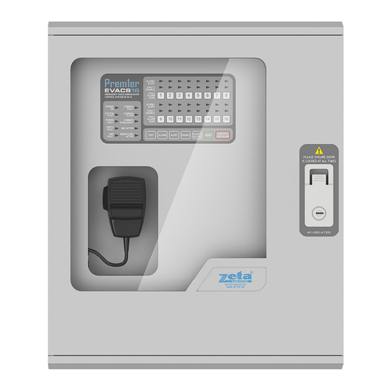
PREMIER EVACS 1-16 INSTRUCTION MANUAL: 2-ZONE NETWORKED VOICE ALARM PANEL Display & Controls Here is the fascia for the Premier EVACS 1-16. Display The Premier EVACS1-16 has the following LED indicators:- COLOUR DESCRIPTION POWER ON GREEN The system has mains and/or battery backup present. The panel showing this LED only is the normal condition. -
Page 12: Controls
PREMIER EVACS 1-16 INSTRUCTION MANUAL: 2-ZONE NETWORKED VOICE ALARM PANEL Controls The Premier EVACS 1-16 has the following controls:- LABEL TEST LED and buzzer test ALARM Used to initiate manual playback of the Evac / Alarm Message ALERT Used to initiate manual playback of the Alert Message DISABLE Used to disable one or more of the speaker channels SILENCE... -
Page 13: Networking The Panel
PREMIER EVACS 1-16 INSTRUCTION MANUAL: 2-ZONE NETWORKED VOICE ALARM PANEL Networking the panel The EVACS 1-16 allows up to 16 panels to be connected over RS485 network interface, with each panel, or module, acting as a 2-channel zone. Individual panels or zones can then be controlled by the master panel. The network address can be set using switches 1-4 of the DIP switch located on the amplifier board. - Page 14 PREMIER EVACS 1-16 INSTRUCTION MANUAL: 2-ZONE NETWORKED VOICE ALARM PANEL The master panel must be configured with the number of zones on the network (that is, the number of EVACS 1-16 panels, including the master panel). This is done with the EVACS 1-16 configuration software via the USB link. To set the number of zones, connect the PC to the EVACS 1-16 panel via a suitable USB cable and run the EVACS 1-16 configuration software.
-
Page 15: Connecting The Evacs 1-16 To An Analogue Addressable Panel
PREMIER EVACS 1-16 INSTRUCTION MANUAL: 2-ZONE NETWORKED VOICE ALARM PANEL Connecting the EVACS 1-16 to an analogue addressable panel The EVACS 1-16 allows connection to an analogue addressable panel via the loop interface. In a network of multiple EVACS 1-16 panels, the CIE must be connected to the master panel. The EVACS 1-16 utilises the Fyreye MKII protocol and must be connected to a panel running the MKII software. -
Page 16: Address Settings
PREMIER EVACS 1-16 INSTRUCTION MANUAL: 2-ZONE NETWORKED VOICE ALARM PANEL Address settings Address SW1 SW2 SW3 SW4 SW5 SW6 SW7 SW8 Address SW1 SW2 SW3 SW4 SW5 SW6 SW7 SW8 Address SW1 SW2 SW3 SW4 SW5 SW6 SW7 SW8 Address SW1 SW2 SW3 SW4 SW5 SW6 SW7 SW8 Not used OFF OFF OFF OFF OFF OFF OFF OFF 64 OFF ON OFF OFF OFF OFF OFF OFF... -
Page 17: Configuring The Voice Messages, And Trigger Inputs
PREMIER EVACS 1-16 INSTRUCTION MANUAL: 2-ZONE NETWORKED VOICE ALARM PANEL Configuring the Voice Messages, and Trigger Inputs The EVACS 1-16 panel can be configured using the EVACS software. To configure the software the panel must be powered on and plugged into the PC running the software using a suitable USB connector. For the EVACS 1-16 the drop-down list box in the centre of the dialogue should be set to EVACS 1-16. -
Page 18: Alarm Configuration
PREMIER EVACS 1-16 INSTRUCTION MANUAL: 2-ZONE NETWORKED VOICE ALARM PANEL Alarm Configuration The alarm configuration dialogue allows the user to upload a custom alarm message, it also allows the user to set the alarm tone used, which is a short tone intended to grab people’s attention before the alarm messages is played. The Readback button on this dialog, as well as the other audio-file configuration dialogs will read the audio file configuration from the EVACS 1-16 and display it on screen: Document no: GLT-237-7-1... -
Page 19: Alert Configuration
PREMIER EVACS 1-16 INSTRUCTION MANUAL: 2-ZONE NETWORKED VOICE ALARM PANEL Alert Configuration This dialog allows the setting of the Alert message and pre-alert tone. Microphone Configuration The microphone signon/signoff dialog allows the customisation of the sign-on and sign-off tones, these are short tones or custom announcements that are played when the microphone is activated and de-activated respectively. - Page 20 PREMIER EVACS 1-16 INSTRUCTION MANUAL: 2-ZONE NETWORKED VOICE ALARM PANEL An example configuration file might look like this: [Alert] Message=C:\Program Files\Zeta Alarms\Messages\AlertFem.wav Tone=7 [Evac] Message=C:\Program Files\Zeta Alarms\Messages\EvacMale.wav Tone=1 [Mic] Signon=C:\Program Files\Zeta Alarms\Page\Page1.wav Signoff= C:\Program Files\Zeta Alarms\Page\Page2.wav [Comms] Port=COM3 [Alert] section: Specifies the message and tone to be played for zones in the ALERT status [Evac] section: Specifies the message and tone to be played for zones in the EVACUATE status [Mic] section: Specifies the audio files to be played for the sign-on and sign-off for the microphone [Comms] section: specifies the communications parameters.
-
Page 21: Channel Volume
PREMIER EVACS 1-16 INSTRUCTION MANUAL: 2-ZONE NETWORKED VOICE ALARM PANEL Channel Volume This provides a volume control interface to set the output volume of each zone. Document no: GLT-237-7-1 PAGE 21 Issue: 1.5 Date: 02/04/2014... -
Page 22: Trigger Matrix
PREMIER EVACS 1-16 INSTRUCTION MANUAL: 2-ZONE NETWORKED VOICE ALARM PANEL Trigger Matrix The trigger matrix tells the panel what to do in the event that the alarm is triggered in a particular zone via the alarm trigger input. In this example the zone activated will go into alarm, whilst all other zones will go into alert; however it is possible to set a variety of configurations using this interface. -
Page 23: Status Monitor
PREMIER EVACS 1-16 INSTRUCTION MANUAL: 2-ZONE NETWORKED VOICE ALARM PANEL Status Monitor This displays the status of all nodes on the network, and reports any errors that may be present. Document no: GLT-237-7-1 PAGE 23 Issue: 1.5 Date: 02/04/2014... -
Page 24: Firmware Update
PREMIER EVACS 1-16 INSTRUCTION MANUAL: 2-ZONE NETWORKED VOICE ALARM PANEL Firmware Update Shows the version of the currently loaded firmware, and provides a utility to update the firmware image: WARNING: firmware updates should NOT be attempted unless under the specific instruction of the manufacturer. An incorrect firmware update may cause the panel to operate outside its design and conformity specifications, and may even cause permanent damage to the panel. -
Page 25: Methods Of Operating The Premier Evacs 1-16
PREMIER EVACS 1-16 INSTRUCTION MANUAL: 2-ZONE NETWORKED VOICE ALARM PANEL Methods of Operating the Premier EVACS 1-16 The Premier EVACS 1-16 can operate in any one of the following ways:- 1. LIVE BROADCAST The microphone is used to broadcast information about the alarm, and the responsible person would direct occupants what to do next. -
Page 26: Fault Display & Fault-Finding
PREMIER EVACS 1-16 INSTRUCTION MANUAL: 2-ZONE NETWORKED VOICE ALARM PANEL Fault display & fault-finding The Premier EVACS 1-16 panel monitor for the following faults:- Power Supply Fault Speaker Channel open-circuit wiring fault Speaker Channel short-circuit wiring fault Earth Fault Amplifier Fault System Fault The Premier EVACS 1-16 Voice Alarm panel also has a General Fault LED that will light when any fault is present. -
Page 27: Speaker Circuit Fault
PREMIER EVACS 1-16 INSTRUCTION MANUAL: 2-ZONE NETWORKED VOICE ALARM PANEL Speaker Circuit Fault A Speaker Circuit Fault is indicative of one or more of the following faults:- Speaker Circuit Open Circuit fault. Check that there are no breaks in the cable, and that all screw connections are secure. As a panel check, disconnect the circuit indicating the fault, and press the calibrate button. -
Page 28: Specifications
PREMIER EVACS 1-16 INSTRUCTION MANUAL: 2-ZONE NETWORKED VOICE ALARM PANEL Battery calculation As a general rule the battery selected as a backup power source for the panel should be calculated to provide at least 24 hours of standby power, plus 30 minutes power in the alarm condition plus a 25% reserve to account for battery life degradation, environmental factors or unexpected power drains. - Page 29 PREMIER EVACS 1-16 INSTRUCTION MANUAL: 2-ZONE NETWORKED VOICE ALARM PANEL Consider a system consisting of: 1x 12W speaker system 1x 8W speaker system 100mA equipment draw on Aux power 300mA equipment draw on Aux power during alarm 480mA sounder channel 1 360mA sounder channel 2 The system must remain on standby for 24 hours The system must also be able to handle the alarm condition for a minimum of 1 hour...
- Page 30 PREMIER EVACS 1-16 INSTRUCTION MANUAL: 2-ZONE NETWORKED VOICE ALARM PANEL Battery calculation worksheet This worksheet can be filled out to calculate the batteries size required for a given installation. Standby requirements Quiescent current Auxiliary equipment Total standby current x standby time of: Alarm requirements System current Auxiliary equipment...
- Page 31 PREMIER EVACS 1-16 INSTRUCTION MANUAL: 2-ZONE NETWORKED VOICE ALARM PANEL Audio Power The following graphs demonstrate typical performance characteristics for the Evacs 1-16. The test panel was configured in standalone mode and audio output was set as a 1 KHz sine wave with each speaker output played into a 575Ω...
- Page 32 PREMIER EVACS 1-16 INSTRUCTION MANUAL: 2-ZONE NETWORKED VOICE ALARM PANEL Power consumption These graphs show typical power consumption characteristics from both a main power source and a backup power source. The power consumption data includes a small overhead of roughly 300mA drawn by the system. Power consumption vs Output power Power consumption vs Volume setting 1KHz continuous sine wave...
- Page 33 PREMIER EVACS 1-16 INSTRUCTION MANUAL: 2-ZONE NETWORKED VOICE ALARM PANEL Specifications Electrical Specifications ELECTRICAL DESCRIPTION VALUE MAINS VOLTAGE 100-120V AC / 200-240V AC ± 10% @ 50/60Hz MAINS CURRENT 8.0A MAX SYSTEM VOLTAGE 29.5V NOMINAL ± 10% QUIESCIENT CURRENT DRAW 60mA ALARM CONDITION CURRENT DRAW 500mA...
Need help?
Do you have a question about the PREM1ER EVACS 1-16 and is the answer not in the manual?
Questions and answers