Table of Contents
Advertisement
Quick Links
T
F
& G
D
ELEFIRE
IRE
AS
ETECTORS
PO Box 7036
Petach Tikva 49250
Israel
Tel:
972 3 970 0400
Fax:
972 3 921 1816
eMail:
marketing@telefire.co.il
Web:
www.telefire.co.il
Fire Alarm and Extinguishing
L
TD
TSA-1000
Conventional
Multi-Zone
Control Panel
Technical Manual
TSA- - - - 1000
TSA
TSA
TSA
Revision 1.12
April 2012
1000En
En112
112.pdf
.pdf
1000
1000
En
En
112
112
.pdf
.pdf
Advertisement
Table of Contents

Related Manuals for Telefire TSA-1000


Summary of Contents for Telefire TSA-1000
- Page 1 TSA-1000 Conventional Multi-Zone Fire Alarm and Extinguishing Control Panel Technical Manual & G ELEFIRE ETECTORS PO Box 7036 Petach Tikva 49250 TSA- - - - 1000 1000En En112 112.pdf .pdf 1000 1000 .pdf .pdf Israel Tel: 972 3 970 0400...
- Page 2 Information supplied by TELEFIRE FIRE AND GAS DETECTORS is believed to be accurate and reliable. However, no responsibility is assumed by TELEFIRE FIRE AND GAS DETECTORS for the use thereof nor for the rights of third parties, which may be effected in any way by the use thereof.
- Page 3 TSA-1000 © 2008 – 2012 Telefire Fire & Gas Detectors Ltd Revision 1.12 Record of Changes Date Revision Details Author 25.01.2012 1.12 Update Introduction, Para 2.2 (UL), I. Reshef UPDATE SYMBOLIC DIAGRAM, Update note about reading and UNDERSTANDING this document Move Number of adapters and extinguishant quantities to appear after "Extinguishing Adapters"...
-
Page 4: Table Of Contents
TSA-1000 © 2008 – 2012 Telefire Fire & Gas Detectors Ltd Revision 1.12 Table of Contents INTRODUCTION ....................1 FUNCTIONS AND OPTIONS.................3 EN 54-2 O ............3 PTIONS WITH EQUIREMENTS UL 864 ......................3 IMPORTANT NOTES ..................4 ..................4 ANUAL RIGGERING ............... - Page 5 TSA-1000 © 2008 – 2012 Telefire Fire & Gas Detectors Ltd Revision 1.12 USER INTERFACE-DISPLAY AND KEYBOARD ........26 ................26 ENERAL ISPLAY ........30 IGITAL ISPLAY AND IGITAL ISPLAY NDICATORS ..................31 NDICATORS ....................31 EYBOARD 10 WORK STATES ...................33 10.1...
- Page 6 TSA-1000 © 2008 – 2012 Telefire Fire & Gas Detectors Ltd Revision 1.12 13.8 – E ..53 YPICAL PPLICATION XTINGUISHING AND LECTRICITY ISCONNECT 14 CONTROL PANEL PROGRAMMING............55 14.1 ..................55 TRUCTURE 14.2 ..............55 NTERING ROGRAMMING 14.3 ............55...
- Page 7 TSA-1000 © 2008 – 2012 Telefire Fire & Gas Detectors Ltd Revision 1.12 19.1 – T ....75 EEKLY NSPECTION ERFORMED BY ERSONNEL 20 CERTIFICATION ..................76 — V —...
- Page 8 Figure 29 Display during output programming List of Tables Table 1 Technical Specifications Table 2 TSA-1000 – number of inputs and outputs of the various configurations Table 3 IDC cable selection Table 4 Wiring Characteristics’ influence on System Performance — VI...
-
Page 9: Introduction
TSA-1000C, a communication expansion card). Computer communication and remote panels are also supported through the TSA-1000C The TSA-1000 supervises two-wire IDC lines ("zones") and outputs that can be used to activate sounders, automatic extinguishing devices, evacuation sounders, or other notification equipment. Additionally, the control panel has separate outputs for activating a main sounder, automatic dialer, and "dry"... - Page 10 System log can be viewed via a PC or printed for system investigation purposes. The TSA-1000 can be connected to form a network of control panels. – Page 2 of 2 –...
-
Page 11: Functions And Options
Functions and Options EN 54-2 Options with Requirements The TSA-1000 conforms fully to European standards BS EN 54-2:1998 and BS EN 54-4:1998 and the following optional features: Output to fire alarm devices – EN 54-2 Section 7.8 option with requirements •... -
Page 12: Important Notes
Extinguishing Triggering Device of the correct color as per EN 12094-3. Dependency on More Than One Alarm Signal The TSA-1000 supports Coincidence detection– per EN 54-2 Section 7.12 option with requirements (Provided as a two zones coincidence and as a single/Dual zone AVF- Alarm Verification Function) The "Dependency on more than one alarm signal"... -
Page 13: Two Zones Coincidence
Maintenance, page 65. Coincidence detection– EN 54-2 Section 7.12 option with requirements is implemented in the TSA-1000 as a two zones coincidence and as a single/Dual zone AVF- Alarm Verification Function). AVF was explained above. "Two Zones Coincidence" is explained below... -
Page 14: Note Regarding Default Configuration
3.7.1 Environmental Limits and Protection Level The TSA-1000 environmental limits are specified in EN-54-02:1998 para. 12. The TSA-1000 is specified for -5° C to +40° C, RH max 95% temperature range, and IP30 protection level. Note Routing cables into the ECD and maintaining the protection level, page 38, for information about maintaining the protection level. -
Page 15: Figure 1 Tsa-1000 Typical System
TSA-1000 © 2008 – 2012 Telefire Fire & Gas Detectors Ltd Revision 1.12 sequence, until the faulty output is isolated. All appropriate "good" outputs are then switched back ON, except for the faulty outputs. The controlled outputs (i.e. not relays' contacts or OC outputs) are continuously monitored. -
Page 16: Terms, Definitions And Abbreviations
TSA-1000 © 2008 – 2012 Telefire Fire & Gas Detectors Ltd Revision 1.12 Terms, Definitions and Abbreviations Abbreviations: Abbreviation Meaning Remarks Control Panel Electrical Automatic Control and Delay Device Terminal Block Manual Call Point Push Button Personal Computer Power Supply... -
Page 17: Safety
TSA-1000 © 2008 – 2012 Telefire Fire & Gas Detectors Ltd Revision 1.12 Safety Note Do not install commission, operate, or maintain this product before fully reading and thoroughly understanding this manual. Note Whenever possible, disconnect all power sources (Line AND Battery) from the product before performing any work on the ECD. -
Page 18: Batteries Handling And Safety
TSA-1000 © 2008 – 2012 Telefire Fire & Gas Detectors Ltd Revision 1.12 Batteries Handling and Safety Note Batteries require special care and safety precautions. Refer to the batteries’ manufacturer literature for full information. The following information supplements and highlights manufacturer’s information. -
Page 19: Access Levels
The control panel provides protection from unauthorized access of certain functions by various access levels. The TSA-1000 includes electronic and mechanical mechanisms that enact 4 access levels, as per EN 54-02 Annex A: Access level 1 – not limited, immediate access by operator •... -
Page 20: Technical Specifications
A metal enclosure with a hinged and mechanically lockable door. The door also • serves as the front panel PS40W Power Supply / Charger • TSA-1000 Main Board (1 change polarity output, 5 level activation outputs, 4 inputs, • 3 relays) TSA-1000D Display board •... -
Page 21: Tsa-1000C Communication Expansion Module
TSA-1000 © 2008 – 2012 Telefire Fire & Gas Detectors Ltd Revision 1.12 TSA-1000C Communication Expansion module The TSA-1000C communication expansion provides the following communication and networking capabilities; RS-232 ................. 1 – for PC connection RS-485 ................. 2 – remote panels and .................. -
Page 22: Table Of Technical Specifications, Tsa-1000
TSA-1000 © 2008 – 2012 Telefire Fire & Gas Detectors Ltd Revision 1.12 April 2012 Table of Technical Specifications, TSA-1000 ITEM RATING REMARKS COMMUNICATION PARAMETERS MECHANICAL Dimensions (W / H / D) 370 / 290 / 90 mm Weight (excluding batteries) TSA-1000E4 or TSA-1000E8 3,470 gr. - Page 23 TSA-1000 © 2008 – 2012 Telefire Fire & Gas Detectors Ltd Revision 1.12 April 2012 ITEM RATING REMARKS COMMUNICATION PARAMETERS Battery Type Two 12V 5AH connected in series Yuasa NP 12-5 or equivalent Battery Charge Voltage 27.3V±0.2V Modulated DC Battery Charge Current 0.3A max.
- Page 24 TSA-1000 © 2008 – 2012 Telefire Fire & Gas Detectors Ltd Revision 1.12 April 2012 ITEM RATING REMARKS COMMUNICATION PARAMETERS with TSA-1000E4 and TSA-1000- 200 mA EM083 with TSA-1000E8 and TSA-1000- 210 mA EM083 with TSA-1000E8 and TSA-1000- 250 mA...
- Page 25 TSA-1000 © 2008 – 2012 Telefire Fire & Gas Detectors Ltd Revision 1.12 April 2012 ITEM RATING REMARKS COMMUNICATION PARAMETERS MB out 3 Level Act. 24V DC, 0.8A, Current limited, Programmable, Silenceable Modulated DC MB out 4 Level Act. 24V DC, 0.8A, Current limited,...
- Page 26 TSA-1000 © 2008 – 2012 Telefire Fire & Gas Detectors Ltd Revision 1.12 April 2012 ITEM RATING REMARKS COMMUNICATION PARAMETERS E8 (inputs) Expansion card Input 1 See MB inputs for inputs characteristics E8 card Inputs are monitored Input 2 Input 3...
- Page 27 TSA-1000 © 2008 – 2012 Telefire Fire & Gas Detectors Ltd Revision 1.12 April 2012 ITEM RATING REMARKS COMMUNICATION PARAMETERS OC 8 24V Nominal, 50mA EM083 RELAYS Relay 1 See MB relays for relays characteristics Relay 2 Relay 3 EM422 Expansion Card...
-
Page 28: Table 1 Technical Specifications
TSA-1000 © 2008 – 2012 Telefire Fire & Gas Detectors Ltd Revision 1.12 April 2012 ITEM RATING REMARKS COMMUNICATION PARAMETERS TSA-1000C – Communication Module RS-232 1 For PC connection RS-232 RS-485 2 Remote panels and networking RS485 FWRE 1 Fault dialer... -
Page 29: Default Ports Allocation And Configuration
© 2008 – 2012 Telefire Fire & Gas Detectors Ltd Revision 1.12 Default Ports Allocation and Configuration By default, all the TSA-1000 inputs are detector zones inputs, and all outputs (except horn and alarm dialer) are general outputs. To modify these settings the TSA-1000 must be programmed. -
Page 30: Tsa-1000 Control Panel Assembly
Figure 2 Module location Power Supply, Charger and Batteries The TSA-1000 is powered by the PS40_W Power Supply/Charger, which is located at the top left corner of the enclosure/. The PS40_W requires 230VAC, +10%, -15%, 50/60Hz. It is protected by a 5x20 mm, 3.15A glass Fast-Blow fuse, located at the bottom left corner of the PS_40W (F2). -
Page 31: Main Board
TSA-1000-E4 – an expansion module for 4 inputs • TSA-1000-E8 – an expansion module for 8 inputs • TSA-1000-EM422 – an expansion module to the TSA-1000-E8 that includes 4 • inputs, 2 supervised programmable outputs and 2 programmable relays (prerequisite: TSA-1000E8) TSA-1000-EM083 –... -
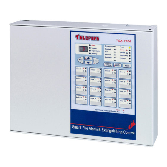
Page 32: Front Door
1000-E8 + TSA-1000E422 Table 2 TSA-1000 – number of inputs and outputs of the various configurations Front Door A front door completes and closes the CP box and enacts access level 4 for some operations, since it needs a tool (screwdriver) for opening. It also serves as a front panel, as it has a display and a keyboard, which includes separate indicating LEDs, programming keys, and a 3-digit 7 segments display. -
Page 33: Figure 3 Display And Keyboard
TSA-1000 © 2008 – 2012 Telefire Fire & Gas Detectors Ltd Revision 1.12 Figure 3 Display and Keyboard – Page 25 of 25 –... -
Page 34: User Interface-Display And Keyboard
© 2008 – 2012 Telefire Fire & Gas Detectors Ltd Revision 1.12 User Interface-Display and Keyboard The front door of the TSA-1000 also serves as the user interface, and contains a display and a keyboard. The display has three distinct areas:... - Page 35 TSA-1000 © 2008 – 2012 Telefire Fire & Gas Detectors Ltd Revision 1.12 Its Color and meaning Its Color and meaning (UL 864 (EN 54 / CP 10 version) / IS 1220 version) Alarm Red LED. Indicates fire alarm. Red LED. Indicates fire alarm.
- Page 36 TSA-1000 © 2008 – 2012 Telefire Fire & Gas Detectors Ltd Revision 1.12 Its Color and meaning Its Color and meaning (UL 864 (EN 54 / CP 10 version) / IS 1220 version) Telecom Red/Yellow LED. Indicates a Red/Yellow LED. Indicates a fault event in the dialer line.
- Page 37 TSA-1000 © 2008 – 2012 Telefire Fire & Gas Detectors Ltd Revision 1.12 Its Color and meaning Its Color and meaning (UL 864 (EN 54 / CP 10 version) / IS 1220 version) Power Green LED. Indicates the Green LED. Indicates the presence of AC input or battery.
-
Page 38: Digital Display And Digital Display Indicators
TSA-1000 © 2008 – 2012 Telefire Fire & Gas Detectors Ltd Revision 1.12 Its Color and meaning Its Color and meaning (UL 864 (EN 54 / CP 10 version) / IS 1220 version) Ground Fault Yellow LED. Indicates a ground Yellow LED. -
Page 39: Zone Indicators
TSA-1000 © 2008 – 2012 Telefire Fire & Gas Detectors Ltd Revision 1.12 Figure 5 Digital Display and Digital Display Indicators Zone Indicators Each zone has 2 LEDs in the zone indication area that indicates the alarm and fault in that zone. - Page 40 TSA-1000 © 2008 – 2012 Telefire Fire & Gas Detectors Ltd Revision 1.12 Function Menu Enter Menu Arrows Paging through memory Buzzer Off / Is used for silencing the internal alarm buzzer and fault buzzer • Ack / Prog in the control panel Acknowledges new event.
-
Page 41: Work States
TSA-1000 © 2008 – 2012 Telefire Fire & Gas Detectors Ltd Revision 1.12 Work States During an alarm, fault or supervisory event on the system, the event is clearly shown by dedicated LEDs that are labeled Fire Alarm, Fault, and Supervisory, respectively. A detailed explanation in the digital display will include all the details necessary for troubleshooting the event and proper resolution. -
Page 42: Fault State
• and clarification area and the private LEDs in the zones and turning them ON (UL version only) 10.4 Supervisory State The TSA-1000 has a supervisory function that conforms to UL and EN standards. – Page 34 of 34 –... -
Page 43: Disablement State
TSA-1000 © 2008 – 2012 Telefire Fire & Gas Detectors Ltd Revision 1.12 In certain cases, there is a need to activate an output following a fault such as indication of low pressure in an extinguishing cylinder, closed sprinkler valve, etc. -
Page 44: Installation
CP 10 Requirement CP 10 CP-10 allows up to 20 smoke detectors or up to 40 heat detectors per zone. The TSA-1000 was tested and certified to CP-10 based on these limitations. 11.1.2 Calculating Current Requirement and Battery Capacity For every control panel calculate the total current consumption of all devices such as sounder, beacons, extinguishing cylinders, automatic dialer etc. -
Page 45: Mounting
11.2 Mounting 11.2.1 Environmental Limits The TSA-1000 is a class A (-5° C to +40° C, RH max 95%) temperature range device. Its environmental protective level is IP30. Note See "installation instructions" for information about maintaining the protection level... -
Page 46: Wiring
Avoid locating the control panel in direct sunlight Mount the TSA-1000 to a solid wall so it will have comfortable access to connecting the cables from the input and output devices and maintenance personnel for ongoing operations and in a location where it is possible to supervise and clearly see the display and indicators. - Page 47 11.3.2 Wiring Information The TSA-1000 is supplied in working condition, fully assembled, and with all internal modules pre-wired. Wiring instructions are only for connecting the system to AC input, zones, programmable output and general output.
-
Page 48: Figure 9 Routing High- And Low Voltage Cables In The Tsa-1000 Chassis
The wiring cables and input and system output shall be separate from mains AC input – see Figure 9. Figure 9 Routing High- and Low Voltage cables in the TSA-1000 Chassis 11.3.5 24Vdc Powered Devices To ensure operation of alarm or initiating device that requires relatively high current from a 24 Vdc source, use appropriate cables. -
Page 49: Figure 10 Rm-1000 Connection
TSA-1000 © 2008 – 2012 Telefire Fire & Gas Detectors Ltd Revision 1.12 11.3.6 Output Wiring Activation circuit cabling between the 24Vdc source to the output device such as sounders, extinguishing devices, strobes, etc., shall be calculated to a maximum voltage drop of 3V or a voltage drop that will leave the device with the lowest operating voltage specified by the manufacturer –... -
Page 50: Installing Detectors, Input And Output Devices, And Other Devices
TSA-1000 © 2008 – 2012 Telefire Fire & Gas Detectors Ltd Revision 1.12 11.4 Installing Detectors, Input and Output Devices, and Other Devices 11.4.1 Connecting Zones and Outputs Note Measure the wiring to ensure there are no shorts before connecting the wiring to the control panel. -
Page 51: Figure 13 Expansion Module Connectors
TSA-1000 © 2008 – 2012 Telefire Fire & Gas Detectors Ltd Revision 1.12 Figure 13 Expansion Module Connectors Figure 14 Connecting Two Detectors and a TPB-10R Break-Glass Figure 15 Connecting Programmable and General Sounders – Page 43 of 43 –... -
Page 52: Connecting The Mains, Batteries And The Ground Wire
TSA-1000 © 2008 – 2012 Telefire Fire & Gas Detectors Ltd Revision 1.12 11.5 Connecting the mains, batteries and the ground wire. SEE SAFETY, page 9 Routing cables into the ECD and maintaining the protection level, page 38 Connect the control panel’s AC input line directly to a dedicated circuit breaker that is not shared by other appliances or equipment. -
Page 53: Post-Installation
Ensure that you set the date and time after powering on (see section 15.7 on page 66). The clock/calendar circuit includes a power backup for about five hours without power sources – verify and set the time and date if the TSA-1000 was powered off more than 5 hours. -
Page 54: Connecting Atdm-500 I Dialer
TSA-1000 © 2008 – 2012 Telefire Fire & Gas Detectors Ltd Revision 1.12 Warning Forgotten passwords require factory reset: if you lose or forget the password, the panel must be sent back to the factory to be initialized. There is no field option for gaining access to the panel without a valid password. - Page 55 TSA-1000 © 2008 – 2012 Telefire Fire & Gas Detectors Ltd Revision 1.12 Note The dotted lines in Figure 17 are required only for error message notifications. Configure the dialer (option 6) to 11. – Page 47 of 47 –...
-
Page 56: Extinguishing
12.4 Emergency Hold and Emergency Abort The TSA-1000 supports emergency hold and emergency abort as per EN-12094-1. Pressing an emergency hold switch will start one of the following sequences: The extinguishing signal shall not be activated as long as the emergency hold •... -
Page 57: Actions To Perform After Extinguishing Activation
Press Menu to enter the main menu. Press the ▲ or ▼ keys until the display shows PG (programming mode). Press Enter to enter programming mode. The display will flash PAS (password) and the TSA-1000 will wait for the password (default 2222). Key-in the password and then perform RESET. -
Page 58: Connecting Extinguishing Equipment
TSA-1000 © 2008 – 2012 Telefire Fire & Gas Detectors Ltd Revision 1.12 Connecting Extinguishing Equipment 13.1 Extinguishing Adapters In order to connect the ECD extinguishing output to different actuators, it is necessary to connect adapters between the ECD output and the extinguishing equipment input, Telefire offers several adapters. -
Page 59: Extinguishant Quantities
TSA-1000. Additional containers may be activated with a delay of at least 20 seconds between activations It is possible to connect a single GCA-activated container to the TSA-1000 – this will • be connected only to output 1 (see Figure 19) It is possible to connect one GreenEX aerosol releasing device to each •... -
Page 60: Fike Gca
TSA-1000 verify that jumpers JP5 and JP6 are shorted. When connecting a TLA-3K module to programmable all other outputs in a TSA-1000 ensure that jumpers JP1 and JP2 are shorted and jumpers JP4 and JP5 are shorted. See Figure 20 above. -
Page 61: Firepro Aerosol Containers
13.8 A Typical Application – Extinguishing and Electricity Disconnect The following example shows a TSA-1000 that is configured to activate extinguishing by cross-zone of zones 2 and 3, or activation of a manual extinguishing call point on zone 4; activating an extinguishing release sign on output 2; activating an evacuation horn on output 3;... -
Page 62: Figure 22 A Typical Application - Cross-Zone Activation Of Electricity Disconnect
TSA-1000 © 2008 – 2012 Telefire Fire & Gas Detectors Ltd Revision 1.12 Output 1 – extinguishing output (E); 30 second delay; activated by cross-zone of • inputs 2 and 3, or input 4; not delayed Outputs 2 and 3 – activated by cross-zone (A) of inputs 2 and 3, or input 4; not •... -
Page 63: Control Panel Programming
© 2008 – 2012 Telefire Fire & Gas Detectors Ltd Revision 1.12 Control Panel Programming The TSA-1000's operating parameters can be easily modified in the field to allow for the specific requirements of each site. System parameters modification is limited to access level 3 (programmer). -
Page 64: Display During Programming
TSA-1000 © 2008 – 2012 Telefire Fire & Gas Detectors Ltd Revision 1.12 Function in Programming Mode ▲ (2) Navigates between options available in the selected field ▼ (3) Navigates between options available in the selected field Enter (4) Selects, marks or removes a zone from the matrix... -
Page 65: Programming Sequence
TSA-1000 © 2008 – 2012 Telefire Fire & Gas Detectors Ltd Revision 1.12 Figure 24 The seven-segment display and representation of digits and letters 14.5 Programming Sequence 14.5.1 Programming Steps There are five steps to programming the control panel: Enter programming mode •... -
Page 66: Dialer Programming
TSA-1000 © 2008 – 2012 Telefire Fire & Gas Detectors Ltd Revision 1.12 Press the Menu key to move the cursor to select verification for input devices or • silenced for output devices (Alarm LED) or delay Press the Menu key to move the cursor to select the input zones for the matrix •... -
Page 67: Remote Annunciator Programming
(0 – not configured, E – English, S – Secondary language). 14.10 Network Programming TSA-1000 control panel networking is in main/sub configuration. All panels require the optional TSA-1000C communication network. Physical connection is via a two-wire RS-485 cable. A single Master Panel (panel No. 1) supervises up to 12 Sub Panels (panel addresses 5 to 16). -
Page 68: Figure 26 Display During Relay Programming
TSA-1000 © 2008 – 2012 Telefire Fire & Gas Detectors Ltd Revision 1.12 Figure 26 Display during relay programming 14.11.1 Additional Parameters for General Relays A relay that is defined as a General relay can be programmed as an Alarm relay, Fault relay, or Supervisory relay using the LEDs to the right of the digital display. -
Page 69: Zone Programming
TSA-1000 © 2008 – 2012 Telefire Fire & Gas Detectors Ltd Revision 1.12 Note A relay that is defined as a Fault relay will be energized when the system is powered and in normal state (see diagram below). Figure 27 Programmable Relay Contacts During Normal Operations and Upon Activation 14.12... -
Page 70: Output Programming
TSA-1000 © 2008 – 2012 Telefire Fire & Gas Detectors Ltd Revision 1.12 Figure 28 Display during input programming CP 10 CP 10 Requirement CP-10:2005 section 2.5.11 states "the following components shall not be subject to alarm verification feature: (a) Alarm zone facilities containing only manual call points... -
Page 71: Figure 29 Display During Output Programming
TSA-1000 © 2008 – 2012 Telefire Fire & Gas Detectors Ltd Revision 1.12 Figure 29 Display during output programming 14.13.1 Additional Parameters for General Outputs An output that is defined as a General output can be programmed as an Alarm output or Supervisory output using the LEDs to the right of the digital display. -
Page 72: Saving Data And Exiting Programming Mode
TSA-1000 © 2008 – 2012 Telefire Fire & Gas Detectors Ltd Revision 1.12 14.13.3 Additional Parameters for Logical "Or" Outputs An output that is defined as a Logical "Or" output can be programmed as an Alarm or Supervisory output using the LEDs to the right of the digital display. -
Page 73: Operation And Maintenance
TSA-1000 © 2008 – 2012 Telefire Fire & Gas Detectors Ltd Revision 1.12 Operation and Maintenance 15.1 Evacuation (EVC) Press the Menu key to enter the main menu. Press the ▲ or ▼ keys until the display shows EVC. Press the Enter key to activate all general outputs. -
Page 74: Event Log (Log)
TSA-1000 © 2008 – 2012 Telefire Fire & Gas Detectors Ltd Revision 1.12 During the test the zone number and the alarm LED will light for 15 seconds. In case of an alarm or fault events that occur during field test the digital display will indicate them with a higher priority. -
Page 75: Lamp Test (Lt)
TSA-1000 © 2008 – 2012 Telefire Fire & Gas Detectors Ltd Revision 1.12 To exit without modifying the time and date press the Reset key, the system will display nSv (not Saved). This message will be displayed only when performing changes. -
Page 76: Troubleshooting
The TSA-1000 will indicate the zone with detector and maintenance fault by indicating the number of the zone in the left and middle digits in the digital display and by alternating the top and bottom lines in the right digit. - Page 77 TSA-1000 © 2008 – 2012 Telefire Fire & Gas Detectors Ltd Revision 1.12 – Open wire on Horn output Horn output disabled Short wire on Horn output 24Vdc fault 24Vdc (resettable) fault Short wire on zone # – Open wire on zone # Ξ...
-
Page 78: Programming Faults
TSA-1000 © 2008 – 2012 Telefire Fire & Gas Detectors Ltd Revision 1.12 EPROM failure – return to manufacturer for repair – Ground fault – negative wire leakage ┤ Ground fault – positive wire leakage Note Ground leakage faults may affect output fault display. Resolve the ground fault issues first. - Page 79 TSA-1000 © 2008 – 2012 Telefire Fire & Gas Detectors Ltd Revision 1.12 A relay was defined without defining output type Non-consecutive relay number (e.g., an expansion module was configured as relays 5 – 7 instead of 4 – 6)
-
Page 80: Commissioning
TSA-1000 © 2008 – 2012 Telefire Fire & Gas Detectors Ltd Revision 1.12 Commissioning Verify that ALL POWER SOURCES are disconnected. • Verify that THE EXTINGUISHER IS DISCONNECTED (disconnect both wires to the • extinguisher), connect a DUMMY load to the extinguisher output. - Page 81 TSA-1000 © 2008 – 2012 Telefire Fire & Gas Detectors Ltd Revision 1.12 Document issue number and date • If the document is not attached to the CP front panel, a note at the bottom stating • that it shall be framed and placed near the CP for ready reference.
-
Page 82: Maintenance
TSA-1000 © 2008 – 2012 Telefire Fire & Gas Detectors Ltd Revision 1.12 Maintenance No specific maintenance is required for the TSA1000. Keep the TSA1000 clean and dry. If necessary, clean the outside of the enclosure with a slightly damp cloth. -
Page 83: Routine Testing
Revision 1.12 Routine Testing The TSA-1000 shall be tested weekly as specified in the next paragraph. The system should be fully tested at least twice a year, or as required by national and/or local fire codes. All devices, system wiring and component functions should be tested and maintained. - Page 84 TSA-1000 © 2008 – 2012 Telefire Fire & Gas Detectors Ltd Revision 1.12 Certification Telefire’s TSA-1000 Conventional Multi-Zone Fire Alarm and Extinguishing Control Panel has the following approvals: EN 54-2 and EN 54-4 Certified • SI 1220 Certified • GOST 53325-2009 Certified •...
- Page 85 Resolving the fault will automatically restore the system to normal operating conditions. Silencing Buzzer Off" To silence the internal buzzer press the " key. Please refer to the TSA-1000 Technical Manual for further details. Zone Description Zone Description Service Representative Name:___________Address:________________________________...
Need help?
Do you have a question about the TSA-1000 and is the answer not in the manual?
Questions and answers