Table of Contents
Advertisement
T
F
& G
D
ELEFIRE
IRE
AS
ETECTORS
PO Box 7036
Petach Tikva 49250
Israel
Tel:
972 3 970 0400
Fax:
972 3 921 1816
eMail:
info@telefire.co.il
Web:
www.telefire.co.il
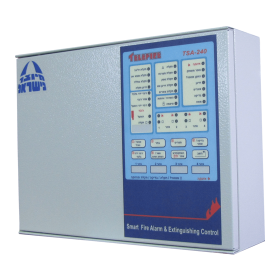
TSA-200 / TSA-200XT
TSA-240 / TSA-240XT
Fire Alarm Control Panel
L
TD
and
Conventional
Two-and Four-Zone
Technical Manual
TSA- - - - 200
TSA
TSA
TSA
Revision 1.06
July 2014
200En
En106
106.pdf
.pdf
200
200
En
En
106
106
.pdf
.pdf
Advertisement
Table of Contents

Related Manuals for Telefire TSA-200


Summary of Contents for Telefire TSA-200
- Page 1 TSA-200 / TSA-200XT TSA-240 / TSA-240XT Conventional Two-and Four-Zone Fire Alarm Control Panel Technical Manual & G ELEFIRE ETECTORS PO Box 7036 Petach Tikva 49250 TSA- - - - 200 200En En106 106.pdf .pdf .pdf .pdf Israel Tel: 972 3 970 0400...
- Page 2 Information supplied by TELEFIRE FIRE AND GAS DETECTORS is believed to be accurate and reliable. However, no responsibility is assumed by TELEFIRE FIRE AND GAS DETECTORS for the use thereof nor for the rights of third parties, which may be affected in any way by the use thereof.
- Page 3 TSA-200 / TSA-200XT / TSA-240 / TSA-240XT © 2010 – 2014 Telefire Fire & Gas Detectors Ltd Revision 1.06 July 2014 Record of Changes Date Revision Details Author 14.04.2011 1.00 Initial Release I. Reshef 17.07.2011 1.01 Minor corrections-update front panel display functions.
- Page 4 “Fault” as used in EN 54 standards are used interchangeably throughout this manual Note All maintenance and repair work performed on the TSA-200 shall be performed by qualified and authorized personnel ONLY Note Do not install, operate, or maintain this product before fully reading and thoroughly understanding this manual.
-
Page 5: Table Of Contents
TSA-200 / TSA-200XT / TSA-240 / TSA-240XT © 2010 – 2014 Telefire Fire & Gas Detectors Ltd Revision 1.06 July 2014 Table of Contents INTRODUCTION .................... 1 FUNCTIONS AND OPTIONS ................. 2 EN 54-2 – O ............2 PTIONS WITH EQUIREMENTS UL 864 ...................... - Page 6 TSA-200 / TSA-200XT / TSA-240 / TSA-240XT © 2010 – 2014 Telefire Fire & Gas Detectors Ltd Revision 1.06 July 2014 ..........21 NCLOSURE AND AJOR UBASSEMBLIES ..........22 OWER UPPLY HARGER AND ATTERIES ....................22 RONT ANEL INSTALLATION ................... 23 ..............
- Page 7 TSA-200 / TSA-200XT / TSA-240 / TSA-240XT © 2010 – 2014 Telefire Fire & Gas Detectors Ltd Revision 1.06 July 2014 13.2 ................... 43 AULT ISPLAY 13.3 ..............44 ISCELLANEOUS ISPLAY 13.4 ..................45 NDICATORS 13.5 ....................46 EYBOARD 13.6 ..............
- Page 8 Module location ..................21 Figure 3 Chassis Mounting Holes ................24 Figure 4 Routing cables in the TSA-200 product family Enclosure ......26 Figure 5 TSA-200 / TSA-200XT Connectors Label ........... 29 Figure 6 TSA-240 / TSA-240XT Connectors Label ........... 29 Figure 7 Typical Fire Alarm, (Non Extinguishing) Connections .........
- Page 9 © 2010 – 2014 Telefire Fire & Gas Detectors Ltd Revision 1.06 July 2014 Figure 16 Connecting a TSA-200 product family to a supervising control panel ..40 Figure 17 Front Panel ....................41 Figure 18 General Display Area ................. 42 Figure 19 Fault Display Area ..................
-
Page 10: Introduction
Drawing on over three decades' of experience in designing and manufacturing fire alarm Control and Indicating Equipment (CIE), the state of the art TSA-200 / TSA-200XT / TSA-240 / TSA-240XT Conventional Two- and Four-Zone Fire Alarm Control and Indicating Equipment (CIE) is certified to EN 54-2 and EN 54-4;... -
Page 11: Functions And Options
Test condition – EN 54-2 Section 10 option with requirements • UL 864 The TSA-200 / TSA-200XT / TSA-240 / TSA-240XT, human interface also conforms to UL 864 edition 9. TSA-200XT / TSA-240XT Extinguishing-Specific Functions In addition to the EN 54-2 requirements and options with requirements detailed above, the TSA-200XT and TSA-240XT also provides the following additional functions Extinguishing Delay, 0 or 30 Sec, User Programmable. -
Page 12: Important Notes
TSA-200 / TSA-200XT / TSA-240 / TSA-240XT © 2010 – 2014 Telefire Fire & Gas Detectors Ltd Revision 1.06 July 2014 Important Notes A detailed explanation of the operation of the ECD is provided later. The information in the current chapter is provided to highlight certain issues. -
Page 13: Note Regarding Default Configuration
Both models are certified to EN 54-2 and EN 54-4, and are CE marked. UL 864 compatibility The Display Logic of the TSA-200 product family is that of UL 864, edition 9, where some events, i.e. Alarm and Fault (System generated events) are displayed by flashing indicators, changing indication to ON (steady) when acknowledged. -
Page 14: Suitability Of Use In Various Environments
3.9.2 Suitable Environment The TSA-200 product family environmental limits are stated above. It is to be installed in an indoors location, well ventilated location, protected from the elements. Avoid locating the CP in direct sunlight or near sources of heat. - Page 15 TSA-200 / TSA-200XT / TSA-240 / TSA-240XT © 2010 – 2014 Telefire Fire & Gas Detectors Ltd Revision 1.06 July 2014 Note Relays' contacts are neither monitored nor current limited. Use external protective circuitry to protect the relays' contacts circuitry.
-
Page 16: Terms, Definitions And Abbreviations
TSA-200 / TSA-200XT / TSA-240 / TSA-240XT © 2010 – 2014 Telefire Fire & Gas Detectors Ltd Revision 1.06 July 2014 Terms, Definitions and Abbreviations Abbreviations Abbreviation Meaning Remarks Control and Indication Equipment Control Panel Electrical Automatic Control and Delay Device... -
Page 17: Terms And Definitions
Figure 1 TSA-200 / TSA-200XT System Symbolic Functional Diagram The TSA-200/ TSA-240 is Fire Alarm Control Panel (FACP), also termed a Control and Indication Equipment (CIE). It relates to the left side of Figure 1. The blocks enclosed in the dashed line (to the right side of the diagram) are the additions located in the EM1 extinguishing Expansion Module. -
Page 18: Safety
TSA-200 / TSA-200XT / TSA-240 / TSA-240XT © 2010 – 2014 Telefire Fire & Gas Detectors Ltd Revision 1.06 July 2014 Safety Note Do not install commission, operate, or maintain this product before fully reading this manual. Note Whenever possible, disconnect all power sources (Line AND Battery) from the product before performing any work on the ECD. - Page 19 RECOMMENDATIONS REGARDING HANDLING, CLOTHING AND PROTECTIVE GEAR. For the TSA-200 product family, use two 12V 5 AH sealed Lead Acid batteries, such as Yuasa NP5-12 or equivalent, connected in series. Use the supplied wires to connect to the CP to the batteries, and to connect the two batteries in series.
-
Page 20: Access Levels
The control panel provides protection from unauthorized access of certain functions by incorporating various access levels. The TSA-200 / TSA-200XT / TSA-240 / TSA-240XT contain electronic and mechanical means that enact 4 access levels, as per EN 54-2, Annex A: Access level 1 –... -
Page 21: Technical Specifications
TSA-200D Display board • Flat Cable for connecting the Main Board to the Display board • Two 12V 5AH batteries, connected in series. (Not supplied by Telefire Ltd.) • Link wire for connecting the two batteries in series • Two (single) wires for connecting the batteries to the MB "BATTERY" terminals. -
Page 22: Table Of Technical Specifications, Tsa-200 Product Family
TSA-200 / TSA-200XT / TSA-240 / TSA-240XT © 2010 – 2014 Telefire Fire & Gas Detectors Ltd Revision 1.06 July 2014 Table of Technical Specifications, TSA-200 product family ITEM RATING REMARKS COMMUNICATION PARAMETERS MECHANICAL Dimensions (W / H / D) - Page 23 TSA-200 / TSA-200XT / TSA-240 / TSA-240XT © 2010 – 2014 Telefire Fire & Gas Detectors Ltd Revision 1.06 July 2014 ITEM RATING REMARKS COMMUNICATION PARAMETERS Battery Charge Current, CP in No current Charging is disabled in Alarm Alarm Battery Fuse...
- Page 24 TSA-200 / TSA-200XT / TSA-240 / TSA-240XT © 2010 – 2014 Telefire Fire & Gas Detectors Ltd Revision 1.06 July 2014 ITEM RATING REMARKS COMMUNICATION PARAMETERS MB output 1, Fire Alarm Sounder Change Polarity, 0.6 A max OFF-6V. ON +24V...
- Page 25 TSA-200 / TSA-200XT / TSA-240 / TSA-240XT © 2010 – 2014 Telefire Fire & Gas Detectors Ltd Revision 1.06 July 2014 ITEM RATING REMARKS COMMUNICATION PARAMETERS Input Open threshold 7.5 k to ∞ Inputs 1-2, Detection zones See above for inputs characteristics Detectors /MCP KEYBOARD Input, "Manual Only"...
-
Page 26: Table 1 Technical Specifications
Note The TSA-200 product family MAX number of detectors per zone is 32 The TSA-200 / TSA-200XT Total MAX number of detectors is 64 (In a two zones configuration) The TSA-240 / TSA-240XT Total MAX number of detectors is 128 (In a four zones configuration) –... - Page 27 TSA-200 / TSA-200XT / TSA-240 / TSA-240XT © 2010 – 2014 Telefire Fire & Gas Detectors Ltd Revision 1.06 July 2014 Note Specifications are subject to change without prior notice. – Page 18 of 53 –...
-
Page 28: Current Calculations And Allocation
TSA-200 / TSA-200XT / TSA-240 / TSA-240XT © 2010 – 2014 Telefire Fire & Gas Detectors Ltd Revision 1.06 July 2014 Current Calculations and Allocation Allocating the output currents to specific ports when the CP is in Alarm is required, so devices can function correctly, while the 1.5A PS limit is not violated. - Page 29 TSA-200 / TSA-200XT / TSA-240 / TSA-240XT © 2010 – 2014 Telefire Fire & Gas Detectors Ltd Revision 1.06 July 2014 Keyboard input .............. Manual Only (keyboard switch on the front panel) EM1 Outputs Output 3 ................ Extinguisher, not silenceable Output 4 ................
-
Page 30: Tsa-200 Product Family Control Panel Assembly
Module location The Enclosure and Major Subassemblies See Fig. 2 "Modules location" and Fig. 4, "Routing TSA-200 cables in its enclosure", for the location of major subassemblies. THE TSA-200 product family is housed within a metal enclosure 9a box), which has a door, hinged to the right, and secured in the closed position by screws. -
Page 31: Power Supply, Charger And Batteries
Revision 1.06 July 2014 Power Supply, Charger and Batteries The TSA-200 product family is powered by a COTS AC powered Power Supply/Charger, which is located at the top left corner of the enclosure, and provides a nominal 27.8V output. (This setting provides 27.3V battery charging voltage). -
Page 32: Installation
TSA-200 / TSA-200XT / TSA-240 / TSA-240XT © 2010 – 2014 Telefire Fire & Gas Detectors Ltd Revision 1.06 July 2014 Installation System Installation Planning 9.1.1 Capability Planning Verify that the total number of input initiating devices does not exceed local regulations of the number of initiating devices per zone, area or other limitations. -
Page 33: Mounting
TSA-200 / TSA-200XT / TSA-240 / TSA-240XT © 2010 – 2014 Telefire Fire & Gas Detectors Ltd Revision 1.06 July 2014 Mounting The control panel should be installed in a closed location. Avoid exposure to outdoor environment to prevent high humidity or dust or air pollution. -
Page 34: Wiring
9.3.2 Wiring Considerations The TSA-200 product family is supplied in working condition, fully assembled, and with all internal modules pre-wired. Wiring instructions apply only for connecting the system to AC input and connecting field wiring to inputs, outputs, and relays. -
Page 35: Figure 4 Routing Cables In The Tsa-200 Product Family Enclosure
TSA-200 / TSA-200XT / TSA-240 / TSA-240XT © 2010 – 2014 Telefire Fire & Gas Detectors Ltd Revision 1.06 July 2014 9.3.3 Inputs Wiring Inputs wiring for detectors and push buttons shall be with a two-wire cable according to the applicable regulations. -
Page 36: End Of Line Resistors
End of Line Resistors For proper operation, End of Line (EOL) resistors must be connected to most I/O lines. The value for the TSA-200 product family EOL resistor is 3.9K. ALL THE INPUT AND OUTPUT LINES, USED OR UNUSED, MUST BE TERMINATED PROPERLY. -
Page 37: Connecting The Interfaces
Always fill and update the Extinguishing Delay and Extinguishing duration in the allocated space of the label Note In the following drawings, and in the TSA-200 product family labels and PCB silk-screen, Open Collector (OC) outputs are shown as Z1 (Zone 1) and Z2 (Zone 2). -
Page 38: Figure 5 Tsa-200 / Tsa-200Xt Connectors Label
TSA-200 / TSA-200XT / TSA-240 / TSA-240XT © 2010 – 2014 Telefire Fire & Gas Detectors Ltd Revision 1.06 July 2014 Figure 5 TSA-200 / TSA-200XT Connectors Label Figure 6 TSA-240 / TSA-240XT Connectors Label Connect the inputs, 24 volt output and control panel outputs (dialer, horn, etc.) to the control panel. -
Page 39: Connecting The Mains Power And Batteries
THIS IS A NON EXTINGUISHING EXAMPLE! The EM1 module is not shown. It shows the TSA-200 Main Board connected to two zones, where in each zone detectors and Manual Call Points (MCP) are shown. Also shown is a Fire Alarm Device (alarm sounder, typically a horn), battery input lines and other lines are omitted for clarity. -
Page 40: Figure 8 Connecting The Grounding Wires To The Chassis
TSA-200 / TSA-200XT / TSA-240 / TSA-240XT © 2010 – 2014 Telefire Fire & Gas Detectors Ltd Revision 1.06 July 2014 Verify that all power sources to the ECD are disconnected. Disconnect the ECD AC cable from the mains, so that the ECD ends of the wires can be handled safely. -
Page 41: Verifying Termination
TSA-200 / TSA-200XT / TSA-240 / TSA-240XT © 2010 – 2014 Telefire Fire & Gas Detectors Ltd Revision 1.06 July 2014 Place the batteries in the allocated space, at the bottom of the box. Connect the supplied link wire between the two batteries. Connect the red sleeved end to the positive terminal of one battery, and the black sleeved side of the wire to the adjacent negative terminal of the second battery. -
Page 42: Post-Installation
The testing process is automatic except for activation of the device which is done manually by means specified by the device's manufacturer. Telefire's devices can be tested by putting a magnet to the test point of the detectors or activation of the call points through the testing tool (supplied with the call point). -
Page 43: Connecting Atdm-500 I Dialer
TSA-200 / TSA-200XT / TSA-240 / TSA-240XT © 2010 – 2014 Telefire Fire & Gas Detectors Ltd Revision 1.06 July 2014 The name and telephone number of the installing company and of the service • reresesntative should be clearly marked on the panel itself or on an attached document See a sample document at the end of this manual. -
Page 44: Extinguishing
Extinguishing 11.1 Adding Extinguishing Capability The basic TSA-200 (MB Only, no expansion module) is a CIE (Control and indication equipment.) or, using another term, Fire alarm and detection device, or a FACP, A Fire Alarm Control Panel Installing the EM1 extinguishing expansion module modifies the TSA-200 into the TSA- 200XT, CIE/CDE (Control and Indication Equipment/Control and Delay Equipment), or a Fire Alarm and EXTINGUISHING Control Panel. -
Page 45: Type And Number Of Extinguishing Adapters
TSA-200 / TSA-200XT / TSA-240 / TSA-240XT © 2010 – 2014 Telefire Fire & Gas Detectors Ltd Revision 1.06 July 2014 Shown below is a table of the of equipment and the number and type of relevant adapter: Note When adapters are installed, addition of EOL resistors is not required! -
Page 46: Gas Extinguishing - Fike Solenoid-Operated Gas "Fireraser" Cylinders
TSA-200 / TSA-200XT / TSA-240 / TSA-240XT © 2010 – 2014 Telefire Fire & Gas Detectors Ltd Revision 1.06 July 2014 Figure 11 Connecting a SAFE solenoid-operated gas cylinder 11.6 Gas Extinguishing – FIKE Solenoid-Operated Gas "FIRERASER" Cylinders The TSA-200XT / TSA-240XT can activate a FIKE solenoid-operated gas "FIRERASER"... -
Page 47: Gas Extinguishing - Fike Gca- Gas Operated Cylinders
TSA-200 / TSA-200XT / TSA-240 / TSA-240XT © 2010 – 2014 Telefire Fire & Gas Detectors Ltd Revision 1.06 July 2014 11.7 Gas Extinguishing – FIKE GCA- Gas Operated Cylinders The TSA-200XT /TSA-240XT can activate a FIKE GCA-operated gas cylinder via a TLA-... -
Page 48: Aerosol Extinguishing - Greenex Aerosol Generators
TSA-200 / TSA-200XT / TSA-240 / TSA-240XT © 2010 – 2014 Telefire Fire & Gas Detectors Ltd Revision 1.06 July 2014 Activation is simultaneous to all aerosol devices connected to the TLA-44. The module's output lines to the aerosol devices are supervised for open circuit. -
Page 49: Connecting To A Supervising Control Panel
11.10 Connecting to a Supervising Control Panel In certain cases, there is a requirement to connect the TSA-200 product family to s supervising control panel. It is possible to connect the TRA-1 adapter module to the TSA-200 product family Alarm and Fault relays, to a zone in a conventional control panel or an input module (ADR-812 or ADR-818), which are connected to an ADR-3000 analog addressable control panel. -
Page 50: User Interface-Display And Keyboard
Note The 5 Left bottom LEDs are the Extinguishing Zone group LEDs, which are not functional in the TSA-200 / TSA-240, as it has no extinguishing module assembled, but are active in the TSA-200XT / TSA-240XT. Page 41 of 79... -
Page 51: Display
If a 12094 certified CIE/CDE (Extinguishing Control Panel) is required, please consult Telefire LTD about the TSA-200X and other products. With the TSA-200, some events cause the relevant LED to flash, and some cause the relevant LED to switch ON. -
Page 52: Fault Display Area
TSA-200 / TSA-200XT / TSA-240 / TSA-240XT © 2010 – 2014 Telefire Fire & Gas Detectors Ltd Revision 1.06 July 2014 Its Color and Function Red LED. Flashes during alarm. Pressing the Ack/ Buzzer Alarm OFF key, causes the 'Password" LED to flash quickly, and then after keying-in the Operator's password switches the LED ON steadily and silences the internal buzzer. -
Page 53: Miscellaneous Display Area
TSA-200 / TSA-200XT / TSA-240 / TSA-240XT © 2010 – 2014 Telefire Fire & Gas Detectors Ltd Revision 1.06 July 2014 Its Color and Function P.S. Fault Yellow LED. Flashes to indicate a power supply fault or loss of AC input power. Pressing Ack/Buzzer Off and entering the operator's password switches the LED (and the general fault LED) ON steadily and silences the buzzer. -
Page 54: Zone Indicators
TSA-200 / TSA-200XT / TSA-240 / TSA-240XT © 2010 – 2014 Telefire Fire & Gas Detectors Ltd Revision 1.06 July 2014 Its Color and Function Password Yellow LED. Flashes quickly to indicate that a password is required. • ON after correct password is keyed in. -
Page 55: Keyboard
Allows the selection of extinguishing activation mode, • Only (automatic &manual, or manual only), which is not supported in the TSA-200 / TSA-240, but is supported in the TSA-200XT and TSA-240XT Used to enter the numeric value "5" • Ack / Buzzer Purpose: Acknowledge/ Buzzer Off •... -
Page 56: Extinguishing Display Area
TSA-200 / TSA-200XT / TSA-240 / TSA-240XT © 2010 – 2014 Telefire Fire & Gas Detectors Ltd Revision 1.06 July 2014 Function Reset Used to reset alarms and return the system to normal • operations after an alarm. All outputs of the Control and Indicating Equipment (CIE) and inputs to the system are returned to normal operation. - Page 57 TSA-200 / TSA-200XT / TSA-240 / TSA-240XT © 2010 – 2014 Telefire Fire & Gas Detectors Ltd Revision 1.06 July 2014 Its Color and meaning during normal operation Activated Red LED. If extinguishing delay is programmed ON, the LED flashes •...
-
Page 58: Work States
TSA-200 / TSA-200XT / TSA-240 / TSA-240XT © 2010 – 2014 Telefire Fire & Gas Detectors Ltd Revision 1.06 July 2014 Work States During an alarm or fault events and states of the system, the event/states are clearly shown by dedicated LEDs that are labeled Fire Alarm or Fault, respectively. -
Page 59: Pre Discharge Warning Time (Extinguishing Delay)
TSA-200 / TSA-200XT / TSA-240 / TSA-240XT © 2010 – 2014 Telefire Fire & Gas Detectors Ltd Revision 1.06 July 2014 Stops the action of the internal buzzer • Switches ON the "Silence" LED • Turns off Sounders LED •... -
Page 60: Reset Performed After Extinguishing Pulse Ends
TSA-200 / TSA-200XT / TSA-240 / TSA-240XT © 2010 – 2014 Telefire Fire & Gas Detectors Ltd Revision 1.06 July 2014 extinguisher has been triggered, and it is now depleted (i.e. in a Fault condition), and needs attention and corrective action, i.e. replenishment or replacement. The buzzer remains in the Alarm mode (ON). -
Page 61: Test State
TSA-200 / TSA-200XT / TSA-240 / TSA-240XT © 2010 – 2014 Telefire Fire & Gas Detectors Ltd Revision 1.06 July 2014 14.10 Test State Test states allow testing the Control and Indicating Equipment (CIE) without activating outputs. This state is indicated by the Test and Fault LEDs. -
Page 62: Operating Instructions
15.4 Alarm Delay The TSA-200 product family can be programmed for Delayed or Non Delayed Alarm, as part of the Alarm Delay and Confirmation process. (Alarm Verification) In the default configuration the alarm delay is OFF (Zero Delay), and it can be changed to 30 seconds using the keyboard. -
Page 63: Extinguishing Delay
Programming", page 57 15.5 Extinguishing Delay The TSA-200 product family can be programmed for Delayed or Non Delayed extinguishing, The extinguishing delay is also referred to as "Pre Discharge Warning Time". In the default configuration, the CP is configured to 30 sec. extinguishing delay (from starting the warning time, caused by triggering both detectors zones, to the start of the Extinguishing Pulse), and no extinguishing delay for manual activation (PB) trigger. -
Page 64: Silencing And Resounding
TSA-200 / TSA-200XT / TSA-240 / TSA-240XT © 2010 – 2014 Telefire Fire & Gas Detectors Ltd Revision 1.06 July 2014 After the extinguishing pulse has elapsed, reset will change the state of the CP as described earlier, i.e. all alarm indications and outputs are OFF, BUT THE... -
Page 65: Fault
TSA-200 / TSA-200XT / TSA-240 / TSA-240XT © 2010 – 2014 Telefire Fire & Gas Detectors Ltd Revision 1.06 July 2014 Note Disabling the Extinguisher output also disables the inputs and the outputs of the extinguishing group members, except the Manual Release PB. When the Extinguishing group is disabled, pressing the Manual Release PB triggers an alarm, but not extinguishing. -
Page 66: Control Panel Configuration And Programming
Manual Release Delay ON or OFF. (When ON it has the same value as the • Extinguishing Delay) For the dedicated SW and the TSA-200 product family PC programming SW and instruction manual, please contact Telefire. 16.2 Programming and Settings by the Front Panel Using the front panel, the operator/programmer can modify the general settings, zone configuration, and output activation conditions. -
Page 67: Menu Structure - Access Level 3
16.3 Menu Structure – Access Level 3 16.3.1 TSA-200 / TSA-200XT Figure 24 TSA-200 / TSA-200XT Programming Menu Structure – Access Level 3 16.3.2 TSA-240 / TSA-240XT Figure 25 TSA-240 / TSA-240XT Programming Menu Structure – Access Level 3 Page 58 of 79... -
Page 68: Entering The Programming Mode
TSA-200 / TSA-200XT / TSA-240 / TSA-240XT © 2010 – 2014 Telefire Fire & Gas Detectors Ltd Revision 1.06 July 2014 16.4 Entering the Programming Mode Press Menu to enter the main menu. The Password LED will flash – enter the password (default –... -
Page 69: Alarm Delay (On/Off)
Alarm Delay (ON/OFF) As part of supporting "Dependency on more than one Alarm Signal"(AVF, Alarm Verification Function)), the TSA-200 product family provides Alarm Delay and Confirmation. When this function is enabled, there is, by default, a 30 seconds Delay Period and 180 seconds Confirmation Period. When disabled, the Alarm delay is zero. -
Page 70: Saving Data And Exiting The Programming Mode
TSA-200 / TSA-200XT / TSA-240 / TSA-240XT © 2010 – 2014 Telefire Fire & Gas Detectors Ltd Revision 1.06 July 2014 Press Select until the Alarm LED in the Zone 2 display area will flash. Press Enable/Disable to remove Zone 2 from the activation conditions. Press Enable/Disable again to include Zone 2 in the activation conditions. -
Page 71: Support Functions Programming
17.1 Menu Structure – Access Level 2 17.1.1 TSA-200 / TSA-200XT Figure 26 TSA-200 / TSA-200XT Programming Menu Structure – Access Level 2 17.1.2 TSA-240 / TSA-240XT Figure 27 TSA-240 / TSA-240XT Programming Menu Structure – Access Level 2 17.2 Enabling or Disabling an Input or Output Press Menu to enter programming mode and enter the password (default 1111). -
Page 72: Lamp Test
TSA-200 / TSA-200XT / TSA-240 / TSA-240XT © 2010 – 2014 Telefire Fire & Gas Detectors Ltd Revision 1.06 July 2014 17.5 Lamp Test Lamp test will activate all LEDs in the control panel and the internal buzzer for two seconds for testing purposes. -
Page 73: Commissioning
TSA-200 / TSA-200XT / TSA-240 / TSA-240XT © 2010 – 2014 Telefire Fire & Gas Detectors Ltd Revision 1.06 July 2014 Commissioning Verify that ALL POWER SOURCES are disconnected. • Verify that THE EXTINGUISHER IS DISCONNECTED (disconnect both wires to the •... - Page 74 TSA-200 / TSA-200XT / TSA-240 / TSA-240XT © 2010 – 2014 Telefire Fire & Gas Detectors Ltd Revision 1.06 July 2014 If the document is not attached to the CP front panel, a note at the bottom stating • that it shall be framed and placed near the CP for ready reference.
-
Page 75: Maintenance
Maintenance No specific maintenance is required for the TSA-200 product family. Keep the TSA-200 product family clean and dry. If necessary, clean the outside of the enclosure with a slightly damp cloth. The batteries should be tested and replaced according to the instructions of the battery's manufacturer. -
Page 76: Routine Testing
TSA-200 / TSA-200XT / TSA-240 / TSA-240XT © 2010 – 2014 Telefire Fire & Gas Detectors Ltd Revision 1.06 July 2014 Routine Testing The CP shall be tested weekly as specified in the next paragraph. The system should be fully tested at least twice a year, or as required by national and/or local fire codes. -
Page 77: Troubleshooting
TSA-200 / TSA-200XT / TSA-240 / TSA-240XT © 2010 – 2014 Telefire Fire & Gas Detectors Ltd Revision 1.06 July 2014 Troubleshooting 21.1 Faults When in the quiescent (Idle) state, the Power (Green) LED is ON with periodic short OFF pulses. -
Page 78: Standards Compliance And Approvals
TSA-200 / TSA-200XT / TSA-240 / TSA-240XT © 2010 – 2014 Telefire Fire & Gas Detectors Ltd Revision 1.06 July 2014 Standards compliance and approvals Telefire’s TSA-200 product family have the following certification and approvals: EN 54-2 and EN 54-4 certified • CE Marked •... - Page 79 Details of service representative, to be called in the event of fault; Name: ____________________________________________________ Address: _________________________________________________ Phone: ___________________________________________________ Details of installing organization Name: ________________________________________________________________ Address: ______________________________________________________________ Phone: ________________________________________________________________ This document shall be framed and placed adjacent to the control unit TSA-200 Product Family Instructions for Immediate Use Version 1.01 December 2011...
Need help?
Do you have a question about the TSA-200 and is the answer not in the manual?
Questions and answers