Sign In
Upload
Manuals
Brands
Telefire Manuals
Control Panel
TSA-1000
Telefire TSA-1000 Manuals
Manuals and User Guides for Telefire TSA-1000. We have
1
Telefire TSA-1000 manual available for free PDF download: Technical Manual
Telefire TSA-1000 Technical Manual (85 pages)
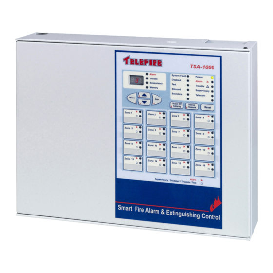
Conventional Multi-Zone Fire Alarm and Extinguishing Control Panel
Brand:
Telefire
| Category:
Control Panel
| Size: 1 MB
Table of Contents
Table of Contents
4
1 Introduction
9
2 Functions and Options
11
En 54-2 Options with Requirements
11
3 Important Notes
12
Manual Triggering
12
Manual Triggering Devices
12
Dependency on more than One Alarm Signal
12
Two Zones Coincidence
13
Note Regarding Default Configuration
14
Maximum Number of Detectors
14
Suitability of Use in Various Environments
14
Limiting the Consequences of Faults
14
Figure 1 TSA-1000 Typical System
15
4 Terms, Definitions and Abbreviations
16
Abbreviations
16
Terms and Definitions
16
5 Safety
17
Grounding and Mains Supply Connection
17
Batteries Handling and Safety
18
6 Access Levels
19
7 Technical Specifications
20
Main Elements, Basic Unit
20
Expansion Modules
20
I/O Functions of the Different Expansion Boards/Modules
20
Relays
20
Tsa-1000C Communication Expansion Module
21
Table of Technical Specifications, TSA-1000
22
Table 1 Technical Specifications
28
Default Ports Allocation and Configuration
29
8 Tsa-1000 Control Panel Assembly
30
Power Supply, Charger and Batteries
30
Figure 2 Module Location
30
Main Board
31
Expansion Modules
31
Activation
31
Front Door
32
Figure 3 Display and Keyboard
33
9 User Interface-Display and Keyboard
34
General Display Area
34
Figure 4 General Display Area
34
Digital Display and Digital Display Indicators
38
Zone Indicators
39
Keyboard
39
Figure 5 Digital Display and Digital Display Indicators
39
Figure 6 Zone Indicators
39
Figure 7 Keyboard
39
10 Work States
41
Normal State
41
Alarm State
41
Fault State
42
Supervisory State
42
Disablement State
43
Test State
43
11 Installation
44
Pre-Installation Planning
44
Mounting
45
Wiring
46
Figure 8 Chassis Mounting Holes
46
Figure 9 Routing High- and Low Voltage Cables in the TSA-1000 Chassis
48
Figure 10 RM-1000 Connection
49
Figure 11 Connecting a Network
49
Installing Detectors, Input and Output Devices, and Other Devices
50
Figure 12 Main Board Connectors
50
Figure 13 Expansion Module Connectors
51
Figure 14 Connecting Two Detectors and a TPB-10R Break-Glass
51
Figure 15 Connecting Programmable and General Sounders
51
Connecting the Mains, Batteries and the Ground Wire
52
Figure 16 Connecting the Grounding Wire to the Chassis
52
Post-Installation
53
Connecting Atdm-500 I Dialer
54
Figure 17 Connecting a TDM-500I Dialer (W/W Rev C5, S/W Rev 2.05.01)
54
12 Extinguishing
56
Automatic Extinguishing
56
Manual Extinguishing
56
Extinguishing Output
56
Emergency Hold and Emergency Abort
56
Post-Activation Indication
56
Actions to Perform after Extinguishing Activation
57
Reestablishing the Quiescent Condition after Extinguishing
57
13 Connecting Extinguishing Equipment
58
Extinguishing Adapters
58
Number of Extinguishing Adapters
58
Extinguishant Quantities
59
Fike Fireraser
59
Figure 18 Connecting a FIRERASER Cylinder for Automatic Extinguishing
59
Fike Gca
60
Greenex Aerosol Containers
60
Figure 19 Connecting a GCA-Activated Extinguishing Cylinder
60
Figure 20 Connecting a Greenex Aerosol Extinguishing Container
60
Firepro Aerosol Containers
61
A Typical Application - Extinguishing and Electricity Disconnect
61
Figure 21 Connecting Firepro Aerosol Generators
61
Figure 22 a Typical Application - Cross-Zone Activation of Electricity Disconnect
62
Evacuation Volume Extinguishing
62
14 Control Panel Programming
63
Menu Structure
63
Entering Programming Mode
63
Key Functions During Programming
63
Figure 23 Programming Menu Structure
63
Display During Programming
64
Programming Sequence
65
Figure 24 the Seven-Segment Display and Representation of Digits and Letters
65
Dialer Programming
66
Horn Output Programming
66
Expansion Card Programming
66
Figure 25 Device Selection
66
Remote Annunciator Programming
67
Network Programming
67
Relay Programming
67
Figure 26 Display During Relay Programming
68
Zone Programming
69
Figure 27 Programmable Relay Contacts During Normal Operations and Upon
69
Output Programming
70
Figure 28 Display During Input Programming
70
Figure 29 Display During Output Programming
71
Saving Data and Exiting Programming Mode
72
15 Operation and Maintenance
73
Evacuation (Evc)
73
On / off Zone or Output (OFF)
73
Field Test (Ft)
73
Event Log (Log)
74
Alarm Counter (Alc)
74
Changing Password (Pas)
74
Setting Time and Date (T+D)
74
Lamp Test (Lt)
75
Additional Information (Inf)
75
Restoring Default Configuration (Def)
75
16 Troubleshooting
76
Maintenance Alert
76
System States
76
System Faults
76
Programming Faults
78
17 Commissioning
80
18 Maintenance
82
19 Routine Testing
83
Advertisement
Advertisement
Related Products
Telefire TSA-200
Telefire TSA-200XT
Telefire TSA-240XT
Telefire TSA-240
Telefire TBD-8100
Telefire TFB-180SA
Telefire TFB-180BSA
Telefire TDM-500i
Telefire ADR-7000
Telefire GUARD-7
Telefire Categories
Security Sensors
Control Panel
Control Unit
Smoke Alarm
Security System
More Telefire Manuals
Login
Sign In
OR
Sign in with Facebook
Sign in with Google
Upload manual
Upload from disk
Upload from URL