Sign In
Upload
Download
Table of Contents
Contents
Add to my manuals
Delete from my manuals
Share
URL of this page:
HTML Link:
Bookmark this page
Add
Manual will be automatically added to "My Manuals"
Print this page
×
Bookmark added
×
Added to my manuals
Manuals
Brands
Hansen Manuals
Industrial Equipment
P4
Installation manual
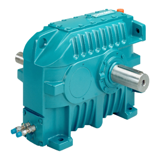
Hansen P4 Installation Manual
Standardized gear units
Hide thumbs
Also See for P4
:
Service manual
(36 pages)
,
Service manual
(47 pages)
,
Service manual
(44 pages)
1
2
Table Of Contents
3
4
5
6
7
8
9
10
11
12
13
14
15
16
17
18
19
20
21
22
23
24
25
26
27
28
29
30
31
32
33
34
35
36
37
38
39
40
41
42
43
44
45
46
47
48
49
50
51
52
53
54
55
56
57
58
59
60
61
62
63
64
65
66
67
68
69
70
71
72
page
of
72
Go
/
72
Contents
Table of Contents
Bookmarks
Table of Contents
Table of Contents
1 Customer Data Sheet
2 Manual Disclaimer
3 About this Document
Function of the Document
Language
Illustrations
Use of Steps, Lists and Titles in this Document
How to Use this Document
Warnings, Cautions and Notes Used in the Document
Related Documents
Storage of this Document and the Related Documents
Abbreviations
Customer Support
4 Description
Intended Use
Type Plate
Signs in the Documentation and on the Gear Unit
Description of the Lubrication of the Gear Unit
Function of Lubrication
Splash Lubrication
Force-Feed Lubrication
Breather Plug
Cooling System
Direction of Rotation of the Shafts
5 Safety
Restrictions
Approved Installation Engineer
General Safety Instructions
Safety Instructions for Installation
Special Safety Instructions (Backstop)
Noise and Vibrations
Partly Completed Machine
Instructions in Case of a Fire
Warranty
6 Transport
Off-Site Transport
On-Site Transport
Lift the Gear Unit
7 Storage
General Storage Instructions
Indoor Storage for Maximum 1 Year
Extended Storage Outdoors for Maximum 2 Years (Extended Outdoor Storage)
Extended Storage Indoors for Maximum 5 Years (Extended Indoor Storage)
8 Installation
Maximum Time between Installation and Commissioning
Remove the Packaging Material
Installation Instructions for Parts that Are Not Part of the Gear Unit
Do a Check for Corrosion of Internal Parts of the Gear Unit
Install the Couplings
Prepare
Apply the Sealing Paste
Install the Coupling Hubs
Remove Unwanted Sealing Paste and Apply Paint
Install Parts that Give External Loads to the Gear Unit
Install Gear Units with a Backstop
Align the Gear Unit
Align the Gear Unit in the Horizontal Plane
Align the LSS (Multi-Stage)
Align the LSS (Single Stage)
Align the HSS
Attach the Gear Unit with the Bolts (Solid Shafts)
Attach the Gear Unit
Install the Safety Cover
Attach the Gear Unit (Hollow Shafts)
Install the Shrink Disk
Install the Shaft with Keyway Connection
Install the Torque Arm
Install a Ground Connection
Install the Lubrication System
General Instructions for the Lubrication System
Instructions for Force-Feed Lubrication (Integrated Pump)
Instructions for Force-Feed Lubrication (Pump with a Motor)
Instructions for Force-Feed Lubrication (Pressure Lubrication)
Fill the Gear Unit with Gear Oil
Select the Gear Oil
Add Gear Oil (Gear Unit with Motor Base)
Add Gear Oil (QHR.4, QVR.3 and QVR.4)
Measure the Gear Oil Level
Add Gear Oil (All Gear Units)
Drain Gear Oil
Add Grease to the Lubrication Points for Grease
Select the Grease Type
Add Grease
Install the Oil-To-Air Cooler
Install the Water Cooling
Install the Oil-To-Water Cooler
Install the Cooling Coils
Installation Instructions (Heater)
9 Commissioning
Maximum Time between Commissioning and Operation
Do a Check on the Gear Unit
Start Instructions (Backstop)
Start Instructions (Heater)
Start Instructions (Force-Feed Lubrication, Pump with a Motor)
Start Instructions (Force-Feed Lubrication, Integrated Pump)
Start Instructions (Drive Group with a 2-Speed Motor)
Instructions after Commissioning
10 Instructions for Operation
General Instructions for Operation
Instructions (Force-Feed Lubrication, Pump with a Motor)
Instructions (Water Cooling)
Instructions (Drive Group with a 2-Speed Motor)
Instructions if the Gear Unit Does Not Operate more than 2 Weeks
Operate the Gear Unit for 5 Minutes each 2 Weeks
Protect the Gear Unit with a Volatile Corrosion Inhibitor
11 Removal of the Gear Unit
General Instructions for Removal of the Gear Unit
Remove the Gear Unit (Solid Shafts, Couplings)
Remove the Gear Unit (Hollow Shafts)
Disconnect the Gear Unit from the Torque Reaction Point
Remove the Shrink Disk
Disconnect the Keyway Connection
12 Care for the Environment
13 Technical Data
Dimensions and Mass
Materials of the Gear Unit
Torque Seal Specification
Paint Specification
Corrosion Protection by H.I.T
Position of the Gear Unit
Ambient Conditions for Storage
Misalignment of the LSS
Misalignment of the HSS (Couplings)
Bolt Specifications (Gear Units with Solid Shafts)
Bolt Specifications (Single-Stage, Horizontal LSS)
Bolt Specifications (Multi-Stage, Horizontal LSS)
Bolt Specifications (Multi-Stage, Vertical LSS)
Torque Values for Oil Drain Screw
Shrink Disk Specifications (2-Part Shrink Disk)
Lubrication
Torque Specifications
Prestress Specifications for the Torque Arm (Hollow Shaft)
Lubricants
General Specifications for Lubricants
Additional Gear Oil Specifications (Heater)
Mineral Gear Oil and Related Grease
Synthetic Gear Oil and Related Grease
Grease Quantity at Lubrication Points for Bearings
Grease Quantity Type
Grease Quantity Types Q1, Q2, Q3, Q6, Q7 and Q8
Grease Quantity Type Q4
Grease Quantity Type Q5
Grease Quantity Type Q9
Grease Quantity for Lubrication Points at Labyrinth Seals (LSS)
Grease Quantity Type
Grease Quantity (Single-Stage)
Grease Quantity (Multi-Stage)
Grease Quantity for Lubrication Points at Labyrinth Seals (HSS)
Grease Quantity Type
Grease Quantity (Single-Stage)
Grease Quantity (Multi-Stage)
Cooling Water Specifications
Advertisement
Quick Links
1
Description of the Lubrication of the Gear Unit
2
Select the Gear Oil
3
Dimensions and Mass
Download this manual
See also:
Service Manual
Installation manual
405
Standardized gear units
Hansen Industrial Transmissions nv
IM_405
Table of
Contents
Previous
Page
Next
Page
1
2
3
4
5
Advertisement
Table of Contents
Need help?
Do you have a question about the P4 and is the answer not in the manual?
Ask a question
Questions and answers
Related Manuals for Hansen P4
Industrial Equipment Hansen P4 Service Manual
Standardized gear units (47 pages)
DC Drives Hansen P4 Series Service Manual
Standardized gear units (44 pages)
Industrial Equipment Hansen APPT08 Specifications, Applications, Service Instructions & Parts
Non-condensible gas (air) & water purger for ammonia (28 pages)
This manual is also suitable for:
405
Table of Contents
Print
Rename the bookmark
Delete bookmark?
Delete from my manuals?
Login
Sign In
OR
Sign in with Facebook
Sign in with Google
Upload manual
Upload from disk
Upload from URL
Need help?
Do you have a question about the P4 and is the answer not in the manual?
Questions and answers