
Related Manuals for BADU BNR 300


Summary of Contents for BADU BNR 300
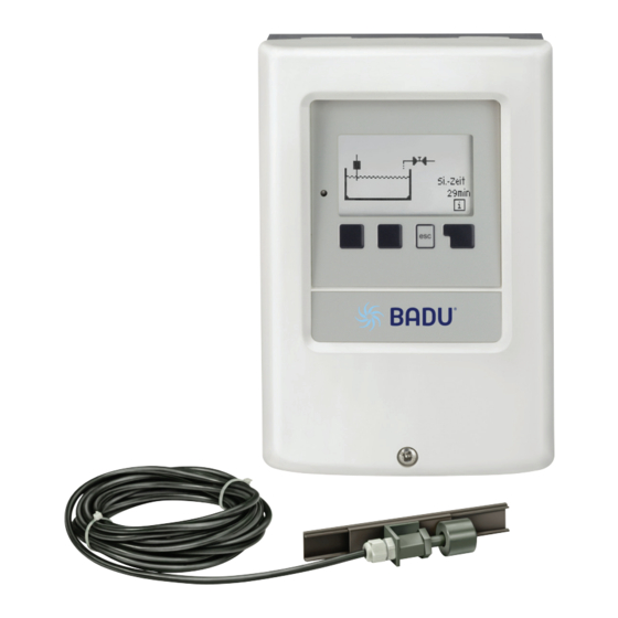
- Page 1 Level controller BADU BNR 300 ® Installation and operating instructions Read carefully before installation, commissioning and operation...
-
Page 2: Table Of Contents
Inhalt page A.1. EC declaration of conformity 4.11. Filling A.2. General instructions 4.12. Signal switch 1 A.3. Explanation of symbols 4.13. Signal switch 2 A.4. Changes to the unit 4.14. Signal switch 3 A.5. Warranty and liability Protective functions B.1. Specifications 5.1. -
Page 3: Ec Declaration Of Conformity
Safety instructions A.1. EC declaration of conformity By affi xing the CE mark to the unit the manufacturer declares that the BADU ® BNR 300 conforms to the EC low voltage directive 2006/95/EC and the EC electromagnetic compatibility directive 2004/108/ Conformity has been verifi ed and the corresponding documentation and the EC declaration of confor- mity are kept on fi le by the manufacturer. A.2. General instructions These installation and operating instructions contain basic instructions and important infor- mation regarding safety, installation, commissioning, maintenance and the optimal use of the unit. -
Page 4: Changes To The Unit
Safety instructions A.4. Changes to the unit Changes to the unit can compromise the safety and function of the unit or the entire system. • Changes, additions to or conversion of the unit are not permitted without written authorisati- on from the manufacturer •... -
Page 5: Specifications
Description of controller B.1. Specifications Electrical specifications: Mains voltage 230 VAC +/-10 % Mains frequency 50 - 60 Hz Power consumption 1.5 W - 2.3 W Internal fuse 2 A slow blow 250 V Protection category IP 40/IP 44 (only with the supplied gasket set) Protection class Overvoltage category Degree of pollution category mechanical relay 460W maximum AC3... -
Page 6: About The Controller
BNR 300 level controller enables an automatic level control for your swimming pool. The device is impressive most of all for its functionality and simple, almost self-explanatory ope- ration. For each step in the input process the individual entry keys are assigned to appropriate functions and explained. The controller menu contains headwords for the measured values and settings as well as help texts or clearly-structured graphics. The BADU ® BNR 300 can be used as a solar controller for the various system variants illustrated and explained under “B.6. Hydraulic variants” on page 7. Important characteristics of the BADU ® BNR 300: Depiction of graphics and texts in an illuminated display Simple viewing of the current measurements Analysis and monitoring of the system by means of statistical graphics, etc. -
Page 7: Hydraulic Variants
Description of controller B.6. Hydraulic variants The following illustrations should be viewed only as schematic diagrams showing the respective hydraulic systems and do not claim to be complete. The controller does not replace safety devices under any circumstances. Depending on the specifi c application, additional system components and safety components may be required, such as check valves, non-return valves, safety temperature limiters, scalding protectors etc. and must therefore be provided. -
Page 8: Wall Installation
Installation C.1. Wall installation Install the controller in dry areas only and under the ambient conditions described un- der “B.1. Specifi cations”. Follow the instructions below: 1. Unscrew cover completely C.1.1 . 2. Carefully pull upper part of housing from lo- wer part. Terminal clamps are released during this process. -
Page 9: Electrical Connection
Installation C.2. Electrical connection Before working on the unit, switch off the power supply and secure it from being switched on again! Check for the absence of power! Electrical connections may only be made by a specialist and in compliance with the applicable regulations. Do not use the controller if the housing shows visible damage, for example cracks. Low-voltage cables such as temperature sensor cables must be routed separa- tely from the mains voltage cables. Feed temperature sensor cables into the left- hand side of the unit only and mains voltage cables into the right-hand side only. -
Page 10: Installing The Water Detectors
Installation 1. Select necessary programme/hydraulics. C.2.1. 2. Open controller casing (“C.1. Wall installa- tion” on page 8). 3. Strip cables by 55 mm, insert, fi t the strain relief devices, strip the last 8-9 mm of the wires. (Fig. C.2.1.). 4. Open the terminals using a suitable screwdriver (Fig. C.2.1.) and make electri- cal connections on the controller. 5. Refi t terminal connection cover and fasten screw. -
Page 11: Terminal Connection Diagram
Installation D. Terminal connection diagram Low voltage Relay Mains Mains voltage 230 VAC max. 12 V Low voltage max. 12 VAC/DC Mains voltage 230 VAC 50-60 Hz Terminal: Connection for: Terminal: Connection for: S1 (2x) Level switch Magnet valve (alarm signal) N S2 (2x) Level switch 1/water detector R1 Magnet valve (alarm signal) L S3 (2x) Level switch 2/water detector Mains neutral conductor N -- (2x) not used Mains phase conductor L... -
Page 12: Display And Input
Operation E.1. Display and input The display (1), with its extensive text and graphics mode, is almost self-explanatory, allowing easy operation of the controller. Inputs are made with 4 buttons (3+4), which have different functions depending on the con- text. The “esc” key (3) is always used to cancel or exit a menu. If applicable there will be a request for confir- mation as to whether the changes which have been made should be saved. The function of each of the other three keys (4) is shown in the display line directly above the keys; the right-hand key generally has a Examples of display symbols: confirmation and selection function. -
Page 13: Commissioning Help
Commission E.2. Commissioning help The fi rst time the controller is turned on and after the language and time are set, a query appears as to whether you want to parametrise the controller using the commissioning help or not. The commis- sioning help can also be terminated or called up again at any time in the special functions menu. -
Page 14: Menu Sequence And Menu Structure
Operation E.4. Menu sequence and menu structure The graphics or overview mode appears when no key has been pressed for 2 minutes or when the main menu is exited by pressing the “esc” key. Pressing a key in the graphics or overview mode will lead directly to the main menu. Here the following menues are available: Current values with explanations 1. Measurements Function control of the system with operating 2. -
Page 15: Measurements
Measurements 1. Measurements The menu “1. Measurements” serves to display the actual water level and water detectors. The menu is closed by pressing the “esc” key or selecting “Exit Measurements”. -
Page 16: Statistics
Statistics 2. Statistics The menu “2. Statistics” is used for function control and long-term monitoring of the sys- tem. The menu is closed by pressing the “esc” key or selecting “Exit statistics”. For analysis of the system data it is essential for the time to be set accurately on the controller. Please note that the clock only has a battery reserve for 24 hours and must therefore be reset afterwards. Improper operation or an incorrect time may result in data being deleted, recorded incorrectly or overwritten. -
Page 17: Operating Mode
Operating mode 3. Operating mode In the menu “4. Operating mode” the control- ler can either be placed in automatic mode, switched off or placed in a manual operating mode. The menu is closed by pressing the “esc” key or selecting “Exit operating mode”. 3.1. Automatic Automatic mode is the normal operating mode of the controller. Only automatic mode provides proper controller function taking into account the current position of the level switch/es and the parameters that have been set! After an interruption of the mains voltage the controller automa- tically returns to the last operating mode selected! -
Page 18: Settings
Settings 4. Settings The necessary basic settings required for the con- trol function are made in the menu “5. Settings”. This does not under any circumstan- ces replace the safety facilities to be provided by the customer! The menu is closed by pressing the “esc” key or selecting “Exit settings”. The menu numbering can alter depending on the selection of hydraulic variant (see “7.1. Program selection” on page 26). -
Page 19: Impulse Off-Time
Settings 4.3.4. Impulse off-time Impulse off-time in seconds for the additional relay in safety operation and impulse mode. Setting range: 3 ... 30/Default: 10 4.3.5. Unit of dry run protection Unit for the dry run protection. Setting range: Seconds, Minutes/Default: Minutes. 4.3.4. -
Page 20: Filling
Settings 4.11. Filling This menu is used to set the daily filling time. This ensures that filling is only carried out for the time set here each day. Up to three filtering times can be set each day and copied to another day. Therefore filling at night can be avoided. Setting range: off, daily 0:00 - 23:59/Default: daily 6:00 - 22:00 4.12. Signal switch 1 The level switch mode can be set here depending on the type and use of the level switch. In normal mode, the contact of the level switch is closed when the level switch is down. -
Page 21: Protective Functions
Protective functions 5. Protective functions The menu “6. Protective functions” can be used to activate and set various protective functions. This does not under any circumstances replace the safety facilities to be provi- ded by the customer! The menu is closed by pressing the “esc” key or selecting “Exit protective functions”. If the safety shutdown has been triggered, the red LED and the display’s back- ground lighting fl ash. To reset the safety shutdown system press and hold the middle two buttons for three seconds. 5.1. -
Page 22: Mode Water Detector
Protective functions 5.5. Sensitivity water detector 2 Depending on the type and model the switching threshold of the detector can be set here. The aging of the contacts and the appearance of deposits may lead to a readjustment of the con- tacts being necessary. -
Page 23: Special Functions
Special functions 6. Special functions The menu “7. Special functions” is used to set basic items and expand functions. Other than the time, all settings may only be made by a specialist. The menu is closed by pressing the “esc” key or selecting “Exit special functions”. 6.1. Program selection The suitable hydraulic variant for the specifi c application is selected and set here (see “B.6. Hydraulic variants” on page 7). The associated diagram is displayed after pressing “Info”. Setting range: 1 - 6/Default: 1 Normally the program selection is made only once during initial commissioning by the specialist. -
Page 24: Time And Date
Special functions 6.4. Time and date This menu is used to set the current time and date. For analysis of the system data it is essential that the time is set accurately on the controller. Please note that the clock has a 24 hour battery reserve if the mains voltage is interrupted and must therefore be reset afterwards. 6.5. -
Page 25: Service Values
Service values 8. Service values The menu “8. Service values” can be used for remote diagnosis by a specialist or the manu- facturer in the event of an error. Enter the values at the time when the error occurs e.g. in the table. The menu can be closed at any time by press- ing the “esc” key. -
Page 26: Malfunctions With Error Messages
Malfunctions Z.1. Malfunctions with error messages If the controller detects a malfunction, the red light fl ashes and the warning symbol also appears in the display. If the error is no longer present, the warning symbol changes to an (LED fl ashes + info symbol and the red light no longer fl ashes. warning symbol) To obtain more detailed information on the error, press the key under the warning or info symbol. -
Page 27: Replacing The Fuse
Malfunctions Z.2. Replacing the fuse Repairs and maintenance may only be performed by a specialist. Before wor- king on the unit, switch off the power supply and secure it from being switched on again! Check for the absence of power! Only use the spare fuse supplied or a fuse of the same design with the following specifi cations: T 2 A/250 V If the mains voltage is switched on and the Z.2.1. - Page 28 ‚ Commissioner‘s notes: Hydraulic variant set: Commissioned on: Commissioned by: Final declaration: Although these instructions have been created with the greatest possible care, the possibility of incorrect or incomplete information cannot be excluded. Sub- ject as a basic principle to errors and technical changes.
Need help?
Do you have a question about the BNR 300 and is the answer not in the manual?
Questions and answers
comment réinitialiser le régulateur d eau de la piscine
To reset the BADU BNR 300 pool water regulator after a safety shutdown, press the two middle buttons simultaneously for 3 seconds.
This answer is automatically generated