
Related Manuals for Talgil DREAM 2


Summary of Contents for Talgil DREAM 2
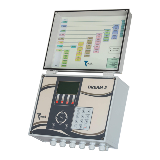
- Page 1 TALGIL COMPUTING & CONTROL LTD. NAAMAN CENTER, HAIFA - ACCO ROAD ISRAEL P.O. BOX 775 KIRYAT MOTZKIN 26119 TEL: 972-4-8775947 - 8775948 FAX: 972-4-8775949 DREAM 2 WIRED RTU SYSTEM GUIDE 2007...
-
Page 2: Table Of Contents
CONTENTS 1. SYSTEM OVERVIEW ....................... 3 THE PARTS OF THE SYSTEM AND THEIR FUNCTION ............3 2. INSTALLATION DIRECTIONS ....................4 CABLE TESTING ........................4 GROUND CONNECTIONS ...................... 4 SETTING THE ADDRESSES ....................4 DEFINITIONS TO BE MADE INSIDE THE DREAM ..............5 DECLARING THE 2W RTU INTERFACE .............. -
Page 3: System Overview
THE TWO WIRED SINGLE CABLE SYSTEM OF THE DREAM 1. SYSTEM OVERVIEW The DREAM TWO WIRED SINGLE CABLE SYSTEM utilizes Remote Terminal Units for connecting remote valves and distant meters to the control system covering territories of up to 10 Km radius by use of 2 wired cables. The Remote Terminal Units (RTU) have the ability to communicate with the DREAM, to carry out the received commands and to report back the status of the meters connected to them. -
Page 4: Installation Directions
2. INSTALLATION DIRECTIONS Wiring must be done while the system is not energized. Remember to disconnect both the charger/solar- panel and the rechargeable battery. CABLE TESTING Prior to connecting the 2 wired line to the RTUs and to the DREAM they must be checked as explained in appendix "B". -
Page 5: Definitions To Be Made Inside The Dream
unique address and in order for the "2W RTU interface" to be able to differentiate between the various RTUs, each RTU must have it's own address. So each output and input in the 2 wired system will have it's location defined by 3 numbers: II;RR;L – "II" is the address of the interface, "RR"... -
Page 6: Checking Communication With The Rtus
2.4.3 CHECKING COMMUNICATION WITH THE RTUs The fifth screen to the right in the subject of "CURRENT STATUS" shows the quality of communication with each of the 2W RTUs. An RTU with communication problem will be underlined. There are 17 RTUs. No 16,17 not responding The address of the 2W RTU interface... -
Page 7: Setting The Addresses Of The Digital And Analog Inputs
The system can handle analog inputs as well. There are "plug in" modules of 2 analog inputs that can be used in place of each module of 4 digital inputs, using the same sockets. Therefore, each analog inputs module reduces the number of left digital inputs of that RTU by 4. Analog inputs Possible digital inputs Up to 8... -
Page 8: The Leds And The Buzzer Indications
3.1.3 THE LEDS AND THE BUZZER INDICATIONS Green LED blinking slowly - After resetting the RTU, there is a delay before starting capacitor charging. delay depends on the RTUs address, and it is calculated by the RTU's address multiplied by 2. During the delay, there will be slow blinking of the green led. -
Page 9: Compact Rtus
COMPACT RTUS The compact RTUs can handle up to 2 outputs and 2 digital inputs or alternatively 1 analog input can be requested in place of the two digital ones. Reset button Plug for communication with the utility software I/O test I/O test I/O test button... -
Page 10: The Leds And The Buzzer Indications
3.2.1 THE LEDS AND THE BUZZER INDICATIONS The LEDs and the buzzer indications of the compact RTU are similar to the modular RTU. However there is a special ticking sound that can only be heard in the compact RTU which has digital inputs defined. -
Page 11: Appendix "A" - Decimal To Binary Convertion
Appendix "A" – DECIMAL TO BINARY CONVERTION In the following table a switch ON is marked by 1 and a switch OFF by 0. Decimal address Binary value set by the Dip Switch Positions: 1 2 3 4 5 6 1 0 0 0 0 0 0 1 0 0 0 0 1 1 0 0 0 0... -
Page 12: Appendix "B" - About The Cable
Appendix "B" – ABOUT THE CABLE ABOUT THE CABLE TO BE USED Recommendations for the cable to be used with the 2 wired systems: Never mix in one cable two lines of separate 2w channels. Never mix in the same cable a 2 wired channel and an RS485 communication line. Always maintain a distance of at least 20 cm between the cables of different 2W channels and RS485 when laid in the ground. -
Page 13: Appendix "C" - Testing Procedure
Appendix "C" – TESTING PROCEDURE TESTING PROCEDURE OF THE 2W SYSTEM The 2W interface has three main functions: 1. Supplying energy to all the RTUs in the system. 2. Scanning all the RTUs second by second. 3. Exchanging information with the DREAM second by second. The 2 wired cable originating from the 2W interface and arriving to all the RTUs, carries both the energy and the communication to the RTUs. -
Page 14: Appendix "D" - Multiple Interfaces Wiring
Appendix "D" – MULTIPLE INTERFACES WIRING Wiring of a DREAM system which is powered by AC and which contains multiple 2 wired interfaces Rechargable DREAM ++2W battery P.S. AC/DC 7 Ah 12V Remote P2N2 +12V- 12 V- Int 2W. Repeater 12 V- To DR .
Need help?
Do you have a question about the DREAM 2 and is the answer not in the manual?
Questions and answers