
Related Manuals for Talgil DREAM 2


Summary of Contents for Talgil DREAM 2
- Page 1 TALGIL COMPUTING & CONTROL LTD. NAAMAN CENTER, HAIFA - ACCO ROAD ISRAEL P.O. BOX 775 KIRYAT MOTZKIN 26119 TEL: 972-4-9506050 - 9506051 FAX: 972-4-8775949 DREAM 2 INSTALLATION GUIDE February 2016...
-
Page 2: Table Of Contents
Table of Contents THE SYSTEM STRUCTURE ........4 Looking inside the DREAM 2 case ..............5 1.1.1 The Power Supply board..................7 1.1.2 The Mother Board ....................8 1.1.3 The CPU board ....................9 SWITCHING UP AND SHUTTING DOWN ....10 Switching Up .................... - Page 3 9.3.1 The Push Buttons ..................... 59 9.3.2 LED indicators ....................59 9.3.3 The Jumper ...................... 59 APPENDIXES ............60 Appendix “A” – Decimal to Binary conversion ........60 10.1 Appendix "B" – Rules about cables ............61 10.2 10.2.1 CABLE RESISTANCE TESTING..............61...
-
Page 4: The System Structure
SERVER. Users and technicians can now access the controllers from everywhere anytime. Upgrading from DREAM 1 to DREAM 2 is involved with replacement of three boards only: the CPU, the Mother board and the Power supply board. -
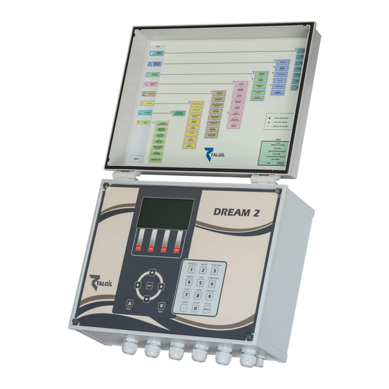
Page 5: Looking Inside The Dream 2 Case
The schematic drawing above shows the various kinds of Interfaces recognized by the DREAM 2 system. A control system will include an arbitrary combination of these Interfaces; some controllers may include several Interfaces of the same type. - Page 6 The picture above shows the inner part of a DREAM 2 controller. It must be pointed out that due to the flexible structure of the DREAM 2 system, the construction of a controller may vary from one case to another, depending on the specific needs.
-
Page 7: The Power Supply Board
1.1.1 The Power Supply board Charge voltage Charge limit Outputs current Main power fuse adjust resistor sampling resistor Charging fuse 12v DC fuse Power switch Charging 24 v AC Start button 12 v DC Charging 12 v DC The drawing above shows the two options of power supply boards. The one on the left is the DC type, it is used for powering from solar energy and the one on the right is the AC type to be used for powering from the mains. -
Page 8: The Mother Board
At the right side there are two green sockets from which 12v DC can be obtained. This voltage is available after the Start Button has been pushed and as long as the DREAM 2 application has not been shut down by the Shut Down command. -
Page 9: The Cpu Board
The USB socket can be used for connecting USB memory sticks for uploading/downloading the image files into the controller or for updating the software version. Another use of the USB socket will be for connection of a Netsctick for cellular communication (see below). In case the communication is meant to be through the Ethernet or LAN (Local Area Network), the two Ethernet sockets will be used. -
Page 10: Switching Up And Shutting Down
ADMINISTRATION software) about the new CPU that replaces the old one. SWITCHING UP AND SHUTTING DOWN 2.1 Switching Up Switching up the DREAM 2 from a switched off state is done in 2 steps: 1. Turning ON the Power Switch. 2. Pushing the Start button. -
Page 11: Shutting Down
2.2 Shutting Down The internal structure of the DREAM 2 is very much like the structure of a desktop personal computer that has an operating system which handles multiple applications simultaneously. This kind of activity is naturally involved with opening of multiple files as required by the active applications. -
Page 12: The Internet Communication
THE INTERNET COMMUNICATION The DREAM 2 has 3 options for accessing the internet: Using a Cellular Modem supplied by Talgil and plugged into the CPU board. Using an Ethernet card for connecting to a Local Area Network. Using a USB Netstick plugged into the motherboard. -
Page 13: Communication Through Ethernet
3.1 Communication through Ethernet Step 1- Enter the System Manager screens by pressing the PgDn (˅) and PgUp (˄) keys simultaneously. Step 2- While the cursor is placed on the General subject use the right arrow to move the cursor to the right side of the screen and then use the down arrow to move the cursor to the Connection row. - Page 14 The Dealer’s user name Step 6- The IP address (DNS) of the Server is srv.talgil.com and the port to be used is 55300. If the IP address is incorrect and has to be changed, bring the cursor to the existing address and press the Enter key, as a result the screen will change into an editor screen like the one below, in which the characters need to be selected one by one.
-
Page 15: Communication Through Modem Or Netstick
The success or failure of connection can be checked at the following screen which can be reached from the Main menu by hitting F2=About. To get back to the Main menu push the PgDn (˅) and PgUp (˄) keys simultaneously. Successful connection The connection process may take some time, however if it fails we can always try to use... -
Page 16: The System Management Screens
The System Management screens are usually hidden, but can be reached from any of the DREAM 2 application screens by pushing simultaneously the PgDn (˅) and PgUp (˄) buttons. Same two buttons will be used later on for getting back into the DREAM 2 application screens. -
Page 17: Network
(see above). At the system management screens the clock is presented as a 24 hours clock, inside the DREAM 2 application it depends on the selected language, if it is English US, the clock will be in AM/PM. The LCD turn off time –... - Page 18 The IP address – This is the address given for the DREAM 2 within the router, or in other words, this is the address at which the controller can be found on the Internet. The GW (GateWay address) –...
-
Page 19: Logging
If this field is left undefined, the controller will be registered as belonging to Talgil and in order for a Dealer to be able to use it, he shall have to contact Talgil and ask for the controller to be moved to his account. -
Page 20: Update
The stages of the update procedure will be indicated on the LCD display. The update procedure takes a couple of minutes and at the end success or failure will be declared. A few seconds later the display will show the main menu of the DREAM 2, ready for use. - Page 21 The main menu of the DREAM 2 controller The software update from USB requires two files: gdreamSetxy.md5 and gdreamSetxy.tar where “xy” represent the version number. The system will look for those files in the folder called tlgupdate on the root directory of the memory stick.
-
Page 22: Modem
The VPN acts like a bypass to the regular communication channel, which is used by the technicians in case of need. Activating the VPN should only be done by request from the technical team of Talgil. 4.6 Modem This subject deals with the definitions required for cellular modem communication. It can be accessed only when the Modem communication was selected (see 4.1... -
Page 23: System
4.7 System This subject is supplying information for the use of the technical staff of Talgil. THE VARIOUS I/O OPTIONS The following chapter describes the various I/O options including the various I/O interfaces, I/O boards and RTUs recognized by the DREAM system: 5.1 Interface for local I/O AC or DC... -
Page 24: I/O Expansion And Remote I/O
When having a large number of local Inputs or Outputs we have to take into consideration that the Motherboard of the DREAM 2 may accommodate one interface and no more than two local I/O boards, therefore the maximum number of outputs, and inputs inside the enclosure is limited to 2x16=32 outputs and 2x8=16 digital inputs. - Page 25 The following pictures show the connection between the DREAM 2 and the I/O expansion unit. The connection is by a 2 wired cable connected between the remote I/O RS485 terminals on the two motherboards. In case the I/O expansion unit is installed far from the...
- Page 26 The maximal length of the cable from the I/O board to the sensor should not be longer than a few meters. Inputs terminal Inputs terminal block block Outputs Outputs terminal terminal block blocks The inputs’ The outputs’ The outputs’ The inputs’ common is common is common is...
-
Page 27: Interface For Single Cable 2 Wired Rtus
The 2 wired line is used both for communication and for supplying energy to the RTUs from the 2W interface. Up to 60 RTUs may be connected to a 2W interface. The DREAM 2 may handle several 2W interfaces. -
Page 28: Interface For Radio Communicated Rtus
GENERATION III IV and IV.V”. 5.4 Interfaces for local analog inputs As mentioned above, analog inputs can be read both through the 2W RTU system and the RF RTU system, however analog sensors located in the close vicinity of the DREAM 2 controller can... - Page 29 4 analog inputs. In the first drawing the interface is plugged into the motherboard and the sensors are powered by the 12v from the motherboard. In the second drawing the interface is installed outside the enclosure of the Dream 2 and both the sensors and the interface are powered externally.
-
Page 30: Interface Ph/Ec (Fertmaster)
During the injection process, it receives from the DREAM 2 controller all the details and the requirements of the particular process and it executes the injection accordingly. All along the injection process, the DREAM 2 is updated continuously about the status and the results. -
Page 31: Thd Interface
Detailed information about the pH/EC Interface can be found in the manual “FERTMASTER pH/EC USER GUIDE 2007”. 5.6 THD Interface The THD interface is meant to measure the ambient Temperature and Humidity, calculate the actual Dew point and report the three values back to the controller. The values can then be used for frost protection or conditioning of cooling programs. -
Page 32: Weather Station Interface
5.7 Weather station Interface The Weather station interface enables connection of a “Davis - Vantage pro2” weather station to the system. The weather station supplies the controller the following data: 1. Barometric pressure 2. Ambient temperature 3. Humidity 4. Wind speed 5. -
Page 33: Lightning Protection
In the DREAM 2 there can be several cases where long cables will require lightning protection: The DREAM++2W - the 2 wired line, can be kilometers long, the RS485 communication line between the DREAM and remote interfaces can sometimes be very long and the DREAM AC may also have long wires between the AC I/O boards and the solenoids. -
Page 34: Lightning Protection For The 2W Single Cable System
6.1 Lightning protection for the 2W single cable system Cable coming Cable going to from the field the 2W interface Ground 6.2 Lightning protection for RS485 communication line Ground 6.3 Lightning protection for 16 AC outputs Cables going to I/O AC board Cables coming Ground... -
Page 35: The Enclosures Of The Dream System
100 percent protection in any case. There is no protection against a direct hit; the energy of the lightning is too high to be absorbed by any protection system. 6.4 The enclosures of the DREAM system The DREAM 2 controllers can be ordered in one of the two enclosure formats: PLASTIC ENCLOSURE METAL CABINET... -
Page 36: Mounting The Controller
Defining the constant parameters. Setting up and testing the internet communication. Teaching the user how to use the system. Any connection or disconnection of components to the system must be done only while the power switch is turned OFF, otherwise unpredictable damage might be caused. -
Page 37: Defining The Configuration
DREAM’S control panel or by using the DREAM simulation software that simulates the DREAM controller on the PC. When done by the simulation software, the resulting configuration file can be loaded into the DREAM 2 controller through the USB socket as explained above in paragraph 4.5 or through the internet by executing the “Upload image file”... - Page 38 L1 – L8. Lines L1 to L6 are irrigating field crops, line L7 is a nursery, and L8 irrigates a palm plantation. The DREAM 2 control unit will be located at the pump house at source "A" where electricity is available. The accessories that are in close proximity with the DREAM 2, will be wired directly to the local I/O terminal boards at the DREAM 2 itself.
- Page 39 Water Free Local Fert Local Fert Water source "A" water site of line 5 source "B" site of line 6 meter Satllite Contact of level sensor Dream Central Source filter site water meter Central fertilizer site Remote Main valve of line 2 Plantation RADIO RADIO...
-
Page 40: The Network Definition
7.2.1 The network definition The network definition process consists of a series of screens through which the contents and the structure of the network is defined. The screens are arranged in a vertical order. Use the PAGE DOWN () and PAGE UP () keys to move between the screens. - Page 41 Water meters that not associated with irrigation lines In our example there are two contacts C1 and C2 used as level sensors of source “A” Analog inputs supply a whole range of values presented as 4-20 mA or 0-5 v. Not implemented in our example When Fert.
- Page 42 Lines 1 to 4 are The number of using central filter valves of line 1 is 6 site No 1 Lines 5 and 6 have Lines 1 to 4 are local fertilizer sites using central fertilizer site No. 1 Line 8 has got a pressure sensors In the next step we define the connection between irrigation lines, water meters, main valves and water sources.
- Page 43 Next step is the definition of the fertilizer sites. For each site, the number of injectors has to be defined and for each injector the existence of fertilizer meter and the existence of connection to a booster pump need to be defined. Central fert site No 1 and the local fert sites of line 5 and line 6 contain 2 injectors, each injector is equipped with fert meter and uses no booster...
-
Page 44: The Hardware Definition
Use the PAGE DOWN () key to reach the following table: Interface DC No1 (resides inside the DREAM 2 enclosure), has 1 I/O board 16/8 (16 outputs, 8 inputs) Interface DC No2 (resides in the REMOTE I/O unit), has... -
Page 45: Connections Definition
As explained above at paragraph 5.1 the local I/O DC/AC interfaces can drive 1 or 2 I/O boards, a single I/O board contains 16 outputs and 8 inputs (16/8) and 2 I/O boards will contain 32 outputs and 16 inputs (32/16). Therefore when defining local I/O interface DC or AC we need to specify whether it is for 16/8 or 32/16 outputs and inputs. - Page 46 Onboard location number Interface address Valve 1 of line 8 by radio interface 4 RTU 1 output 1 Filter 4 by interface 1 output 8 Valve 6 of line 6 by interface 3 (2 wired), RTU 16, output 2. Valve 1 of line 7 by interface 2 (REMOTE I/O), output 1, without RTU.
- Page 47 When finished defining the connections of the outputs we continue with the connections of the digital inputs. The water meter of source B by interface 3 (2 wired) RTU 17 input 1 Fert meter 1 of Central site 1 by interface 1 (Local I/O) input 3, no RTU.
-
Page 48: Testing Operation Of Inputs And Outputs
7.3 Testing operation of inputs and outputs Let us assume that all the outputs and inputs were properly connected according to the connections table described above. However before all the outputs and all the inputs were tested one by one we cannot be sure that they are all functioning as expected. In this document we explain how to carry out the testing through the local MMI of the controller. -
Page 49: What Comes Next
For example, water meters and fertilizer meters need to have their ratio defined; irrigation valves need to have their nominal flow and filling time defined. Both of the two subjects are covered in details in the “DREAM 2 USER GUIDE 2016”. -
Page 50: The Dream Simulation Software
THE DREAM SIMULATION SOFTWARE The DREAM SIMULATION SOFTWARE is a program that enables simulating the DREAM on the PC. The simulation software is a very useful tool for demonstrating, training, experimenting and checking problems. The simulation software will login into the SERVER and then it becomes accessible through the CONSOLE or the SPOT. -
Page 51: Supplementary Devices
The DREAM simulation may also be used for defining a new configuration that can be saved in a configuration file that can later be loaded into the DREAM controller. SUPPLEMENTARY DEVICES In this chapter we shall describe some devices that are used in the DREAM 2 system in special cases. 9.1 Switching electric pumps... - Page 52 The switching units with command of 12v DC latching can be commanded either by three wired command or two wired command. All types of switching units act like a relay that when activated they let the power through and when deactivated they cut off the power from the load. In any case, the power to be switched comes from external source and not generated internally by the unit.
-
Page 55: The Three Functions Of The Rebran Board
IMPORTANT: It is important to point out that unlike the AC type pump-switching units, the DC type units require a power supply of 12v DC without which they would not function. When the pump-switching unit is commanded by the local I/O of the DREAM or the remote I/O expansion unit, the 12v can be taken from the power supply of the DREAM or of the expansion unit. -
Page 56: Or 4 Analog Inputs Interface
galvanically disconnected. This feature helps to solve problems created by leaking communication lines. Repeaters may be needed in two cases: 1. When the RS485 line gives poor results and the signal needs strengthening. 2. When the system contains several 2 wired channels and we want to isolate each channel from the others. -
Page 57: Rs485 Bridge
The board can be plugged into the motherboard directly or connected remotely through the remote I/O RS485 channel. When installed remotely the board requires 12v DC for energizing and 2 wires for the RS485 communication. The board enables reading up to 4 analog inputs of 4-20 mA or 0-5v. Each DIP switch of S2 when set in upper position indicates 4-20 mA input. - Page 58 "x" input pulses counted. The number “x” is based on the selected setting. A special case is when “x” equals 1, then for each pulse received at the input there will be one pulse generated as output. The width of the positive and negative parts of the pulse will be no less than 1 second.
-
Page 59: The Push Buttons
9.3.1 The Push Buttons There are 3 push buttons with the following functions: Reset button- restarts software. Indicator button-changes the function of the indication LEDs (explained below) Test relay button-turns the output relay ON and OFF repeatedly 9.3.2 LED indicators There are 2 LED indications, the RED LED represents the input and the GREEN LED represents the output. -
Page 60: Appendixes
APPENDIXES 10.1 Appendix “A” – Decimal to Binary conversion In the following table a switch ON is marked by 1 and a switch OFF by 0. Decimal Binary value set by Decimal address Binary value set by address Switch Dip Switch Positions: Positions: 1 2 3 4 5 6 1 2 3 4 5 6... -
Page 61: Appendix "B" - Rules About Cables
10.2 Appendix "B" – Rules about cables The following rules must be obeyed when using long cables in the DREAM system: Never mix in the same cable two lines of separate 2w channels. Never mix in the same cable a 2 wired channel and an RS485 communication line. Always maintain a distance of at least 20 cm between the cables of different 2W channels and RS485 when laid in the ground.
Need help?
Do you have a question about the DREAM 2 and is the answer not in the manual?
Questions and answers