Advertisement
Table of Contents
Advertisement
Table of Contents

Related Manuals for Talgil FILTRON 1-10 DC


Summary of Contents for Talgil FILTRON 1-10 DC
- Page 1 TALGIL Computing & Control Ltd. ISRAEL TALGIL COMPUTING & CONTROL LTD. NAAMAN CENTER, HAIFA - ACCO ROAD 7000 P.O.BOX 775 KIRYAT MOTZKIN 26119, ISRAEL TEL: 972-4-8775947; 972-4-8775948 FAX: 972-4-8775949 E-mail: talgil33@netvision.net.il FILTRON 1-10 (DC/AC) U S E R ' S...
-
Page 2: List Of Features
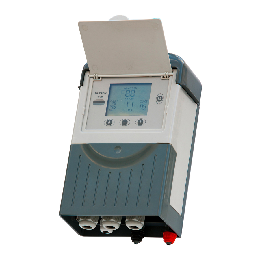
FILTRON 1-10 (DC/AC) List of features The “FILTRON 1-10” is a modular backflushing controller for automatic filters of 1 to 10 stations. There exist DC and AC models. The DC model can be powered either by 6v DC or 12v DC and it activates 2 wired 12v DC latching solenoids. - Page 3 How to program the controller The controller is equipped with an LCD display and 4 keys as displayed below. When the unit is left untouched for a minute the display is switched off and the only life signal is given by a beep sound that can be heard every 20 seconds.
- Page 4 The Flush Time Defines the duration of the flushing time per station. The following options are selectable: 5-20 sec in steps of 1 sec 20-55 sec in steps of 5 sec min in steps of 0.5 min The DP Set Point At this field the user defines the pressure difference between the filter’s inlet and outlet that when reached, a flushing cycle will take place.
- Page 5 The unit will detect how many “plug-in” boards (each of 2 outputs) are used in the particular case. How will the outputs be allocated depends on the definitions made during the configuration process described below. The following rules apply: Backflush valves will be allocated starting from output 1 and up. The last backflush valve can be canceled and then its allocated output will be left unused.
- Page 6 Handling Endless Looping problems As explained above, endless looping problem will be declared when the number of consecutive flushing cycles triggered by the DP sensor exceeds the “Looping limit” defined during configuration. The fact that endless looping problem was detected will be indicated on the display and will cause the activation of the Alarm output, additionally, the DP indication will no longer be considered as a trigger for flushing.
-
Page 7: Timing Diagram
Timing Diagram Without Delay Valve Main valve Flush time Dwell Valve 1 Dwell time Valve 2 Valve 3 Valve 4 Including Delay Valve Main valve Dwell Valve 1 Dwell time Valve 2 Valve 3 Valve 4 Flush time Delay valve Valve Delay... -
Page 8: Wiring Diagram
Wiring Diagram DC MODEL The drawing below shows the wiring of the DC model of the controller. Notice that: The External DP sensor is optional and it is intended for use in cases there is no Embedded Electronic DP included. The powering of the unit can be either by 6v DC or 12v DC. - Page 9 AC MODEL The drawing below shows the wiring of the AC model of the controller. Notice that: The External DP sensor is optional and it is intended for use in cases there is no Embedded Electronic DP included. The powering of the unit is by 24VAC transformed from 220/110 VAC. The solenoids will be of 24VAC.
-
Page 10: Technical Data
TECHNICAL DATA DC MODEL 6v supplied by 4 x 1.5 “D” size alkaline batteries. Power source: or 12v DC dry battery or 12v rechargeable battery with solar panel of 2 watts Outputs : 12v DC latching solenoids. Embedded electronic analog DP sensor or external dry contact DP sensor.
Need help?
Do you have a question about the FILTRON 1-10 DC and is the answer not in the manual?
Questions and answers