Table of Contents
Advertisement
Quick Links
Advertisement
Table of Contents

Related Manuals for Talgil Filtron 1-10


Summary of Contents for Talgil Filtron 1-10
- Page 1 User’s Manual Filtron - 1-10(DC/AC) - Filtration Controller National Service and Supply Centre 35 Wakefield Street, Alicetown 5010 www.deeco.co.nz The information contained herein may be changed by Deeco Services without notice. Deeco Services shall not be held liable for any errors...
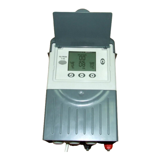
- Page 2 Features The “FILTRON 1-10” is a modular backflushing controller for automatic filters of 1 to 10 stations. Models come in both DC and AC variants. The DC model can be powered either by 6V DC or 12V DC and it activates 2 wired 12V DC latching solenoids.
-
Page 3: How To Program The Controller
How to Program the Controller The controller is equipped with an LCD display and 4 keys as displayed below. When the unit is left untouched for a minute the display is switched off and the only life signal is given by a beep sound that can be heard every 20 seconds. - Page 4 The screen consists of several fields, some of them are editable and some of them are not. For inserting EDIT MODE, push the ENTER key. The EDIT MODE is indicated by blinking of the characters at the currently editable field. Each time the ENTER key is pushed again, the next editable field becomes under focus and starts blinking.
- Page 5 Electronic DP connected. In this case the Digital DP input can be used. Up to version 1.02 of the Filtron 1-10, a nonzero value Set-point would have caused the controller to ignore the Digital DP input completely, but a zero Set-point would make the Digital DP effective and cause the Electronic DP to be ignored.
- Page 6 The Flush Mode The Flush Mode defines how the flushing cycles is triggered. The selectable options are as follows: OFF-By time - No flushing will take place. In this case, the flushing cycles will be repeated in a selected interval or will be triggered by the DP signal depending on which happens first.
- Page 7 The Configuration In order to enter into the configuration process press and hold down the ENTER key for at least 3 seconds. The unit will detect how many “plug-in” boards (each of 2 outputs) are used in the particular case. How the outputs will be allocated depends on the definitions made during the configuration process described below.
- Page 8 During the configuration process, the following features are defined: Main Valve (sustaining valve) - Yes/ No. When the answer is “Yes” the Pre Dwell delay can be set. The Pre Dwell delay is measured between the command to the Main Valve and the command to Station No.
- Page 9 Pressure Units - Deciding about the units to be used for pressure measurement. Selecting between BAR or PSI . Calibration - Zero calibration of the built in electronic DP sensor. While the sensor ports are disconnected select Calibration = Yes. Version display - The last screen of the configuration supplies information about the software version of the controller.
-
Page 10: Low Battery
Connecting the DP sensor to the filter system The DP sensor is connected to the filter system by 2 command tubes, the one which comes from the filter inlet (High pressure) will be connected to the red point, and the one that comes from the outlet (Lower pressure) will go to the black point. -
Page 11: Manual Activation
Manual Activation A flushing sequence can be manually activated by the “MANUAL” key. When manually activated the ‘palm’ icon will appear on the display. The same key will be used for manually terminating a sequence in progress. Timing Diagram Without Delay Valve National Service and Supply Centre 35 Wakefield Street, Alicetown 5010 www.deeco.co.nz... - Page 12 Including Delay Valve National Service and Supply Centre 35 Wakefield Street, Alicetown 5010 www.deeco.co.nz The information contained herein may be changed by Deeco Services without notice. Deeco Services shall not be held liable for any errors...
-
Page 13: Wiring Diagram
Wiring Diagram DC Model Note That : The external DP sensor is optional and it is intended for use in cases there is no embedded electronic DP included. The powering of the unit can be either by 6V DC or 12V DC. The solenoids will be of 12VDC Latch. - Page 14 AC Model Note That : The external DP sensor is optional and it is intended for use in cases there is no embedded electronic DP included. The powering of the unit is by 24VAC transformed from 220/110v AC. The solenoids will be 24V AC. National Service and Supply Centre 35 Wakefield Street, Alicetown 5010 www.deeco.co.nz...
-
Page 15: Technical Data
Technical Data DC Model Power Source : 6v supplied by 4 x 1.5 “D” size alkaline batteries or 12v DC dry battery or 12v rechargeable battery with solar panel of 2 watts Outputs: 12v DC latching solenoids. Embedded electronic analog DP sensor Pressure Sensor: Dry contact pressure sensor Operating Temperature:...
Need help?
Do you have a question about the Filtron 1-10 and is the answer not in the manual?
Questions and answers