Table of Contents
Advertisement
Available languages
Available languages
Quick Links
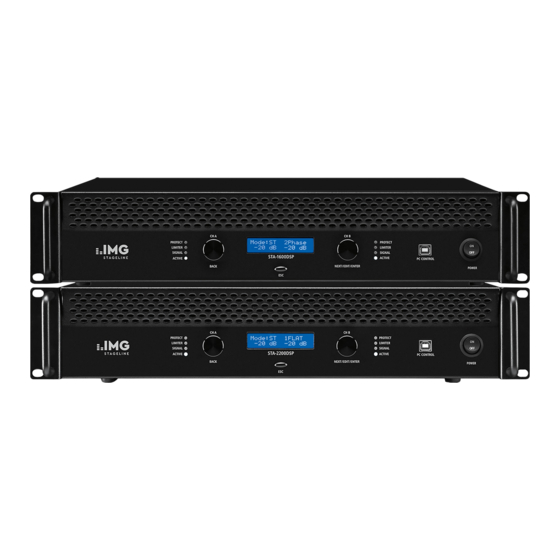
2-Kanal-PA-Verstärker mit DSP
2-Channel PA Amplifier with DSP
STA -1600 DSP
STA - 2200 DSP
BEDIENUNGSANLEITUNG
INSTRUCTION MANUAL
MODE D'EMPLOI
ISTRUZIONI PER L'USO
VEILIGHEIDSVOORSCHRIFTEN
CONSEJOS DE SEGURIDAD
ŚRODKI BEZPIECZEŃSTWA
SIKKERHEDSOPLYSNINGER
SÄKERHETSFÖRESKRIFTER
TURVALLISUUDESTA
ELECTRONICS FOR SPECIALISTS ELECTRONICS FOR SPECIALISTS ELECTRONICS FOR SPECIALISTS ELECTRONICS FOR SPECIALISTS
Bestellnummer • Order Number 25.9510
Bestellnummer • Order Number 25.9520
Advertisement
Table of Contents

Related Manuals for IMG STAGELINE STA-2200DSP


Summary of Contents for IMG STAGELINE STA-2200DSP
- Page 1 2-Kanal-PA-Verstärker mit DSP 2-Channel PA Amplifier with DSP STA -1600 DSP Bestellnummer • Order Number 25.9510 STA - 2200 DSP Bestellnummer • Order Number 25.9520 BEDIENUNGSANLEITUNG INSTRUCTION MANUAL MODE D’EMPLOI ISTRUZIONI PER L’USO VEILIGHEIDSVOORSCHRIFTEN CONSEJOS DE SEGURIDAD ŚRODKI BEZPIECZEŃSTWA SIKKERHEDSOPLYSNINGER SÄKERHETSFÖRESKRIFTER TURVALLISUUDESTA ELECTRONICS FOR SPECIALISTS ELECTRONICS FOR SPECIALISTS ELECTRONICS FOR SPECIALISTS ELECTRONICS FOR SPECIALISTS...
- Page 2 CH A CH B Mode:ST 1FLAT PROTECT PROTECT -20dB -20dB LIMITER LIMITER SIGNAL SIGNAL STA-2200DSP ACTIVE ACTIVE PC CONTROL BACK NEXT/EDIT/ENTER Abb. • Fig. 1 LINK CH A IN CH A PUSH BRIDGE CIRCUIT BREAKER CH B CH B IN...
- Page 3 Deutsch . . . . . . . . . . . Seite English . . . . . . . . . . . . Page Français .
- Page 4 2-Kanal-PA-Verstärker mit Signalprozessor Diese Anleitung richtet sich an Benutzer mit Grundkenntnissen in der Audiotechnik . Bitte lesen Sie die Anleitung vor dem Betrieb gründlich durch und heben Sie sie für ein späteres Nachlesen auf . Inhalt Übersicht . . . . . . . . . . . . . . . . . . . . . . . . . . .5 Fernsteuerung über einen Computer .
-
Page 5: Übersicht
Auf Seite 2 finden Sie alle beschriebenen Bedienelemente und Anschlüsse. 1 Übersicht 2 Hinweise für den sicheren Gebrauch Das Gerät entspricht allen relevanten Richt linien der EU und ist deshalb 1 Status-LEDs jeweils für die Kanäle A und B gekennzeichnet . PROTECT Schutzschaltung aktiv WARNUNG Das Gerät wird mit lebensgefährlicher Netzspannung LIMITER Übersteuerung des Verstärkers: Zum Verhindern von... -
Page 6: Aufstellmöglichkeiten
4 Aufstellmöglichkeiten 5.4 Stromversorgung Der Verstärker ist für den Einschub in ein Rack (483 mm /19”) vorge- Zur Stromversorgung das beiliegende Netzkabel erst mit der Netz- sehen, er kann aber auch auf einer ebenen Fläche aufgestellt werden . buchse (13) verbinden und dann an eine Steckdose (230 V/ 50 Hz) In jedem Fall muss Luft ungehindert durch alle Lüftungsöffnungen anschließen . -
Page 7: Signalweg
Alle Einstellungen des Verstärkers lassen sich als Konfiguration spei- Bridge Brückenbetrieb, bei dem beide Kanäle das Signal vom chern . Bis zu 30 Konfigurationen können im Verstärker gespeichert Eingang CH A IN bekommen und wieder aufgerufen werden . Die vor dem Ausschalten gespeicherte Die Kanäle haben identische Einstellungen, die über oder die zuletzt aufgerufene Konfiguration wird beim Wiedereinschal- Kanal A vorgenommen werden . -
Page 8: Gespeicherte Konfiguration Aufrufen
punkte beschrieben . Eine ausführlichere Beschreibung der Einstell- 6.3.7 Dynamikkompressor möglichkeiten erfolgt in Kapitel 7 . 7 Compressor Wird länger als eine Minute keine Bedienung vorgenommen, Kompressor aus /ein (gekoppelt mit „Limiter“) schaltet der Verstärker wieder auf die Hauptanzeige (Abb . 5) zurück . Schwellwert (threshold) in dBV: Nach dem Drücken des Knopfes NEXT/ EDIT / ENTER kann dann die …... -
Page 9: Fernsteuerung Über Einen Computer
7 Fernsteuerung über einen Computer 7.1 Installation der PC-Software Diese Anleitung bezieht sich auf die Version 2 .26 der PC-Software . Systemvoraussetzung für die Installation des mitgelieferten Steuer- programms ist ein Computer mit dem Betriebssystem Windows XP mit Service Pack 3 oder einer höheren Windows-Version . Die Bildschirm auflösung sollte mindestens 1024 ×... -
Page 10: Datensicherung Über Den Computer
7.3.4 Datensicherung über den Computer Das aktuelle Kennwort eingeben und durch Klicken auf „Accept“ bestätigen . Bei falsch eingegebenem Kennwort erscheint die Meldung Alle Einstellungen des Verstärkers können, zur Datensicherung oder „Wrong!“ . In diesem Fall die Meldung bestätigen und das Kennwort um sie auf einen anderen Verstärker zu übertragen, auf dem Com- erneut eingeben . -
Page 11: Ansicht „Work Mode
Über die Schaltfläche BYPASS das Filter ein- oder ausschalten . ☞ Abb . 10) . Bei falsch eingegebenem Kennwort erscheint die Mel- dung „Wrong!“ . In diesem Fall die Meldung bestätigen und das Kenn- 7.4.2.2 Grafische Filtereinstellung wort erneut eingeben . Die Filterparameter können zum Teil auch grafisch eingestellt werden . -
Page 12: Ansicht „Delay
7.4.3 Ansicht „Delay“ 7.4.5 Ansicht „Compressor, Limiter“ In dieser Ansicht kann eine Verzögerung der Signale (z . B . zur Kom- In dieser Ansicht können Einstellungen zur Kompression und Pegel- pensation unterschiedlicher Lautsprecherabstände) eingestellt werden begrenzung vorgenommen werden . Der Kompressor reduziert die (vgl . -
Page 13: Einstellung Des Limiters
: Nennleistung (Sinusleistung) bei entsprechender Impedanz 10 Technische Daten gewünschte maximale Leistung bei gleicher Impedanz Modell STA-1600DSP STA-2200DSP Beispiel: Ausgangsleistung Ein 8-Ω-Lautsprecher soll am Ausgang CH A OUT des STA-1600DSP Sinusleistung auf eine Belastung von 50 W begrenzt werden . - Page 14 2-Channel PA Amplifier with DSP These instructions are intended for users with basic knowledge in audio technology . Please read the instructions carefully prior to operation and keep them for later reference . Contents Safety Notes . . . . . . . . . . . . . . . . . . . . . . . . 15 Remote Control via a Computer .
- Page 15 All operating elements and connections described can be found on page 2. 1 Overview 2 Safety Notes The unit corresponds to all relevant directives of the EU and is therefore 1 Status LED indicators, one each for channels A and B marked with PROTECT protective circuit active WARNING The unit uses dangerous mains voltage .
- Page 16 4 Setup Options 5.4 Power supply For power supply, connect the mains cable provided to the mains The amplifier is designed for installation into a rack (483 mm/19”), but jack (13) and then to a mains socket (230 V/ 50 Hz): Connect the blue can also be placed on a flat surface .
- Page 17 All settings of the amplifiers can be saved as configurations . A maxi- Bridge Bridge mode; both channels receive the signal from input mum of 30 configurations can be saved in the amplifier and called up . CH A IN When the amplifier is switched on, the configuration saved before the The channels have identical settings;...
- Page 18 When no operation is made, the amplifier will automatically 6.3.7 Dynamic range compressor return to the main display (fig . 5) after one minute . Press the knob 7 Compressor NEXT/ EDIT / ENTER to continue making settings in the submenu you to deactivate /activate the compressor (linked with previously called up .
- Page 19 7 Remote Control via a Computer 7.1 Installing the PC software These instructions refer to version 2 .26 of the PC software . To install the control program supplied, a computer with the operating system Windows XP with Service Pack 3 or a higher Windows version is required .
- Page 20 7.3.4 Data backup via the computer Enter the current password and then click “Accept” to confirm . When an invalid password is entered, the message “Wrong!” will appear: It is possible to save all settings of the amplifier on the computer, either Confirm the message and re-enter the password .
- Page 21 “Wrong!” will appear: Confirm the message and re-enter the pass- 7.4.2.2 Graphical filter setting word . Some of the filter parameters can also be changed graphically . For this purpose, keep the left mouse button pressed and move the ap- 7.4.1 View “Work Mode”...
- Page 22 7.4.3 View “Delay” 7.4.5 View “Compressor, Limiter” In this view, the signal delay (e . g . to compensate different distances In this view, compression and level limitation settings can be made . The between speakers and audience) can be set (cf . chapter 6 .3 .5): compressor reduces the dynamic range and attenuates the level above an adjustable threshold .
- Page 23 : rated power (RMS power) for the corresponding imped- 10 Specifications ance Model STA-1600DSP STA-2200DSP desired maximum power for the same impedance Output power Example: RMS power At the output CH A OUT of the STA-1600DSP, an 8 Ω speaker is to be Stereo at 4 Ω...
- Page 24 Amplificateur 2 canaux avec processeur de signal Cette notice d’adresse aux utilisateurs avec des connaissances techniques en sonorisation . Veuillez lire la présente notice avant le fonctionnement et conservez-la pour pouvoir vous y reporter ultérieurement . Table des matières Présentation . . . . . . . . . . . . . . . . . . . . . . . . 25 Commande à...
- Page 25 Vous trouverez sur la page 2 la description des éléments et branchements. 1 Présentation 2 Conseils d’utilisation et de sécurité L’appareil répond à toutes les directives nécessaires de l’Union euro- 1 LEDs d’état, respectivement pour le canal A et le canal B péenne et porte donc le symbole PROTECT circuit de protection activé...
- Page 26 4 Positionnement de l’amplificateur 5.4 Alimentation Reliez tout d’abord le cordon secteur livré à la prise (13) puis à une L’amplificateur est conçu pour une installation dans un rack avec une prise secteur 230 V/ 50 Hz . Insérez la fiche Powercon bleue du cordon largeur de 483 mm (19”), il peut également être posé...
- Page 27 tions dans l’amplificateur et de les rappeler . A l’allumage, la dernière Bridgé Mode avec lequel les deux canaux reçoivent le signal de configuration mémorisée avant l’arrêt ou la configuration appelée le l’entrée CH A IN plus souvent est automatiquement chargée . Les modifications non Les canaux ont des réglages identiques qui sont effectués mémorisées sont perdues à...
- Page 28 Si aucune utilisation n’est faite pendant plus d’une minute, l’ampli- 6.3.7 Compresseur dynamique ficateur revient à l’affichage principal (schéma 5) . Après avoir appuyé 7 Compressor sur le bouton NEXT/ EDIT / ENTER, le réglage peut se poursuivre au compresseur activé / désactivé (couplé avec «Limiter») sous-menu précédemment appelé...
- Page 29 7 Commande à distance via un ordinateur 7.1 Installation du software PC Cette notice se réfère à la version 2 .26 du Software PC . Configuration requise pour l’installation du programme de gestion livré : ordina- teur avec système d’exploitation Windows XP avec Service Pack 3 ou une version Windows supérieure .
- Page 30 7.3.4 Sauvegarder les données via un ordinateur Saisissez le mot de passe actuel et confirmez en cliquant sur «Accept» . Si un mot de passe erroné est saisi, le message «Wrong!» s’affiche . Tous les réglages d’un amplificateur peuvent être mémorisés sur l’or- Dans ce cas, confirmez le message et saisissez à...
- Page 31 Si le mot de passe actuel n’a pas encore été saisi depuis le dé- – filtre Linkwitz-Riley ; pente : 12 ou 24 dB / octave marrage du programme, le message demandant de le saisir s’af- Via le bouton BYPASS activez ou désactivez le filtre . ☞...
- Page 32 7.4.3 Fenêtre «Delay» 7.4.5 Fenêtre «Compressor, Limiter» Cette fenêtre permet d’effectuer les réglages pour la compression et Dans cette fenêtre, vous pouvez régler une temporisation des signaux la limitation de niveau . Le compresseur réduit la dynamique et atténue (par exemple pour compenser des distance différentes entre les en- le niveau au-dessus d’un seuil réglable .
- Page 33 10 Caractéristiques techniques √ P Valeur seuil limiteur = 20 log : puissance nominale (puissance RMS) pour impédance Modèle STA-1600DSP STA-2200DSP correspondante Puissance de sortie Puissance RMS puissance maximale souhaitée pour impédance identique Stéréo sous 4 Ω 2 × 800 W 2 ×...
- Page 34 Amplificatore PA a 2 canali con processore di segnale Queste istruzioni sono destinate agli utenti con conoscenze di base in tecnologia audio . Si prega di leggere attentamente le istruzioni prima dell’uso e conservarle per riferimenti futuri . Contenuto Panoramica . . . . . . . . . . . . . . . . . . . . . . . . . 35 Controllo remoto tramite computer .
- Page 35 Tutti gli elementi operativi e i collegamenti descritti sono ri- portati a pagina 2. 1 Panoramica 2 Note di sicurezza L’unità corrisponde a tutte le direttive pertinenti dell’UE e pertanto è 1 Indicatori LED di stato, uno ciascuno per i canali A e B contrassegnata con PROTECT il circuito di protezione attivo AVVERTIMENTO L’unità...
- Page 36 4 Opzioni di installazione 5.4 Alimentazione elettrica Per l’alimentazione, collegare il cavo di alimentazione in dotazione L’amplificatore è progettato per l’installazione in un rack (483 mm / 19”), alla presa di rete (13) e quindi a una presa di corrente (230 V/ 50 Hz): ma può...
- Page 37 vate nell’amplificatore e richiamate . All’accensione dell’amplificatore, Bridge Modalità bridge; entrambi i canali ricevono il segnale la configurazione salvata prima della disattivazione dell’amplificatore dall’ingresso CH A IN o la configurazione richiamata più di recente viene caricata automa- I canali hanno impostazioni identiche; le impostazioni ticamente .
- Page 38 vono brevemente le dieci voci principali del menu . Per una descrizione 6.3.7 Compressore gamma dinamica dettagliata delle impostazioni, fare riferimento al capitolo 7 . 7 Compressor Quando non viene eseguita alcuna operazione, l’amplificatore per disattivare / attivare il compressore (collegato con ritornerà...
- Page 39 7 Controllo remoto tramite computer 7.1 Installazione del software per PC Queste istruzioni si riferiscono alla versione 2 .26 del software per PC . Per installare il programma di controllo fornito, è necessario un computer con il sistema operativo Windows XP con Service Pack 3 o una versione di Windows superiore .
- Page 40 7.3.4 Backup dei dati tramite il computer Immettere la password corrente e quindi fare clic su “Accept” per confermare . Quando viene immessa una password non valida, viene È possibile salvare tutte le impostazioni dell’amplificatore sul com- visualizzato il messaggio “Wrong!”: Confermare il messaggio e rein- puter, sia per il backup dei dati che per il trasferimento su un altro serire la password .
- Page 41 Utilizzare il pulsante BYPASS per attivare o disattivare il filtro . ☞ fig . 10) . Quando viene immessa una password non valida, viene visualizzato il messaggio “Wrong!”: Confermare il messaggio e rein- 7.4.2.2 Impostazione grafica del filtro serire la password . Alcuni dei parametri del filtro possono anche essere modificati grafi- camente .
- Page 42 7.4.3 Vista “Delay” 7.4.5 Vista “Compressor, Limiter” In questa vista, è possibile effettuare le impostazioni di compressione In questa vista, è possibile impostare il ritardo del segnale (ad esempio e limitazione del livello . Il compressore riduce la gamma dinamica e per compensare le diverse distanze tra i diffusori e il pubblico) (vedi attenua il livello al di sopra di una soglia regolabile .
- Page 43 : potenza nominale (potenza RMS) per l’impedenza corri- 10 Specifiche spondente potenza massima desiderata per la stessa impedenza Modello STA-1600DSP STA-2200DSP Esempio: Potenza di uscita All’uscita CH A OUT di STA-1600DSP, un altoparlante da 8 Ω deve Potenza RMS Stereo a 4 Ω...
-
Page 44: Italiano
• De warmte die in het apparaat ontstaat, worden gesteld voor gegevensverliezen als Lees aandachtig de onderstaande veiligheids- moet door ventilatie afgevoerd worden . gevolg van foutieve bediening of een de- voorschriften, alvorens de apparaten in ge- Dek daarom de ventilatieopeningen niet af . fect, noch voor de schade die hieruit volgt . - Page 45 Przed obsługą urządzenia należy wcześniej • Ciepło wytwarzane podczas pracy urządze- z ich przeznaczeniem, nieprawidłowo za- zapoznać się z następującymi uwagami od- nia musi być odprowadzane przez otwory montowane, podłączone lub obsługiwane nośnie środków bezpieczeństwa . Więcej wentylacyjne . W związku z tym nie wolno bądź...
-
Page 46: Suomi
Ge akt på säkerhetsinformationen innan en- heten tas i bruk . Skulle ytterliggare informa- tion behövas kan den återfinnas i Manualen för andra språk . Säkerhetsföreskrifter Denna enhet uppfyller alla relevanta direktiv • Ta omedelbart kontakten ur eluttaget om ansvar för uppkommen skada på person inom EU och har därför fått märkning . - Page 48 MONACOR INTERNATIONAL GmbH & Co. KG • Zum Falsch 36 • 28307 Bremen • Germany A-1917 .99 .02 .05 .2019 Copyright by MONACOR INTERNATIONAL. All rights reserved. ©...
Need help?
Do you have a question about the STA-2200DSP and is the answer not in the manual?
Questions and answers