Table of Contents
Advertisement
VIESMANN
Installation and service instructions
for contractors
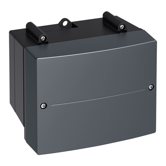
Mixer extension kit
ADIO electronics module
Mixer extension kit EM-M1 for one heating circuit with mixer, wall mounting
Mixer extension kit EM-MX for one heating circuit with mixer, mixer mounting
Mixer extension kit EM-MX for one heating circuit with mixer, mixer mounting,
Divicon heating circuit distributor
Mixer extension kit
Please keep safe.
5838001 GB
12/2018
Advertisement
Table of Contents

Related Manuals for Viessmann EM-M1


Summary of Contents for Viessmann EM-M1
- Page 1 Mixer extension kit ADIO electronics module Mixer extension kit EM-M1 for one heating circuit with mixer, wall mounting Mixer extension kit EM-MX for one heating circuit with mixer, mixer mounting Mixer extension kit EM-MX for one heating circuit with mixer, mixer mounting,...
- Page 2 Never touch hot surfaces on the boiler, burner, lidate our warranty. ■ flue system or pipework. For replacements, use only original spare parts supplied or approved by Viessmann. Please note Electronic assemblies can be damaged by elec- trostatic discharge. Prior to commencing work, touch earthed objects such as heating or water pipes to dis- charge static loads.
- Page 3 Safety instructions Safety instructions (cont.) Safety instructions for operating the system If you smell gas Flue systems and combustion air Danger Ensure that flue systems are clear and cannot be Escaping gas can lead to explosions which may sealed, for instance due to accumulation of conden- result in serious injury.
-
Page 4: Table Of Contents
Index Index Information Disposal of packaging ................Symbols ....................System examples .................. Installation sequence Mounting the mixer extension kit ............Mixer mounting ................... ■ Wall mounting ..................■ Mounting the temperature sensor ............Installing the flow temperature sensor (contact temperature sensor) . ■... -
Page 5: Disposal Of Packaging
In conjunction with a tool: Clean the sur- ■ face. Dispose of component correctly. Dispose of component at a suitable collec- tion point. Do not dispose of component in domestic waste. System examples For available system examples, see www.viessmann- schemes.com... -
Page 6: Mounting The Mixer Extension Kit
Installation sequence Mounting the mixer extension kit Mixer mounting M6/M8 Fig. 1 Wall mounting Fig. 2... -
Page 7: Mounting The Temperature Sensor
Installation sequence Mounting the temperature sensor Installing the flow temperature sensor (contact temperature sensor) Fit the flow temperature sensor to the heating flow Clean the contact area on the pipe down to bare ■ ■ pipe immediately downstream of the heating circuit metal. -
Page 8: Overview Of Electrical Connections
Installation sequence Overview of electrical connections [{] [{] [{] [{{] fÖ sÖ L ? N L ? N 230 V~/50 Hz Fig. 4 Plug 230 V~ Please note sÖ Heating circuit pump (on site) Electronic assemblies can be damaged by elec- Mixer motor trostatic discharge. -
Page 9: Mixer Motor
Installation sequence Connecting the mixer motor (cont.) Mixer motor Connect the mixer motor in accordance with the dia- gram in the wall mounting base of the extension kit. Never interchange wires. Fig. 5 Plug on mixer motor Plug on mixer extension kit Mixer open Mixer close Mixer motors without plug or on-site mixer motors... -
Page 10: Connecting The Heating Circuit Pump
Installation sequence Connecting the heating circuit pump Note In underfloor heating circuits, install a temperature lim- iter on site to restrict the maximum temperature of the underfloor heating system. Heating circuit pump 230 V~ Specification Rated current Recommended connecting H05VV-F3G 0.75 mm cable H05RN-F3G 0.75 mm Fig. -
Page 11: Heating Circuit Pump 400 V
Installation sequence Connecting the heating circuit pump (cont.) Pumps without switching input Specification for switching the contactor: Rated voltage 230 V∼ Rated current Recommended connecting H05VV-F3G 0.75 mm cable H05RN-F3G 0.75 mm N PE Fig. 9 Heating circuit pump Plug on the mixer extension kit sÖ... -
Page 12: Temperature Limiter For Maximum Temperature Limiter (Accessories)
Installation sequence Connecting the heating circuit pump (cont.) Pumps in the underfloor heating circuit (in case of system separation) The common power consumption of both pumps must sÖ not exceed 1 A. Fig. 11 Plug on mixer extension kit sÖ Primary heating circuit pump Temperature limiter Secondary heating circuit pump... -
Page 13: Rotary Switch S1 For Subscriber Number Addressing
Installation sequence Rotary switch S1 for subscriber number addressing Note The rotary switch can be found on the PCB of the elec- tronics module. Set rotary switch S1. System with one heating circuit with mixer: Heating circuit 2 with mixer: Rotary switch on exten- ■... -
Page 14: Power Supply
Installation sequence Power supply Power supply at heat generator Create the power supply connection. Route the power cable to the heat generator and con- nect to plug . Observe MCB/fuse protection, out- put, plug of the heat generator. If power is supplied to a further accessory, use plug A provided fÖ... - Page 15 Installation sequence Power supply (cont.) Connect the power supply in accordance with the dia- gram. If the power supply to the appliance is connected with a flexible cable, ensure that the live conductors are pulled taut before the earth conductor in the event of strain relief failure.
-
Page 16: Connecting Several Accessories
Installation sequence Connecting several accessories Power supply and PlusBus connection Power supply to all accessories via heat generator control unit Fig. 17 Some accessories with direct power supply Fig. 18 Heat generator control unit ON/OFF switch Mixer extension kit for heating circuit with fÖ... -
Page 17: Rotational Direction Of The Mixer Motor
Installation sequence Commissioning (cont.) Rotational direction of the mixer motor Checking the rotational direction of the mixer motor After being switched on, the appliance implements a Observe the rotational direction of the mixer motor dur- self-test. During this, the mixer is opened and closed ing its self-test. -
Page 18: Parts List
Parts lists Parts list The following details are required when ordering parts: ■ Serial no. (see type plate) ■ Position number of the part... -
Page 19: Wall Mounting
Parts lists Parts list (cont.) Wall mounting 0001 0015 0014 0006 0013 0005 0002 0004 Fig. 20... - Page 20 Parts lists Parts list (cont.) Pos. Part 0001 ADIO electronics module 0002 Flow temperature sensor NTC 0004 Connecting cable fÖ 0005 PlusBus cable 0006 Plug set 0013 Strain relief 0014 Fuse 2.0 A (slow), 250 V~ (10 pce) 0015 Installation and service instructions...
-
Page 21: Mixer Mounting
Parts lists Parts list (cont.) Mixer mounting 0013 0012 0011 0009 0015 0010 0014 0006 0001 0002 0004 0005 0008 Fig. 21... - Page 22 Parts lists Parts list (cont.) Pos. Part 0001 Extension 0002 Flow temperature sensor NTC 0004 Connecting cable fÖ 0005 PlusBus cable 0006 Plug set 0008 Mixer connecting cable 0009 Motor module 0010 Motor lever 0011 Base plate 0012 Fixing kit 0013 Strain relief 0014...
-
Page 23: Specification
Specification Specification Rated voltage 230 V∼ Rated frequency 50 Hz Rated current Power consumption – electronics Wall mounting 1.5 W ■ Mixer mounting 5.5 W ■ Power consumption Wall mounting 7 mA ■ Mixer mounting 25 mA ■ IP rating IP 20D to EN 60529, ensure through design/ installation Permissible ambient temperature... -
Page 24: Connection And Wiring Diagram
Specification Connection and wiring diagram Fig. 23 A1 Mixer extension kit PCB S1 Rotary switch for subscriber number addressing A2 PCB Mixer motor if wall mounted F1 Fuse Mixer motor if mixer mounted 230 V~ plugs No function Heating circuit pump (on site) Temperature sensor, low loss header sÖ... -
Page 25: Declaration Of Conformity
Declaration of Conformity Declaration of conformity Declaration of Conformity We, Viessmann Werke GmbH & Co. KG, D-35107 Allendorf, declare as sole responsible body that the named product complies with the European directives and supplementary national requirements in terms of its design and operational characteristics. - Page 26 Keyword index Keyword index Connection and wiring diagram........24 Pumps – Underfloor heating circuit........12 Electrical connections..........8 Extension kit mounting..........6 Specification...............23 System examples............5 Flow temperature sensor – Connecting..............8 Temperature limiter............ 12 – Mounting..............7 Temperature sensor for low loss header –...
- Page 28 Viessmann Werke GmbH & Co. KG Viessmann Limited D-35107 Allendorf Hortonwood 30, Telford Telephone: +49 6452 70-0 Shropshire, TF1 7YP, GB Fax: +49 6452 70-2780 Telephone: +44 1952 675000 www.viessmann.com Fax: +44 1952 675040 E-mail: info-uk@viessmann.com...
Need help?
Do you have a question about the EM-M1 and is the answer not in the manual?
Questions and answers