Advertisement
Quick Links
Advertisement

Related Manuals for Digital Guard Dawg 2GO KEYLESS iKEY RS

Summary of Contents for Digital Guard Dawg 2GO KEYLESS iKEY RS
- Page 2 Package Contents ………..........4 Pre-Installation Information and Preparation ....5 Major Component information…........6 Part #1 Passive Keyless Door Lock & Alarm…....8 D o o r L o c k & A l a r m M o d u l e ( H a r n e s s C o n n e c t i o n s ) ..9 D o o r L o c k i n g S y s t e m W i r i n g .
- Page 3 1) This product must be installed by a qualified professional according to these instructions and observing all safety features. 2) The Digital Guard Dawg Inc. accepts no responsibility for any electrical damage resulting from improper installation of the product, be that either damage to the vehicle itself or to the product.
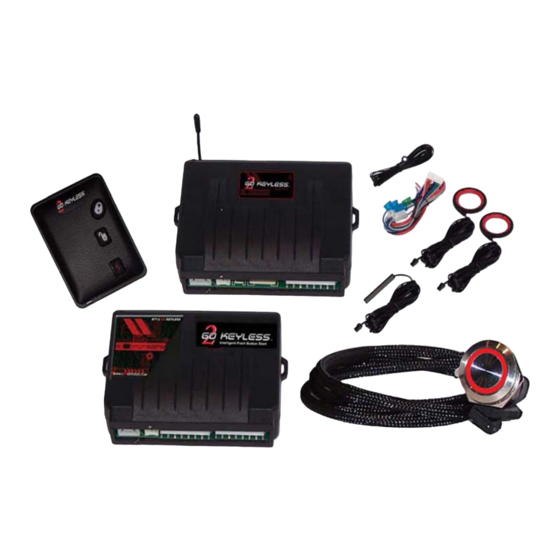
- Page 4 KEYLESS™ PKE- & PBS systems come in individual boxes. The following is a list of components included with each kit: PKE Door Lock & Alarm Kit: 1 – Door Lock & Alarm Control Unit 1 – RFID iKey™ 1 – RFID Emergency Card 1 –...
- Page 5 Overview: Completely read this manual and review the wiring diagram carefully. It is recommended that you complete your installation in two parts. Part 1~Installation of the Door Lock and Alarm module & Harnesses. Part 2~Installation of the Push Button–Remote Start & Harnesses. Always install in a well-lit, dry, covered area away from the elements and keep at least one window open during installation to avoid a lock out.
- Page 6 Route the wires of the harnesses along factory wiring to areas in which the different connections will be made. DO NOT plug the two wiring harnesses into the Control Module until all connections have been completed. When running the harness wires through the vehicle, be careful to run them where they could be damaged or shorted to GROUND.
- Page 7 Control Module and Push Button Start Module: Select a mounting location behind the dash, and secure using cable ties. Be certain that the chosen location will not interfere with the proper operation of the vehicle. Avoid mounting the module to or routing the wiring around the steering column, as the module or wiring could wrap around or block the steering wheel preventing proper control of the vehicle.
- Page 8 The Door Lock and Alarm Module will provide completely automatic operation of all vehicle doors and all security functions. PKE Module iKey™ As you approach your vehicle doors will unlock upon seeing a valid iKey™ Walk away from the vehicle, all doors auto lock and security features arm Installation should begin with selecting a location to mount the system module and locating of all signal wires listed below.
- Page 9 Connect the Ground wire first before making the 12-volt connections to the Module. Powering up before grounding could damage the system! PKE Door Lock & Alarm ~ Main Harness (7-Pin) Use wire color for identification, Actual wire order in harness m ay be different. Wire Description Connect to the 12V supply wire of the Ignition harness.
- Page 10 Door Lock & Alarm ~ Accessory Harness (7-Pin) Wire Description This wire is for sensing when the vehicle is ON. It should be connected to an Ignition wire that has +12 V when the Ignition Key or Push Button Start is in the and ON (RUN) position. Vehicle ON Detect Special instructions when using Remote Starter: Connect to different ACC wire if the vehicle has 2nd ACC.
- Page 11 All power door locking systems utilize switches or a central computer called the Body Control Module (BCM) to control the locking and unlocking of the vehicle. The switch is usually located on the door or center console while the BCM is usually located under the Dash.
- Page 12 Aftermarket Data Interfaces If an aftermarket Data Interface is being used, please refer to its manual. The interface may be able to LOCK and UNLOCK the door using the data wires of the vehicle. The Vehicle’s Receiving (RX) and Transmission (TX) wires can be referred to in the Data Interface’s manual.
- Page 13 Negative or Positive Door Trigger The Green wire in the 7 PIN Accessory harness is used to sense when a vehicle door is open. It will need to be connected to your vehicle’s dome light circuit or individual door triggers. Generally, most vehicles have an overall signal wire which will trigger a signal no matter which door is opened.
- Page 14 Once the proper connection type is determined verify the type of door trigger for your vehicle. After locating the proper wire, shut off the interior lights first, then open the driver side’s door, keeping the other doors closed; Then check the voltage, if the voltage is ground with the door open and becomes positive voltage when the door is closed, then it is a negative trigger type.
- Page 15 The Front (Main) antenna is your primary system antenna. It is not necessary to use both main antennas If antiquate range is achieved with only the Front main antenna. The “Y” antenna connector harness provided MUST be use even when only one antenna is installed.
- Page 16 Door Lock & Alarm Module Function “Jumper Set” On the side of the control module there is a set of Four Jumpers that are used to select specific module functions. JP1: Door Trigger (-) ←→ Door Trigger (+): The default setting is Negative Door Trigger. If the user’s vehicle is Positive Door Trigger switch the JP1 to Door Trigger (+).
- Page 17 The 2GO Keyless™ PBS Module Push Button –Remote Start) contains all the system relays to operate Ignition and accessory circuits. The PBS Module eliminates the “spaghetti look” of hand wiring multiple external relays. Independent switching of two Ignition circuits and one accessory circuit allows The PBS Module to be configured in several different ways: One Ignition circuit can be turned OFF during starter “crank”...
- Page 18 Newer Vehicles with Factory Immobilizers or Multiplex Wiring. 2GO Keyless™ can be installed on virtually any new vehicle and add the Convenience & Security of keyless operation. 2GO Keyless™ will integrate with even the most sophisticated vehicle electrical systems and will provide completely keyless operation similar to systems found on the today’s most prestigious vehicles.
- Page 19 Another popular option for Mechanical steering locks is to simply “Release” the lock. If you are not concerned about the lock actually being “removed”, but could be happy simply having it “released” and hidden, there is another very popular option that will work well for a large number of vehicles. With this method rather then removing the existing steering column lock;...
- Page 20 Once you have decided which type of installation is right for your vehicle. Locate the vehicle Main Ignition switch harness. Begin by locating all Ignition and signal wires listed below and then connect wires according the wire diagram. Make sure to connect the Ground wire first before making the 12-volt connections or powering up the PBS Module Push Button Start ~ Main Harness (8-Pin)
- Page 21 Push Button Start ~ Accessory Harness (10-Pin) Wire Description Orange This wire provides a constant 250mA positive output 1 second before the vehicle is started to activate a Data Data Module or Bypass module Trigger This wire is a +12v constant supply wire used to supply power to External High Current Relays (optional) +12V Supply...
-
Page 22: Neutral Safety Switch Interface
This wire senses when you step on the Brake. It Brown allows the system to enter “Start” mode. The wire will (+) Brake or be +12V as you depress the brake pedal, and will be Clutch ground when release brake. Optional: Blue External High Current Relay Control for Ignition #2... - Page 23 Additional Safety Recommendations: A toggle switch is suggested to be installed as shown in Figure B, therefore the remote start function can be disable when necessary. For example, the vehicle is in the servicing, or parks in an enclosed or partially enclosed area without ventilation.
- Page 24 Pre Testing: It is always also always a good idea to do the following test to confirm basic system function and make sure everything up to this point is connected correctly: Shut all vehicle doors and remove all the systems iKey(s) to a distance of at least 25’...
- Page 25 Tachometer Programming After making all your connections to both the PKE & PBS modules, the final step is to program the system to learn your vehicles tachometer signal. This is necessary so that the systems Remote Start & One Touch Starting functions can determine when you vehicles engine is running.
- Page 26 APPENDIX “A”...
- Page 27 APPENDIX “B” Figure 1 Figure 2 Figure 3...
- Page 28 FOR UNIT TO FUNCTION CORRECTLY YOU MUST CONNECT: (Brown) Brake Pedal Wire and (Green) Door trigger wires.
- Page 29 The PBS module is designed with four 40Amp internal relays. One for each of the primary system circuits: IGN 1 / IGN 2 / ACC / START...
- Page 30 For High Current Ignition applications requiring greater than 40 Amps for each ignition circuits. you must use the additional pre-wired pair of external 40AMP relays included with your PBS Accessory harness. This will greatly increase your ignitions current handling. These should be used on Heavy duty vehicles, dual AC systems, extensive Lighting, Audio or other accessories with higher then normal current requirements.
- Page 31 As you approach your vehicle upon seeing a valid iKey™: ~Vehicle doors will unlock ~Parking lights will flash Twice ~If connected the Siren / Horn will “Chirp” Twice ~The LED in the Start Button will light When you enter the vehicle: If you do not step on the Brake Pedal the system will work as follows: ~Push the button once and turn on the ACCESSORIES ~Push the button once more and on IGNITION 1 &...
-
Page 32: Replacing The Battery
The iKey ™ Replacing the battery: Use CR2032 lithium disk battery available at most drug stores. Make sure the battery is inserted with the correct polarity. Be extremely careful not to bend the battery contacts when inserting the new battery. Before inserting the new battery, slightly push the battery contacts towards each other to ensure that that good contact is made with the new battery. -
Page 33: Additional System Features
Additional System Features Alarm: If the system could not find a valid iKey™ in range, and the door was opened, or someone tried to start the engine via the ignition cylinder, the system will trigger an alarm: the horn / siren will sound and the turn indicator lights will flash. The horn sounding and light flashing will stop after period of 90 sec when no further vehicle status changes are detected, however the starter will remain disabled. -
Page 34: Very Important
ACC position if you need to wait or rest in the vehicle for extended periods of time VERY IMPORTANT KEY CODE: The number on the packaging of your iKey™ is your systems “Key Code” Write it down and store it in a safe place. You will need this number if you would like to order additional iKeys™...
Need help?
Do you have a question about the 2GO KEYLESS iKEY RS and is the answer not in the manual?
Questions and answers