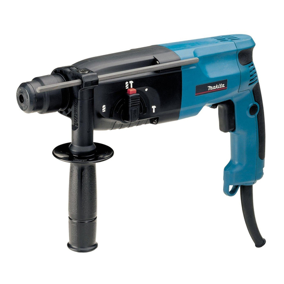
Makita HR2450FT Technical Information
24mm (15/16") rotary hammer
Hide thumbs
Also See for HR2450FT:
- Instruction manual (57 pages) ,
- Instruction manual (57 pages) ,
- Instruction manual (19 pages)
Advertisement
Quick Links
Download this manual
See also:
Instruction Manual
T
ECHNICAL INFORMATION
Models No.
Description
C
ONCEPTION AND MAIN APPLICATIONS
The above models are the advanced version of MAKITA's
famous 3 -mode rotary hammer HR2450.
Each new model features :
HR2450T : possible to quickly change from
the chuck for SDS-plus to keyless
drill chuck mutually without any tool
HR2450FT : equipped with built in job light
in addition to HR2450T's feature
S
pecification
Voltage (V)
110
120
220
230
240
Model No.
No load speed : (min
Blows per min, :(bpm=min
Single blow energy ( J )
Variable switch
Reverse switch
Bit shank
Concrete : mm (")
Steel. : mm (")
Wood : mm (")
Protection against electric shock
Built in job light
Cord length : m ( ft )
Net weight :Kg (lbs )
S
tandard equipment
* Stopper pole ........................ 1 pc.
* Quick change drill chuck ..... 1 pc.
* Plastic carrying case ............ 1 pc.
< Note > The standard equipment for the tool shown may differ from country to country.
O
ptional accessories
* T.C.T hammer drill bits 5.5mm - 24mm
* Bull point 14mm (9/16")
* Cold chisel 20mm (13/16")
* Scaling chisels 38mm and 50mm
* Grooving chisels 8mm and 12mm
* Scraper assembly
HR2450FT, HR2450T
24mm (15/16") Rotary Hammer
Cycle (Hz)
Current (A)
7.5
50 / 60
6.7
50 / 60
3.7
50 / 60
3.6
50 / 60
3.4
50 / 60
HR2450FT
= rpm)
0 - 1,100
-1
0 - 4,500
-1)
2.7
Yes
Yes
SDS plus type
* 24 (15/16 )
13 (1/2 )
32 (1-1/4 )
double insulation
Yes
** 4 (13.1)
2.6 (5.7)
* Side grip ..................... 1 pc.
(7/32" - 15/16")
(1-1/2" and 2")
(5/16" and 1/2")
Dimensions : mm ( " )
Model No.
HR2450FT
Length ( L )
Height ( H )
212 (8-3/8)
Width ( W )
Continuous Rating (W)
Input
780
780
780
780
780
HR2450T
0 - 1,100
0 - 4,500
2.7
Yes
Yes
SDS plus type
* 24 (15/16 )
13 (1/2 )
32 (1-1/4 )
double insulation
No
** 4 (13.1)
2.6 (5.7)
* Core bits
* Center bits
* Core bit adaptor
* Rod
* Core bits (dry type)
* Taper shank adaptor
* Taper shank T.C.T.hammer drill bits
* SDS plus hammer chuck set
* SDS plus adapter
L
W
HR2450T
384 (15-1/8)
204 (8)
72 (2-13/16)
Max. Output(W)
Output
370
370
370
370
370
* 25mm (1") for USA.
** 2.5m (8.2 ft) for Asia
** 2.0m (6.6 ft) for Australia
* Dust cups 5 and 9
* Safety goggle
* Bit grease
* Blow out bulb
* Dust extractor attachment
* Hammer service kit
PRODUCT
P 1 / 22
H
650
650
650
650
650
Advertisement

Related Manuals for Makita HR2450FT


Summary of Contents for Makita HR2450FT
- Page 1 HR2450FT, HR2450T Description 24mm (15/16") Rotary Hammer ONCEPTION AND MAIN APPLICATIONS The above models are the advanced version of MAKITA's famous 3 -mode rotary hammer HR2450. Each new model features : HR2450T : possible to quickly change from the chuck for SDS-plus to keyless Dimensions : mm ( "...
- Page 2 < 1 > Lubrication to the bit holder section Apply MAKITA grease to the following portions to protect parts and product from unusual abrasion. * MAKITA grease RA No.1 to the portions designated with black triangle. * MAKITA grease FA No. 2 to the portions designated with gray triangle.
- Page 3 < 2 > Lubrication to the machine parts Apply MAKITA grease to the following portions to protect parts and product from unusual abrasion. * MAKITA grease RA No.1 to the portions designated with black triangle. * MAKITA grease FA No. 2 to the portions designated with gray triangle.
- Page 4 Steel ball 6.0 torsion spring 31 Long Pin of torsion spring 31 Coat the steel ball 6.0 with MAKITA grease N No.1, before mounting. Now the steel ball sticks on the hole of tool holder. Fig. 1 (2) Mount change ring to the inside of change cover while aligning the hole of change ring with the hole of change cover.
- Page 5 (7) Mount flat washer 2. And then mount steel ball 7.0 to the hole of tool holder. See Fig. 7. Coat the steel ball 7.0 with MAKITA grease N No.1, before mounting. Now the steel ball sticks on the hole of tool holder.
- Page 6 P 6 / 22 epair (5) Remove ring spring 21. Then, flat washer 24 can be removed from tool holder. See Fig. 15. (6) Remove leaf spring with No.1R212 "Retaining Ring Plier". Then, steel ball 5.0 can be removed from tool holder. See Fig.
- Page 7 P 7 / 22 epair (4) Mount torsion spring 31 to the chuck holder by inserting its short pin into the pin hole of chuck holder. See Fig. 21. (5) Mount change ring to the inside of change cover while aligning the hole of change ring with the hole of change cover.
- Page 8 P 8 / 22 epair < 6 > Disassembling quick change drill chuck (1) Remove ring spring 21. Then, flat washer 24 can be removed from chuck holder. See Fig. 27 and Fig. 28. (2) Remove leaf spring with No.1R212 "Retaining Ring Plier". Then, steel ball 5.0 can be removed from chuck holder. See Fig.
- Page 9 P 9 / 22 epair < 7 > Disassembling change lever (1) Separate cap from change lever. See Fig. 35. (2) Fully turn change lever in the direction of drill mode. Then, change lever can be pulled out from gear housing. See Fig.
- Page 10 P 10 / 22 epair < 9 > Disassembling armature 1. Remove handle cover by unscrewing 3 pcs. of tapping screw 4 x 45. And remove carbon brushes as illustrated in Fig. 40. 2. Separate gear housing together with armature, from motor housing by unscrewing 4 pcs. of tapping screw 4 x 45 as illustrated in Fig.
- Page 11 P 11 / 22 epair < 10 > Disassembling tool holder guide section ( 1 ) After removing change lever ( See page 9), separate gear housing from motor housing as illustrated in Fig. 40 and Fig. 41 in page 10. ( 2 ) Remove inner housing as illustrated in Fig.
- Page 12 P 12 / 22 epair < 12 > Disassembling impact bolt ( 1 ) Referring to "< 10 > Disassembling tool holder guide section" in page 11, remove ring spring 29, washer 31, compression spring 32 and spur gear 51 from tool holder guide. See Fig. 44, 45, 46, 47 and Fig. 48. ( 2 ) Push the cut portion of ring spring 28 to the out side of the hole as illustrated in Fig.
- Page 13 P 13 / 22 epair 4. Insert "No.1R236 Round bar for arbor" and push the inner parts of tool holder guide as deep as possible toward the inner housing side. See Fig. 51 5. Pick up ring spring 28 with plier and take off it from tool holder guide as illustrated in Fig. 52. 6.
- Page 14 epair P 14 / 22 < 14 > Disassembling swash bearing (1) Referring to at page 6, disassemble the product in the order of Fig.40, Fig.41, Fig.42, Fig.44 and Fig. 45 in page 10 and 11. And separate inner housing together with tool holder section and swash bearing section from gear housing as illustrated in Fig.
- Page 15 P 15 / 22 epair (6) Reassemble swash bearing section temporarily to gear housing, and hold gear housing as illustrated in Fig. 59. So, swash bearing section tilts in the direction of arrow. Keeping the illustrated position, remove swash bearing section by striking the edge of gear housing with plastic hammer.
- Page 16 Bearing setting plate < 16 > Assembling swash bearing section to piston cylinder (1) Apply MAKITA grease to piston cylinder and swash bearing 10 referring to "< 2 > Lubrication to the machine parts" in page 3. (2) Mount 2 pcs. of flat washer 12 and piston joint to piston cylinder as illustrated in Fig. 70.
- Page 17 (9) Assemble compression spring 6 and flat washer 5 to the pin of inner housing. And secure them with stop ring E-5 as illustrated in Fig. 77. (10) Apply 55g of MAKITA grease RA No.1 in gear housing. Change plate...
- Page 18 < 18 > Assembling needle bearing complete 1. Apply MAKITA grease RA No.1 to the inside of needle baring complete. 2. Putting needle bearing complete on No.1R165 "Ring spring setting tool B" press gear housing onto the needle bearing complete with arbor press as illustrated in Fig. 79.
-
Page 19: Circuit Diagram
P 19 / 22 ircuit diagram HR2450FT Color index of lead wires Black White Brush holder Blue Brush holder Clear Connected to field ore Field Switch C1 C2 Power supply cord Light circiut Blue or red Noise suppressor For some countries, noise... -
Page 20: Wiring Diagram
P 20 / 22 iring diagram HR2450FT Fix field lead wire (black) with lead holder as per Fix field lead wire (black) the illustration. with lead holder as per the illustration. Fix noise suppressor's lead wire (clear) with lead holder as per the illustration. - Page 21 P 21 / 22 ircuit diagram HR2450T Color index of lead wires Black White Brush holder Blue Brush holder Clear Connected to field ore Field Switch C1 C2 Power supply cord Noise suppressor For some countries, noise suppressor of two lead wire type is used, or noise suppressor is not used.
- Page 22 P 22 / 22 iring diagram HR2450T Fix field lead wire (black) with lead holder as per Fix field lead wire (black) the illustration. with lead holder as per the illustration. Fix noise suppressor's lead wire (clear) with lead holder as per the illustration.
Need help?
Do you have a question about the HR2450FT and is the answer not in the manual?
Questions and answers