Advertisement
Quick Links
OPERATING INSTRUCTIONS
FP-TB-1/2/3
FieldPoint Terminal Bases
These operating instructions describe the installation, features, and
characteristics of the FP-TB-1, FP-TB-2, and FP-TB-3.
Features
The FP-TB-1, FP-TB-2, and FP-TB-3 are FieldPoint terminal
bases with the following features:
•
Works with all FieldPoint I/O modules (the FP-TB-3 is
designed specifically to work with thermocouple I/O modules)
•
V and C terminals provide external supply voltages common to
all channels
•
DIN-rail mounting or panel mounting
•
32 terminals available for field connections (FP-TB-3 has 16)
•
Available with screw terminals (FP-TB-1 and FP-TB-3) or
spring terminals (FP-TB-2)
•
Isothermal construction (FP-TB-3) minimizes temperature
gradients when using thermocouples
•
–40 to +70 °C operation
The FP-TB-1, FP-TB-2, and FP-TB-3 terminal bases provide the
intra-system communication link between FieldPoint I/O modules
and network modules, provide a means for wiring field
connections, and provide the mounting mechanism. You can
choose your terminal base depending on the type of field wiring
terminal you prefer: screw terminal or spring terminal.
FIeldPoint™, National Instruments™, NI™, and ni.com™ are trademarks of National Instruments Corporation.
Product and company names mentioned herein are trademarks or trade names of their respective companies.
321699D-01
© 1999, 2001 National Instruments Corp. All rights reserved.
September 2001
Advertisement

Related Manuals for National Instruments FP-TB-1


Summary of Contents for National Instruments FP-TB-1
- Page 1 FIeldPoint™, National Instruments™, NI™, and ni.com™ are trademarks of National Instruments Corporation. Product and company names mentioned herein are trademarks or trade names of their respective companies.
- Page 2 Mounting the FP-TB-1/2/3 on a DIN Rail To avoid damaging your network module and Caution terminal base, make sure that the power is not applied to the network module while you install or remove terminal bases. The FieldPoint terminal bases have simple rail clips for reliable mounting onto a standard 35 mm DIN rail.
- Page 3 Figure 3. Figure 3. Adding Rail Locks and Protective Cover Mounting the FP-TB-1/2/3 to a Panel To avoid damaging your network module and Caution terminal base, make sure that the power is not applied to the network module while you install or remove terminal bases.
- Page 4 2. When you have located and drilled the mounting holes, mount the terminal base as shown in Figure 5. Figure 5. Mounting the Terminal Base 3. Place the protective cover over the local bus connector of the last terminal base in the bank. FP-TB-1/2/3 Operating Instructions ni.com...
-
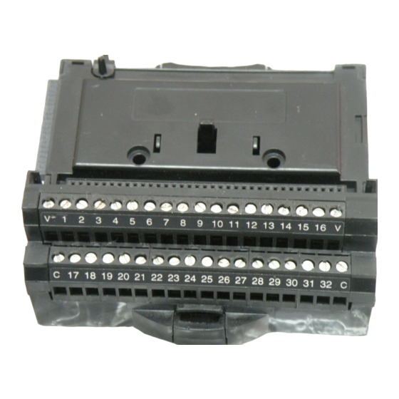
Page 5: Field Wiring
Field Wiring The FP-TB-1 and FP-TB-2 provide four dedicated terminals and 32 numbered terminals defined by the I/O module. The four dedicated terminals are two V and two C terminals, one of each at both ends of the terminal base. - Page 6 Connecting Wires to the FP-TB-1 or FP-TB-3 Follow these steps to connect wires to the FP-TB-1 or FP-TB-3. 1. Unscrew the terminal screw you want to wire. 2. Insert the wire.
- Page 7 10 A. If you have a single external supply for the field devices of more than one module, wire the supply to the V and C terminals as shown in Figure 8. © National Instruments Corp. FP-TB-1/2/3 Operating Instructions...
- Page 8 When total current draw is less than 3 A, you can use a single terminal for the return path. If the total current draw is greater than 3 A, you should use separate C terminals, as shown in Figure 9. FP-TB-1/2/3 Operating Instructions ni.com...
- Page 9 • You may want to use separate power supplies for I/O modules both to prevent power dips caused by field devices from disrupting the operation of the network module and to maintain © National Instruments Corp. FP-TB-1/2/3 Operating Instructions...
-
Page 10: Thermocouple Wiring
The thermal gradient generated across the terminals can cause the terminals of different channels FP-TB-1/2/3 Operating Instructions ni.com... - Page 11 Adjacent FieldPoint modules (either network modules or I/O modules) create a thermal gradient across the terminals of the FP-TB-1, which you can estimate by dividing the larger of the amounts of heat dissipated by each of the adjacent modules by 1 Watt/°C (0.6 Watts/°F).
- Page 12 Minimizing Thermal Gradients The most common source of thermal gradients, particularly for the FP-TB-1 and FP-TB-2, is the heat generated by adjacent modules. For example, placing an FP-TB-1 next to an FP-1000 network module can create more than a 1 °C thermal gradient. Mounted...
-
Page 13: Specifications
Figure 12. Conductor Wire with the Correct Strip Length Torque for screw terminals ....0.5-0.6 Nm (4.4-5.3 in.-lb) Physical Weight FP-TB-1........210 g (7.4 oz) FP-TB-2........160 g (5.7 oz) FP-TB-3........240 g (8.5 oz) Maximum Working Voltage Maximum working voltage refers to the signal voltage plus the common-mode voltage. - Page 14 To obtain the DoC for this product, click Declaration of Conformity at ni.com/hardref.nsf/ Mechanical Dimensions Figure 13 show the mechanical dimensions of the FP-TB-1/2/3 with an I/O module installed. Dimensions are given in millimeters [inches]. 107.19 [4.22] 109.5...
-
Page 15: Where To Go For Support
Where to Go for Support For more information about setting up your FieldPoint system, refer to these National Instruments documents: • Your FieldPoint network module user manual • Your other FieldPoint I/O module operating instructions • Your FieldPoint terminal base operating instructions...
Need help?
Do you have a question about the FP-TB-1 and is the answer not in the manual?
Questions and answers