Table of Contents
Advertisement
Quick Links
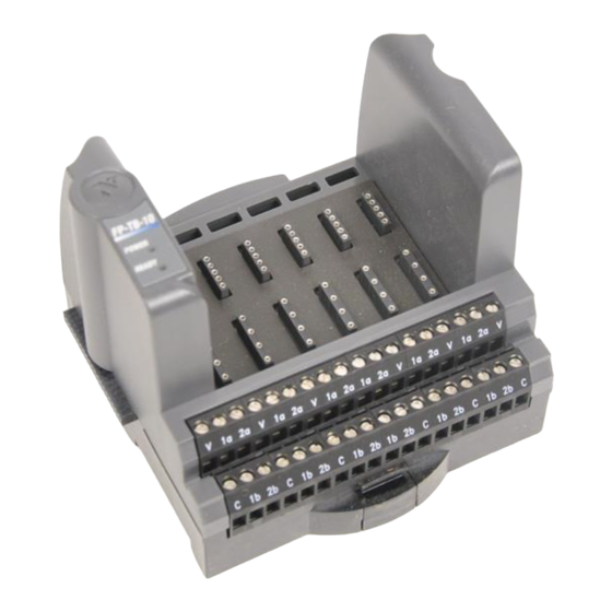
FieldPoint Operating Instructions
FP-TB-10
Terminal Base and Dual-Channel
FieldPoint Modules
These operating instructions describe the installation, features, and
characteristics of the FP-TB-10 terminal base and of the various
dual-channel modules that work with it. For details on configuring
and accessing these modules over a network, refer to the user
manual for the particular FieldPoint network module you are using
with the dual-channel system.
Features
The FP-TB-10 and the dual-channel FieldPoint modules have the
following features:
•
High granularity of system design with up to six dual-channel
I/O modules per terminal base
•
Any combination of I/O types in each terminal base
•
Independent isolation of each dual-channel I/O module
FieldPoint dual-channel I/O modules offer maximum flexibility in
configuring I/O systems. You can mount up to six dual-channel
modules in any combination on the FP-TB-10 terminal base. You
can mix dual-channel modules with standard eight- and 16-channel
modules in a single FieldPoint bank. Therefore, you can configure
your FieldPoint system to match your specific I/O needs,
minimizing the size and cost of your distributed I/O system. In
addition, the dual-channel modules provide a flexible solution for
applications requiring channel-to-channel isolation.
FieldPoint™, National Instruments™, NI™, and ni.com™ are trademarks of National Instruments Corporation.
Product and company names mentioned herein are trademarks or trade names of their respective companies.
For patents covering National Instruments products, refer to the appropriate location: Help»Patents in your software,
the patents.txt file on your CD, or ni.com/patents .
322717C-01
© 2000–2002 National Instruments Corp. All rights reserved.
June 2002
Advertisement
Table of Contents

Related Manuals for National Instruments FieldPoint FP-TB-10


Summary of Contents for National Instruments FieldPoint FP-TB-10
- Page 1 FieldPoint™, National Instruments™, NI™, and ni.com™ are trademarks of National Instruments Corporation. Product and company names mentioned herein are trademarks or trade names of their respective companies. For patents covering National Instruments products, refer to the appropriate location: Help»Patents in your software, the patents.txt file on your CD, or ni.com/patents .
- Page 2 Mounting the Terminal Base on a DIN Rail Before you connect a terminal base to a network Note module, the network module must be powered off. 1. With a flathead screwdriver, open the rail clip to the unlocked position as shown in the following figure. Figure 1.
- Page 3 Figure 4. Snapping the Panel-Mount Accessory onto the Terminal Base 3. Lock the rail clip. 4. Mount the FP-TB-10 and panel-mount accessory onto the desired surface. You can drill pilot holes using the directions in the panel-mount adapter installation guide. © National Instruments Corp. FP-TB-10 Operating Instructions...
- Page 4 Install the network module first, using two bolts or screws, then install the FP-TB-10 using the right bolt tab. If you use a FieldPoint bus extender cable, the first FP-TB-10 on the new row should use both panel-mount bolt tabs. Installing Dual-Channel I/O Modules You can install up to six dual-channel modules on each FP-TB-10 terminal base.
-
Page 5: Field Wiring
V and C terminals in order to use the dual-channel modules. Figure 6. Module Slots and the Screw Terminals Associated with Them © National Instruments Corp. FP-TB-10 Operating Instructions... -
Page 6: Update Rates
Some dual-channel modules, such as the thermocouple and four-wire RTD modules, provide other means of making field-wiring connections. Update Rates The FP-TB-10 continuously scans through its six dual-channel modules, updating outputs and reading inputs. The scan rate varies depending on the modules in the FP-TB-10. Empty slots and digital modules add 0.2 ms each to the scan time, and analog modules add 1.5 ms each. - Page 7 Current FP-AI-C xxx FP-AI-C xxx Current Source Source 133 Ω 133 Ω – Loop Supply 133 Ω 400 kΩ 133 Ω (FP-AI- C420 Only) Figure 7. Analog Current Input Module Signal Connections © National Instruments Corp. FP-TB-10 Operating Instructions...
- Page 8 Analog Voltage Input Modules (FP-AI-V50m, FP-AI-V100m, FP-AI-V1, FP-AI-V5, FP-AI-V5B, FP-AI-V10, and FP-AI-V10B) The FP-AI-V50m, FP-AI-V100m, FP-AI-V1, FP-AI-V5, FP-AI-V5B, FP-AI-V10, and FP-AI-V10B are dual-channel analog voltage input modules that provide 12-bit-resolution measurements. Each channel has a programmable filter with two settings, 20 Hz bandwidth and 2 kHz bandwidth. The two channels share a common reference point, the “b”...
- Page 9 The FP-RTD-PT100 connects to two FP-TB-10 screw terminals per channel. The “b” terminal is common for both channels. The FP-RTD-PT100-3 has two sets of screw terminals on top and does © National Instruments Corp. FP-TB-10 Operating Instructions...
- Page 10 not connect to the screw terminals on the FP-TB-10. A legend on the side of the module shows the names of the terminals. The following diagram shows which screw terminals to use for each module. FP-RTD-PT100-3 FP-RTD-PT100 3-wire 100 µA 2.5 V 2-wire 4.53 kΩ...
- Page 11 FP-AO-C xxx Current flow Load (500 Ω max) Figure 12. Connecting an Analog Current Output Module to a Load © National Instruments Corp. FP-TB-10 Operating Instructions...
- Page 12 Analog Voltage Output Modules (FP-AO-V5, FP-AO-V5B, FP-AO-V10, and FP-AO-V10B) The FP-AO-V5, FP-AO-V5B, FP-AO-V10, and FP-AO-V10B are dual-channel analog voltage output modules that provide 12-bit-resolution measurements. The power supplies in these modules can drive loads with up to 20 mA of current; however, each channel has 10 Ω...
- Page 13 FP-DI-DC FP-DI-DC Sourcing Device – Sinking Device – Figure 14. Connecting Sourcing and Sinking Devices to the FP-DI-DC FP-DI-AC xxx 25–70 Hz Load Figure 15. Wiring Diagram for Discrete AC Input Modules © National Instruments Corp. FP-TB-10 Operating Instructions...
- Page 14 Discrete Output Modules (FP-DO-DC60, FP-DO-DC200, FP-DO-AC120, and FP-DO-AC240) The FP-DO-DC60, FP-DO-DC200, FP-DO-AC120, and FP-DO-AC240 are discrete output modules. Each module has two isolated channels, so applications requiring channel-to-channel isolation can use both channels on each module. Each module has two green indicator LEDs, one for each channel, to indicate whether the channel is in the ON or the OFF state.
- Page 15 IEC 61010-1) for working common-mode voltages of 250 V Safety standards (such as those published by UL and IEC) require the use of double insulation between hazardous voltages and any human-accessible parts or circuits. © National Instruments Corp. FP-TB-10 Operating Instructions...
- Page 16 Never try to use any isolation product between human-accessible parts (such as DIN rails or monitoring stations) and circuits that can be at hazardous potentials under normal conditions, unless the product is specifically designed for such an application, as is the FP-TB-10.
-
Page 17: Specifications
Step response time Voltage and current inputs..1.5 ms RTD inputs ......... 42 ms Thermocouple inputs....100 ms Input protection Current inputs ......38 mA Voltage inputs ......±30 V Thermocouple, RTD....±6 V © National Instruments Corp. FP-TB-10 Operating Instructions... -
Page 18: Analog Output Modules
Table 1. Analog Input Module Accuracy Input Resolu- Accuracy Temperature Module Range tion (at 25 °C) Drift* 12.2 µV ±0.07% 1.8 µV + 75 ppm FP-AI-V50m 0 to 50 mV 24.4 µV ±0.07% 3.5 µV + 75 ppm FP-AI-V100m 0 to 100 mV 244 µV ±0.075% 35 µV + 75 ppm... -
Page 19: Discrete Output Modules
Delay time (max) 0.4 ms 20 ms 20 ms Discrete Output Modules Number of channels......Two isolated outputs Replaceable fuses (5 × 20 mm, 3.15 A, 250 V, fast-acting) FP-DO-DC, FP-DO-AC ..... Littelfuse 217315 © National Instruments Corp. FP-TB-10 Operating Instructions... -
Page 20: Power Requirements
Table 4. Discrete Output Characteristics FP-DO- FP-DO- FP-DO- FP-DO- DC60 DC200 AC120 AC240 Voltage 3 to 60 VDC 4 to 200 VDC 24 to 140 VAC 24 to 280 VAC range 25 to 70 Hz 25 to 70 Hz Voltage 1.3 V at 0.75 A 1.75 V at 1.0 A 1.0 V at 0.5 A... -
Page 21: Physical Characteristics
[93.22] Figure 18. Mechanical Dimensions of the FP-TB-10 Where to Go for Support For more information about setting up your FieldPoint system, refer to these National Instruments documents: • Your FieldPoint network module user manual • Your other FieldPoint I/O module operating instructions •... - Page 22 Go to for the most current manuals, examples, ni.com/support and troubleshooting information. For telephone support in the United States, create your service request at and follow the calling instructions or dial ni.com/ask 512 795 8248. For telephone support outside the United States, contact your local branch office: Australia 03 9879 5166, Austria 0662 45 79 90 0, Belgium 02 757 00 20, Brazil 011 284 5011,...
Need help?
Do you have a question about the FieldPoint FP-TB-10 and is the answer not in the manual?
Questions and answers