Table of Contents
Advertisement
Quick Links
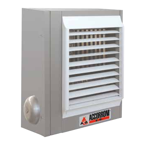
Axial and centrifugal condensation hanging hot air generators
with pre-mixed modulating gas burner
MEC MIX C
modulating condensation
MEC MIX F
fixed power
MADE
CONDENSATION
CONDENSING
REMOTE
HIGH
COMBUSTION
IN ITALY
SYSTEM
PREMIXED BURNER
OF SERIES
PERFORMANCE 104%
ROOM IN
CERTIFICATED
STAINLESS STEEL
1
Advertisement
Table of Contents

Summary of Contents for a2b ACCORRONI MEC MIX C Series
- Page 1 Axial and centrifugal condensation hanging hot air generators with pre-mixed modulating gas burner MEC MIX C modulating condensation MEC MIX F fixed power MADE CONDENSATION CONDENSING REMOTE HIGH COMBUSTION IN ITALY SYSTEM PREMIXED BURNER OF SERIES PERFORMANCE 104% ROOM IN CERTIFICATED STAINLESS STEEL...
-
Page 2: Table Of Contents
The entry into force of new provisions or changes to those in force will not constitute a reason for any obligation of A2B Accorroni E.G. - Page 3 Dimensions and dimensions MEC MIX C with condensation 20/35 - 20/45 with axial fans ....9 Dimensions and dimensions MEC MIX F 35 - 50 with axial fans ............9 Dimensions and dimensions MEC MIX C condensation 20/70 - 20/90 with centrifugal fans ....10 Dimensions and dimensions MEC MIX F 70 - 100 with centrifugal fans ..........
-
Page 4: General Warnings
SEZIONE A - INFORMAZIONI GENERALI 2.5 USE 1. GENERAL WARNINGS This manual is an integral part of the product, it should The use of the appliance should not be allowed to children, inexperienced persons and unassisted not be separated from it and must be kept carefully for any future use or consultation. -
Page 5: Main Characteristics
generator modulation. 3. MAIN FEATURES 3.1 FUNCTIONAL DESCRIPTION In the event of obstructions or malfunctions beyond The MEC MIX series hot air generator is an independent the permitted temperature, a flue gas thermostat will heating device of type atin circuit. then cause the gas valve to stop and the generator to The appliance belonging to the II2H3P category shut down. -
Page 6: Table Of Mec Mix C Axial Condensation Technical Data
3.3 Technical data table MEC MIX C axial DESCRIPTION MEC MIX C 20/35 A MEC MIX C 20/45 A MEC MIX C 20/70 A MEC MIX C 20/90 A U.M. Equipment category 2H3P Type of device B23 - C13 - C33 - C63 - C53 Gas supplies Gas Naturale - G.P.L. -
Page 7: Centrifugal Condensing Mec Mix C Technical Data Table
3.5 Technical data table MEC MIX C centrifuge DESCRIPTION MEC MIX C 20/35 C MEC MIX C 20/45 C MEC MIX C 20/70 C MEC MIX C 20/90 C U.M. equipment category 2H3P Type of device B23 - C13 - C33 - C63 - C53 Gas supplies Natural Gas - G.P.L. -
Page 8: Dimensions And Dimensions Mec Mix C Condensing 20/35 - 20/45 With Centrifugal Fans
3.7 DIMENSIONS AND DIMENSIONS Series MEC MIX C condensing models 20/35 - 20/45 with centrifugal fans MEC MIX F series models 35 - 50 with centrifugal fans view from above connection air intake exhaust exhaust* Values expressed in mm * The drain siphon is only available in the condensing MEC MIX C series... -
Page 9: Dimensions And Dimensions Mec Mix C With Condensation 20/35 - 20/45 With Axial Fans
3.8 DIMENSIONS AND DIMENSIONS Series MEC MIX C condensing models 20/35 - 20/45 with axial fans MEC MIX F series models 35 - 50 with axial fans view from above connection air intake exhaust exhaust* Values expressed in mm * The drain siphon is only available in the condensing MEC MIX C series... -
Page 10: Dimensions And Dimensions Mec Mix C Condensation 20/70 - 20/90 With Centrifugal Fans
3.9 DIMENSIONS AND DIMENSIONS Series MEC MIX C condensing models 20/70 - 20/90 with centrifugal fans Series MEC MIX F models 70 - 100 with centrifugal fans connection connection combustion combustion air intake air intake exhaust exhaust fumes fumes Values expressed in mm... -
Page 11: Dimensions And Dimensions Mec Mix C Condensing 20/70 - 20/90 With Axial Fans
3.10 DIMENSIONS AND DIMENSIONS MEC MIX C series condensing models 20/70 - 20/90 with axial fans MEC MIX F series 70 - 100 models with axial fans connection connection combustion combustion air intake air intake exhaust exhaust fumes fumes Values expressed in mm... -
Page 12: Wiring Diagram - Mec Mix C / F Series
3.11 ELECTRICAL DIAGRAM - MEC MIX C / F Series LEGEND ACC1 Remote ignition transformer FAN1 Fan motor 1 treated air C1 Capacitor 1 (5μF) FAN2 Fan motor 2 treated air C2 Capacitor 2 (5μF) GA1 Programmable thermostat EA Ignition electrode ION Detection electrode EF Burner fan motor M1 Terminal block 1... -
Page 13: Control And Security Bodies
SECTION B - USER 4. CONTROL AND SECURITY BODIES - management of a double NTC probe type ST08 In this section you will find all the necessary for the control of the delivery temperature information to make it work properly MEC MIX air for regulation functions;... -
Page 14: Checks On Commissioning
Pre-ignition time (option Jnn): 1 ... 60 s On request, the behavior of the equipment in case Cycle repetition attempt of opening of the contact can be modified according (option Ynn): 1 ... 10 to customer specifications. Maximum cable length of external components: OpenTherm ™... -
Page 15: Kronos Ga11 Chronothermostat
The communication between the chronothermostat 5. KRONOS GA11 5.1 WEEKLY-PROGRAMMING DIGITAL (master) and the control board (slave) of hot air CHRONOTHERMOSTAT FOR THE REMOTE generators takes place by means of a two-wire cable. CONTROL OF HOT AIR GENERATORS Particulary, the data, between the chronothermostat THROUGH INTERFACE BOARD and the control board of the first generator, are exchanged... -
Page 16: Instructions For Use
5.4 INSTRUCTION FOR USE Then the current time can be entered. The Kronos GA11 provides the user with a graphic LCD dot-matrix, a series of buttons in silicon rubber, and an LED indicator located below a button plastic transparent to display the parameters and interact with the heating system. -
Page 17: Corrispondence Between Icons And Operation Modes
5.6 CORRISPONDENCE BETWEEN ICONS AND The buttons on the right, marked with + and -, allow OPERATION MODES: to vary the temperatures required for the automatic program (T0, T1, T2, T3). Instead, in “manual mode” (icon ) allow to vary the set point room temperature. Pushing the buttons on the left, marked with arrows, you Temperature control can browse the pages of first level menu. - Page 18 In this scren, it is possible to limit the power level required by the chronothermostat to generators, for heating the environment. For more details see the next section, in particular the description of the submenu “Thermoregulation”. Pushing again button ▼ is proposed the submenu “PARAMETERS MENU”...
-
Page 19: Management Chronothermostat Setting Menu
To select the temperature level is necessary to push the buttons ↓ e ↑, instead to vary the temperature value it is necessary to push + e –. On the right side of the screen is shown the relative position of the current setpoint temperature value with respect to minimum values (5 °C) and maximum value (30 °C). - Page 20 In the second step, pushing the ◄ and ► you select Pushing the OK button, you confirm the changes. which of the four programmed temperatures will be The “Language” submenu on the “SETTING MENU” associated to the time slot. allows set the language of texts on the chronothermostat. Pushing OK you confirm the level of temperature and pushing ESC you return in the first step.
-
Page 21: Management System Parameters Menu
Example 2: Ti = 20,0 ºC Max = 100% d = 0,9 ºC hysteresis = 0,4 ºC (hysteresis can vary between 0,1ºC e diff / 2 = 0,4 ºC) When Ta ≥ 20ºC then P = 0, and the generators are turned off. -
Page 22: Specific Functions Kronos Ga11
6. SPECIFIC FUNCTIONS KRONOS GA11 6.1 INTERNAL ENERGY STORE AND USE OF BATTERIES The chronothermostat is provided with an internal energy store which can compensate for a power cut-off for a few hours; in this way the user will not have to set the current time, room temperatures and week program again. -
Page 23: Installing The Chrothermostat On The Wall
6.4 INSTALLING THE CHROTHERMOSTAT Instructions for unhooking the front panel ON THE WALL 1) Press PUSH button First step, remove the cover containing the electronic 2) Rotate upwards board by pushing the appropriate button trapezoid, that says “PUSH”, located on the lower unit and rotating the cover itself up, until it is fully removed, as shown in figure 3. -
Page 24: Wiring Diagram For Brahma Equipment Type Tc340P
6.6 WIRING DIAGRAM FOR BRAHMA EQUIPMENT TYPE TC340P Fig. 12 Legend Thermostat Burner fan motor Treated air blower motor ACC1 Auxiliary remote ignition transformer Valve first stage Adjustment probe Fire damper Room sensor (optional) Signaling brightness and LEDs RESET Outlet button Connection for cascaded equipment Detection electrode... -
Page 25: Connection Diagram For Cascade Connections More Devices Through Open Therm
6.7 CONNECTION DIAGRAM FOR CASCADE CONNECTIONS MORE DEVICES THROUGH Open Therm NOTE 1. The cascade connection is also possible through contact chronothermostat. this configuration is not used in versions TC340P1 Fig. 13... -
Page 26: Types 0F Connection
6.8 TYPES OF CONNECTION The following are all connection types... -
Page 27: Installation
- To the UNI CIG 7131 standard that regulates the heating system components. installation of appliances powered by LPG In any case, by calling the Presale office of A2B - To the UNI 11071 standard that regulates the Accorroni E.G. srl (phone +39.071.723991) you can installation of heat generators a condensation. -
Page 28: Installation Sequence
DISTANCES OF RESPECT MEC MIX C CENTRIFUGES A min 200 cm B min 250 cm max. 350 cm C min 40 cm D min 50 cm E min 33 cm OBJECT STRUCTURE Fig.15 B Fig. 15 B the mouth of sent could affect the present staff in the smoke outlet and the combustion air intake. -
Page 29: Dimensioning Of Air Tubes Comburente / Fumes Discharge
POSITIONING EXAMPLES Fig.16 7.3 DIMENSIONING OF AIR TUBES room in which it is installed. COMBURENTE / FUMES DISCHARGE - C63 type installation: this type allows to realize MEC MIX series hot air generators can be installed in fume exhaust / air sampling systems using tubes, one of the following ways: curves and terminals retrieved from trade, provided - installation type C13: product unloading of... -
Page 30: Calculation Example
The equivalent lengths of special pieces, like curves EXAMPLE OF FUME EXHAUST PIPE with various angles are shown in table 13. The load losses of the external terminals can be neglected because they are very low. In the design phase it is necessary to verify that the equivalent total length is less than or equal to the maximum possible length as shown in figures 18÷28. - Page 31 INSTALLATION TYPE C13 - SEPARATED WALL TUBES Ø 60 MAXIMUM ADMISSION LENGTHS (m) Mod. AIR PIPE FUMES TUBE WARNING! the aforesaid lengths are to be understood in the case of installations in which the air tube and the flue pipe carry out a linear path as shown in the figure. Otherwise it is necessary to proceed with the calculation of the load loss check Fig.
- Page 32 Fig. 20 (see EXAMPLE OF CALCULATION). INSTALLATION TYPE C53 - SEPARATED WALL TUBLES Ø 60 MAXIMUM ADMISSION LENGTHS (m) Mod. AIR PIPE FUMES TUBE WARNING! the aforesaid lengths are to be understood in the case of installations in which the air tube and the flue pipe carry out a linear path as shown in the figure. Otherwise it is necessary to proceed with the calculation of the load loss check Fig.
- Page 33 Fig. 23 (see EXAMPLE OF CALCULATION). INSTALLATION TYPE B23 - TUBES Ø 80 MAXIMUM ADMISSION LENGTHS (m) Mod. FUMES TUBE WARNING! the aforesaid lengths are to be understood in the case of installations in which the air tube and the flue pipe carry out a linear path as shown in the figure. Otherwise it is necessary to proceed with the calculation of the load loss check Fig.
-
Page 34: Conduct Evacuation
Fig. 26 (see EXAMPLE OF CALCULATION). INSTALLATION TYPE C33 - ROOF COAXIL EXHAUST FUMES Ø 60/100 MAXIMUM ADMISSION LENGTHS (m) Mod. COAXIAL TUBE WARNING! the aforesaid lengths are to be understood in the case of installations in which the air tube and the flue pipe carry out a linear path as shown in the figure. Otherwise it is necessary to proceed with the calculation of the load loss check Fig. -
Page 35: Installation
SECTION D - ELECTRIC INSTALLATION 8. INSTALLATION shielding of cables or by laying in raceways In this section you will find all the information separate from those in which cables are used necessary to electrically connect the MEC MIX series power. -
Page 36: Assistance And Maintenance
SECTION E - ASSISTANCE AND MAINTENANCE 9. ASSISTANCE AND MAINTENANCE change procedure (paragraph 8.3) and the relative 9.1 FIRST START-UP OF THE APPLIANCE regulation of the parameters (paragraph 8.2). The first ignition must be carried out exclusively by an authorized Technical Assistance Center or by 9.2 HOW TO MAKE THE ADJUSTMENT OF THE professionally qualified personnel. - Page 37 GAS REGULATION VALVE Fig. 31 !"#$%&!'(")*+,$-"(-& LEGEND Air signal connection EV1 solenoid valve Adjustment of O (offset) EV2 solenoid valve Adjustment of the ratio (opt.) Inlet pressure outlet Pilot output (optional) Pint outlet pressure outlet 10 Main gas outlet P. of additional outlet pressure 11 Side exit Adjustment of the gas valve value if necessary.
-
Page 38: How To Change Gas
The adjustment operation of the gas valve must be Table n. 16 carried out by professionally qualified personnel. CO2 VALUES FOR METHANE GAS In this regard A2B srl has a network of Assistance VALVE ADJUSTMENT Points that can be reached through the seller, the METHANE... -
Page 39: Technical Data Tables Erp
10. TABLE OF TECHNICAL DATA ERP 10.1 TABLE OF TECHNICAL DATA ERP - MEC MIX C 20/35 - 20/90 AXIALS η η η η s,on -10% + F(1) + F(2) + F(3) - F(4) - F(%) s,on -10% + F(1) + F(2) + F(3) - F(4) - F(%) Type of device: Heaters of gaseous fuel closed... -
Page 40: Table Of Erp Technical Data - Mec Mix C 20/35 - 20/70 Centrifuges
10.2 TABLE OF TECHNICAL DATA ERP - MEC MIX C 20/35 - 20/70 CENTRIFUGES η η η η s,on -10% + F(1) + F(2) + F(3) - F(4) - F(%) s,on -10% + F(1) + F(2) + F(3) - F(4) - F(%) Type of device: Heaters of gaseous fuel closed... -
Page 41: Technical Data Table Erp - Mec Mix C 20/45 - 20/90 Axial
10.3 TABLE OF TECHNICAL DATA ERP - MEC MIX C 20/45 - 20/90 AXIAL η η η η s,on -10% + F(1) + F(2) + F(3) - F(4) - F(%) s,on -10% + F(1) + F(2) + F(3) - F(4) - F(%) Type of device: Heaters of gaseous fuel closed... -
Page 42: Table Of Technical Data Erp - Mec Mix C 20/45 - 20/90 Centrifuges
10.4 TABLE OF TECHNICAL DATA ERP - MEC MIX C 20/45 - 20/90 CENTRIFUGES η η η η s,on -10% + F(1) + F(2) + F(3) - F(4) - F(%) s,on -10% + F(1) + F(2) + F(3) - F(4) - F(%) Type of device: Heaters of gaseous fuel closed... -
Page 43: Technical Data Table Erp - Mec Mix F 35 - 70 Axial
10.5 TABLE OF TECHNICAL DATA ERP - MEC MIX F 35 - 70 AXIAL η η η η s,on -10% + F(1) + F(2) + F(3) - F(4) - F(%) s,on -10% + F(1) + F(2) + F(3) - F(4) - F(%) Type of device: Heaters of gaseous fuel closed... -
Page 44: Table Of Technical Data Erp - Mec Mix F 35 - 70 Centrifuges
10.6 TABLE OF TECHNICAL DATA ERP - MEC MIX F 35 - 70 CENTRIFUGES η η η η s,on -10% + F(1) + F(2) + F(3) - F(4) - F(%) s,on -10% + F(1) + F(2) + F(3) - F(4) - F(%) Type of device: Heaters of gaseous fuel closed... -
Page 45: Technical Data Table Erp - Mec Mix F 50 - 100 Axial
10.7 TABLE OF TECHNICAL DATA ERP - MEC MIX F 50 - 100 AXIAL η η η η s,on -10% + F(1) + F(2) + F(3) - F(4) - F(%) s,on -10% + F(1) + F(2) + F(3) - F(4) - F(%) Type of device: Heaters of gaseous fuel closed... -
Page 46: Technical Data Table Erp - Mec Mix F 50 - 100 Centrifuges
10.8 ABLE OF TECHNICAL DATA ERP - MEC MIX F 50 - 100 CENTRIFUGES η η η η s,on -10% + F(1) + F(2) + F(3) - F(4) - F(%) s,on -10% + F(1) + F(2) + F(3) - F(4) - F(%) Type of device: Heaters of gaseous fuel closed... -
Page 47: Main Requirements Of Hot Air Generators
Seasonal energy efficiency of space heating µs,h 92,5 Contact A2B ACCORRONI E.G. Via d’Ancona, 37 - 60020 Osimo (AN) (*) not required for electric hot air generators (**) from 26 September 2018 11.2 TABLE REQUIREMENTS MAIN MEC MIX C 20/35 - 20/70 CENTRIFUGES... -
Page 48: Table Of Main Requirements - Mec Mix C 20/45 - 20/90 Axial
Seasonal energy efficiency of space heating µs,h 92,1 Contact A2B ACCORRONI E.G. Via d’Ancona, 37 - 60020 Osimo (AN) (*) not required for electric hot air generators (**) from 26 September 2018 11.4 TABLE OF MAIN REQUIREMENTS MEC MIX C 20/45 - 20/90 CENTRIFUGES... -
Page 49: Table Of Main Requirements - Mec Mix F 35 - 70 Axial
Seasonal energy efficiency of space heating µs,h Contact A2B ACCORRONI E.G. Via d’Ancona, 37 - 60020 Osimo (AN) (*) not required for electric hot air generators (**) from 26 September 2018 11.6 TABLE OF MAIN REQUIREMENTS MEC MIX F 35 - 70 CENTRIFUGES... -
Page 50: Table Of Main Requirements - Mec Mix F 50 - 100 Axial
Seasonal energy efficiency of space heating µs,h Contact A2B ACCORRONI E.G. Via d’Ancona, 37 - 60020 Osimo (AN) (*) not required for electric hot air generators (**) from 26 September 2018 11.8 TABLE OF MAIN REQUIREMENTS MEC MIX F 50 - 100 CENTRIFUGES... - Page 51 DECLARATION OF CONFORMITY Manufacturer: A2B Accorroni E.G. srl Address: 60027 Osimo (AN) - Via D’Ancona, 37 Tel 071/723991 - Fax 071/7133153 VAT and C.F. 02345650424 Unit: Independent forced gas heating appliances with forced air-gas premixer Type: MEC MIX Model: C20 / 35 axial, C20 / 45 axial, C20 / 70 axial, C20 / 90 axial, C20 / 35...
- Page 52 Via d’Ancona, 37 - 60027 Osimo (An) - Tel. 071.723991 web site: www.accorroni.it - e-mail: a2b@accorroni.it NB - I dati riportati nel presente manuale tecnico sono forniti a titolo puramente indicativo, la A2B Accorroni E.G. S.r.l. si riserva di apportare eventuali modifiche senza alcun preavviso...
Need help?
Do you have a question about the ACCORRONI MEC MIX C Series and is the answer not in the manual?
Questions and answers