
Related Manuals for Gamma Vacuum SPCe


Summary of Contents for Gamma Vacuum SPCe
- Page 1 SMALL PUMP CONTROLLER (SPCe) USERS MANUAL PN 900026, Rev E ISO 9001:2015 Certified...
-
Page 2: General Information
Gamma Vacuum Small Pump Controllers (SPCe) are shown to meet The SPCe can be controlled two ways: directly from the front panel the EEC Low-Voltage Directive and Electromagnetic Compatibility or remotely through serial or Ethernet ports. The serial port supports approvals: RS-232/422/485 protocols. -
Page 3: Unpacking The Controller
• The SPCe can be mounted in a standard 19 in. (48.3 cm) rack or If the SPCe is damaged in any way, a claim should be filed with the used as a free-standing unit. carrier immediately and notification given to Gamma Vacuum. -
Page 4: Operation
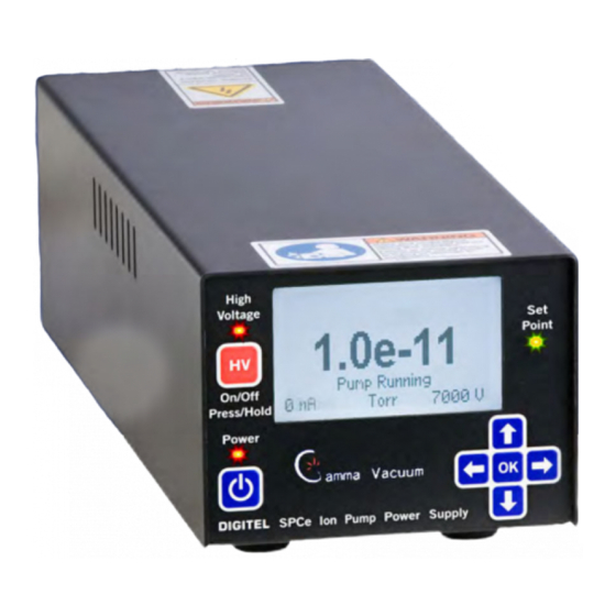
If the ion pump size has not been entered into the System Menu, LED Indicators and LCD Display enter the ion pump size. The SPCe will not start until the ion pump LEDs indicate the status of the main power, high voltage, and the set size has been entered. -
Page 5: Display Menu
Operation parameters, messages, and menu options are shown on the LCD display. Display During Ion Pump Operation When the ion pump is in operation, the SPCe displays voltage, current, and pressure. Size The Size parameter must be set prior to high voltage operation. - Page 6 Setpoint is active, the Setpoint will remain active independent of the pressure thereafter. • Error: The Setpoint will turn on when the SPCe has an error condition. NOTE: If an asterisk (*) is present, a pump size has not been entered into the controller.
- Page 7 • Current: 1VDC per 1nA • Current: 1VDC per 100uA Normally, when DC power is applied to the SPCe, the SPCe does not start until the Power button is pressed. In the case where power • Current: 1VDC per 10nA •...
- Page 8 +22 to +26VDC range in order to run HV. • Enabled: The input power voltage can be outside this range. Address This parameter is used to set the SPCe serial address. The default value is 5. Communications Mode (Comm) Handshaking This parameter is used to set serial handshaking.
- Page 9 Baud Rate (Baud) DHCP & IP Address (Addr) This parameter is used to set the serial baud rate of the SPCe. The The SPCe is capable of acting as a DHCP (Dynamic Host default value is 115200. Configuration Protocol) client. When enabled as a DHCP client, the SPCe will obtain needed network information from a DHCP server.
-
Page 10: Configuration Menu (Config)
LCD Timeout The SPCe’s LCD back light can be dimmed to extend the life of the display. By enabling this parameter, the back light is dimmed after a specified amount of time has passed since the last key press. This feature is off by default. - Page 11 (for example after a long turbo bake). Update Firmware (Update) The SPCe firmware can be updated via serial cable or ethernet. The latest version of SPCe software is downloadable from www.gammavacuum.com. Reference Service Bulletin 00.056.092 in that download for full details.
-
Page 12: Display Message
DISPLAY MESSAGES During operation, the SPCe may detect and report a number of possible operating conditions. For example, the SAFECONN connector may become disconnected, the vacuum may fail, or the ion-pump may have a problem. These conditions are reported by the following messages... -
Page 13: Back Panel Operation
The SPCe unit is in error mode. Logarithmic Pressure (p) Examples NOTE: There is a delay after turning on the HV until the SPCe Example 1 considers the calculated pressure reading to be valid. This Offset = 10 reading can take up to one minute. The setpoint relay will... -
Page 14: Ethernet Connector
13 is pulled up to +14V through a 4K7 resistor. A Telnet session may be established to port TCP 23, allowing remote control of the SPCe in the same way as serial communications link. Pin 13 Once the Telnet session is established, commands may be issued in the format: spc <two-digit command code>... - Page 15 Cabling The SPCe functions as a DTE (Data Terminal Equipment) device. When the controller is connected to another DTE device (such as a personal computer), a null modem serial cable is required to connect the devices.
-
Page 16: Command Packet Structure
Start is the first byte in the command packet and tells remote controllers to start decoding a message. It should be implemented as a #define, so it can be changed if necessary. As a #define, the character is rarely changed because it is hard coded into the SPCe. - Page 17 Decoding the Command Packet An SPCe operates in one of three modes: monitor, receive, and respond. Receipt of data is interrupt driven or otherwise multiplexed, so other tasks are performed by the unit’s microprocessor. When the controller receives a command packet, it continues monitoring for new commands while the current one is carried out.
- Page 18 For an error condition with an incoming command, this field returns an error number to the controlling computer. For non-error conditions, this field returns a status byte/word to the controlling computer, which is defined in the SPCE and can vary with the needs of individual commands within a unit, as well as varying from unit to unit.
- Page 19 RS 232/422/485 General Commands Description Data Response Data/Response Command Field Description MODEL NUMBER DIGITEL SPCe A description of the controller. VERSION DIGITEL X.XX is the numerical revision level for Firmware revision level. FIRMWARE: X.XX major changes MASTER RESET No response due to initialization of Executes a complete software reset.
- Page 20 Displays the mode of Auto Recovery. 0 = disabled 1 = enable auto HV restart 2 = enable auto power recovery SET_FIRMWARE_UPDATE Sets the SPCe to flash load mode for firmware updates. SET COMM MODE N is the mode Sets the communication mode to local, 0 = Local full, or remote.
- Page 21 Description Data Response Data/Response Command Field Description GET/SET SERIAL COMM None or None or B = baud rate Gets/Sets baud rate, parity, data “B, P, D, S” “B, P, D, S” P = parity (“n”, “e”, “o”) bits, and stop bits. If no parameters (set mode) (get mode) D = data bits (“7”, “8”)
- Page 22 Divide result by 256 and the integer remainder Tx – “~ 01 01 22” + carriage return. converted to two ASCII hex digits is the checksum for the Rx – “01 OK 00 DIGITEL SPCe 48” + carriage return command. Characters...
-
Page 23: Warranty And Service
Cleaning Procedure at Gamma Vacuum’s option and free of parts charge to Buyer, and Prior to any cleaning of the SPCe, the mains power should be part or parts which, under proper and normal conditions of use, disconnected. Once powered off, use a 50% distilled water and prove to be defective within twelve (12) months from the date of 50% isopropyl alcohol solution to clean the entire unit. -
Page 24: Returning Material
Upon notification, Gamma Vacuum will investigate Warranty Claims. To initiate a Warranty Claim, please contact Gamma Vacuum or a representative of Gamma Vacuum directly. To assist in this evaluation, please provide the following information in as much detail as possible: •... -
Page 25: Return Material Authorization Form
RETURN MATERIAL AUTHORIZATION FORM Thank you for taking the time to complete this form. Please complete this form and return to Gamma Vacuum in electronic format (Adobe PDF format [.pdf] preferred), or via fax. Digital signatures are acceptable Assigned RMA:...
Need help?
Do you have a question about the SPCe and is the answer not in the manual?
Questions and answers