Table of Contents
Advertisement
Advertisement
Table of Contents

Summary of Contents for Welbilt Delfield CV5E
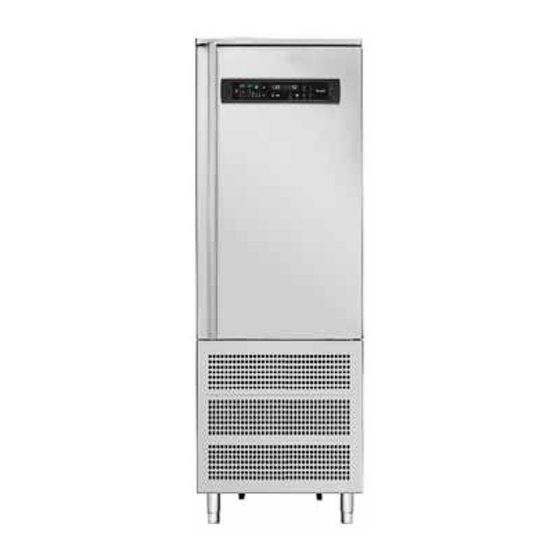
- Page 1 Fresh Solutions, Fit for You Blast Chillers CV5E, CV10E, CV15E, CV15E-2 and T40 Original Instructions Installation, Operation and Maintenance Manual This manual is updated as new information and models are released. Visit our website for the latest manual. Part Number: 9294045 07/19...
-
Page 2: Table Of Contents
1 - WARNINGS AND IMPORTANT ADVICE 16.1 - Evaporator probe alarm 16.2 - Product probe alarm 2 - TECHNICAL DATA 16.3 - Cell probe alarm 16.4 - Door micro-switch alarm 2.1 - Plate data 16.5 - Alarm - Diff. Thermal Breaker - Oil Pressure 2.1 - Refridgerant 16.6 - Auto reset minimum pressure swtich alarm 2.3 - Measurements... - Page 3 Table of Contents 5.2 - Soft blast chilling by temperature 5.3 - Soft timed blast chilling 5.4 - Hard blast chilling by temperature 5.5 - Hard timed blast chilling 5.6 - Blast freezing by temperature 5.7 - Timed blast feezing 6 - APPLIANCE FUNCTIONS 6.1 - Date and time settings 6.2 - Ice cream surface hardening...
- Page 4 Safety Notices Warning Do not use electrical appliances inside the food storage Warning compartments of the appliance, unless they are of the Read this manual thoroughly before operating, installing type recommended by the manufacturer. or performing maintenance on the equipment. Failure to follow instructions in this manual can cause property Warning damage, injury or death.
-
Page 5: Technical Data
Section 2 Technical Information 2 -TECHNICAL DATA 2.1 - Plate data The plate bearing the equipment specifications should be applied on the outside rear part of the machine and/ or on the electrical panels. Any preparation of machines only for relocation of the condensing units must follow the regulations enforced in the country of installation regarding fire safety (refer to the command of the local fire department for the relevent indications). -
Page 6: Measurements
Technical Information Section 2 2.3 - Measurements CV5E - 5 trays CV10E - 10 trays CV15E - 15 trays Part Number: 9294045 07/19... -
Page 7: Maximum Loads
Section 2 Technical Information CV15E-2 - 30 trays Optional internal support structure 2.4 - Maximum load Model Operators are strongly suggested to follow Size Trays enclosed instructions 18” x 26” (655x453mm) 123/4” x 203/4” (530x325mm) 2.4.1 - Maximum load for internal structure capacity 123/4”... -
Page 8: Installation
Technical Information Section 2 3 - INSTALLATION All stages of installation must be carried out in compliance with the national standards in force according to the manufacturer’s instructions and by professionally qualified personnel. Installation of the appliance and of the refrigerating unit must only be carried out by technicians of the manufacturer or by skilled personnel. -
Page 9: Ambient Temperature And Air Exchange
Section 2 Technical Information regulations in the country of installation. Avoid: The electric connecting cables must be dimensioned in accordance with the rules in force in the country of • direct exposure to sunlight; installation. In cases wwhere the power cord of the •... -
Page 10: Commissioning
Technical Information Section 2 • Check the efficient insulation of the connecting pipes 3.13 - Signalling/reports of malfunctioning between the condenser and the remote condensing In cases of malfuntion of the machine and for report unit. signalling concerning the blast chillers supplied. •... -
Page 11: Command Interface Symbols
Section 2 Technical Information 4 - COMMAND INTERFACE SYMBOLS 1 - Stand-by button - Standby button, if pressed for more BLUE - Phase of chilling, deep-freezing or storage ORANGE - Thawing than 3 seconds it takes the card into standby or switches GREEN/BLUE - Machine on stand by it on again. -
Page 12: Machine On/Off
Technical Information Section 2 5 - MACHINE ON/OFF The chilling phase starts upon pressing of the “Start/Stop” button (22) and continues until the end of the chilling When the equipment is powered, it will appear in phase that is used to achieve the time set (Time chilling) or STANDBY conditions (scrolling text on the display). -
Page 13: Chilling Phases
Section 2 Technical Information 7.2 - Chilling phases cooling in the presence of products that are resistant and very hot initially. Pressing the positive chilling button (2) or negative Once the MEDIUM or FAST cycles are started, to modify the chilling button (3) allows selection of a different chilling HARD phase duration simply press the button (2) that will mode. -
Page 14: Storage Phases
Technical Information Section 2 8 - DEFROST MODE Once the cycle to change the duration of the SOFT phase is started (never greater than the parameter C4) simply “Gas-hot” or “air” defrosting takes place: press the button (3) which will show on the display (19) the wording “Soft”... -
Page 15: Ozonator
Section 2 Technical Information 11 - OZONATOR flashing set represented on the display (18) with a value that can range from the minimum value to a maximum This function is only available when the machine is one (this theoretically allows setting of the long softening stopped and is activated by pressing the ozonation cycles for ice-cream which, extracted from the storage button (12) (the LED of the button comes on) . -
Page 16: Chilling Program Storage
Technical Information Section 2 14 - CHILLING PROGRAM STORAGE If the save button is pressed by accident, pressing it again will exit that function. The user has the button (16), which allows the saving or While a program is running, by pressing the “PROG” button recalling of 99 chilling cycles. -
Page 17: Door Micro-Switch Alarm
Section 2 Technical Information and Temperature) or if the latter is already in progress, it Beeper: The beeper sounds (3 seconds and then pauses continues (as it is not conditioned by the cell temperature for 30 seconds) until the silencer button is pressed. until passing into negative storage which will be in pause- Display/LED: The display shows the scrolling text “AL07 work mode (C5 and C7 parameters)). -
Page 18: Black-Out Alarm
Technical Information Section 2 deactivated. All the inputs are ignored. The LED comes on with tthe date and time. correponding to the button that was pressed. beeper: The beeper sounds (3 seconds and the pauses for Beeper: the beeper sounds (3 seconds and then pauses for 30 seconds) until the silencer button is pressed. -
Page 19: Haccp Data Export With Usb
Section 2 Technical Information NOTE: Of these alarms the last 20 alarms are stored. Defrost: THAW To view this history press (long press) the HACCP button Ice-Cream: GEL (11) with the machine in STOP. To scroll through the Ozone Cycle: OZN alarms on the display, press the + and - buttons as if they The cycle start and end conditions will typically be were the UP/DOWN buttons;... -
Page 20: Ordinary Maintenance
Maintenence Section3 20 - Ordinary Maintenance the air cooled condenser must be kept clean to allow the circulation of air. 20.1 Operations by the user that do not require the Recommended frequency: operation to be performed assistance of a qualified technician every 30 days or in any case according to the working 20.1.1 - Cell cleaning condintions of the appliance (the presence of dust and... -
Page 21: Maximum Load Capacity For Chilling/Freezing Cycles
Section 3 Maintenence circulation of cold air in the entire cell; • avoid prolonged and frequent door openings. 21.3 - Maximum Load capacity for chilling/freezing cycles Do not overload the machine beyond what is stated by the manufacturer. Blast chilling cycles Type of Cycle Time of Cycle C) Place the trays in the inner part of the door, making sure... -
Page 22: T40 Information
Troubleshooting Section 4 T40: BLast Chiller/Shock Freezer Part Number: 9294045 07/19... -
Page 23: 1- Unit Information
Section 4 Troubleshooting T40: Blast Chiller / Shock Freezer Remote Condesing Unit Ambient Operating Limits: -20°F to 120°F Outdoor condensing unit applications require the use of an optional UL listed hood, Delfield P/N CUHOOD, for protection from the elements. Water cooled units are not NOTE: The Delfield Blast Chiller/Shock Freezer is wired recommended for outdoor installation. -
Page 24: Remote Water Cooled Condensing Unit
Troubleshooting Section 4 T40: Remote Water Cooled Condesing Unit Ambient Operating Limits: 50°F to 110°F Outdoor condensing unit applications require the use of an optional UL listed hood, Delfield P/N CUHOOD, for protection from the elements. Water cooled units are not NOTE: The Delfield Blast Chiller/Shock Freezer is wired recommended for outdoor installation. -
Page 25: T5/T14D Refrigeration System Schematic
Section 4 Troubleshooting T5/T14D Refrigeration System Schematic Part Number: 9294045 07/19... -
Page 26: Wiring Diagram
Troubleshooting Section 4 T5/T14D Wiring Diagram Part Number: 9294045 07/19... -
Page 27: T40 Installation And Assembly
Section 4 Troubleshooting T40 Installation and Assembly Supplied Equipment List T40 Base T40 LS Wall Panel T40 Back Panel T40RS Wall Panel T40 Control Box T40Top Panel T40 Front Panel With Door T40 Air Deflection Sheilds Alignment Blocks Cam Hole Covers T40 Remore Condensing Unit Cam Lock T-Handle Part Number: 9294045 07/19... -
Page 28: Install And Assembly Instructions
Troubleshooting Section 4 T40 Installation and Assembly NOTE: Do not break alignment block when placing panels in place. The first panel will be the left side of the unit you are facing the door. NOTE: Ensure all cam locks are in the open position before placing any panels. - Page 29 Section 4 Troubleshooting T40 Installation and Assembly 4. Attach the right side panel to the mounting floor in the same manner as the other two panels. Lock the side locking cams on the inside bottom and side of the panel. Insert T-handle wrench and twist until a positive stop is achieved.
- Page 30 Troubleshooting Section 4 T40 Installation and Assembly Put the compressor system in a suitable, well aired place no farther than 25 feet from cabinet. 11. Place interior probes. - Interior probe 1: Place on wall next to the evaporator. 8. Thread electrical from the inside of the unit through the supplied hole in the top.
-
Page 31: Controller Buttons
Section 4 Troubleshooting Controller Buttons Part Number: 9294045 07/19... -
Page 32: Controller Functions
Troubleshooting Section 4 Controller Functions ON / OFF (STAND BY) SOFT BLAST CHILLING CYCLE (+38F / +3C) HARD BLAST CHILLING CYCLE (+38F / +3C) BLAST FREEZING CYCLE (0F / -18C) END CYCLE BY TIME / PROBE (TEMPERATURE) PROBE CHILLING INDICATOR LED TIME CHILLING INDICATOR LED CYCLE START / STOP INCREASE VALUE... -
Page 33: Programming Instructions
Section 4 Troubleshooting PROGRAMMING AND OPERATING INSTRUCTIONS Starting up the Appliance consistancy and quality when thawed for consumption. Preheating function of compressor - AUTOMATIC CONSERVATION When power is initially supplied to the cabinet, a 2 hour At the end of cycle (chilling and freezing), the appliance will pre-heating phase starts and the display shows some automatically switch to the required storage temperature. -
Page 34: Soft Timed Blast Chilling
Troubleshooting Section 4 beep, LEDs 13 and 14 will flash. Display 15 indicates the to 0, the chilling cycle is completed and the appliance temperature inside the compartment, while display 14 automatically switches to the set positive storage shows blast chilling time reset to zero. temperature for an indefinite interval. -
Page 35: Hard Timed Blast Chilling
Section 4 Troubleshooting temperature of 68°F / 20°C in the product core. 32°F / 0°C (LED on push-button 3 on). For example: HARD timed chilling cycle 90 minutes. First stage of 40 minutes - The blast chilling phase ends only when the core probe with negative air temperatue. -
Page 36: Timed Blast Feezing
Troubleshooting Section 4 5.7 TIMED BLAST FREEZING - Press push-button 4 (relative LED lights up), then press push-button 5 to select the timer mode (LED 5B on). Display 14 shows the maximum chilling time (set by default to 240 minutes). To modify this time, press push- buttons 7 and 8 (time in minutes). -
Page 37: Appliance Functions
Section 4 Troubleshooting 6. APPLIANCE FUNCTIONS then press and holf push-button 9 until display 15 shows the abbreviation P1 (push-button 9 LED flashes). 6.1 DATE AND TIME SETTINGS: PUSH-BUTTON (5) Use push-buttons 7 and 8 to set the number of the program Set the machine to ON. -
Page 38: Forced Ventilation Function
Troubleshooting Section 4 BY status, press push-button 10 once to print out HACCP - Door Openings data). When the appliance is operation and the printer is - Alarms on, the current cycle will be printed out. The data is constantly stored on the internal recorder and can be downloaded anytime from the internal recorder by 6.7 FORCED VENTILATION FUNCTION introducing a USB drive into the USB port on the machine. -
Page 39: Alarm Management
Section 4 Troubleshooting 7. ALARM MANAGEMENT Effect Any current chilling cycle is interrupted. If a storage phase is in progress, the compressor 7.1 Storage of data/errors and the fan are set to Stand-By. When the The appliance electronic controller is equipped with appliance is in Stop, press the Start to set the a system of acoustic and visual signals to indicate the compressor and fan to Stand-By. - Page 40 Troubleshooting Section 4 Cause Input active for more than five seconds at Effect Store the alarm in HACCP memory, chilling least three times when appliance is in start cycle continues. mode Beeper Activated (3 seconds, than a pause of 30 Effect Compressor shuts down and resumes seconds) until the mute button is pressed.
- Page 41 Section 4 Troubleshooting THIS PAGE INTENTIONALLY LEFT BLANK Part Number: 9294045 07/19...
- Page 42 All of our products are backed by KitchenCare® – our aftermarket, repair, and parts service. CLEVELAND DELFIELD® FRYMASTER® KOLPAK® MANITOWOC® MERRYCHEF® CONVOTHERM® FITKITCHEN™ GARLAND LINCOLN MERCO® MULTIPLEX® ©2017 Welbilt Inc. except where explicitly stated otherwise. All rights reserved. Continuing product improvement may necessitate change of specifications without notice. Part Number: CV_BlastChiller 07/19...
Need help?
Do you have a question about the Delfield CV5E and is the answer not in the manual?
Questions and answers