Table of Contents
Advertisement
Quick Links
Advertisement
Table of Contents
Troubleshooting

Related Manuals for Mocom Tethys H10


Summary of Contents for Mocom Tethys H10
- Page 1 OPERATOR'S MANUAL...
-
Page 2: Table Of Contents
REVISIONS The following table lists subsequent editions/revisions of the manual. The “Description” field brief explains the subject of the latest revision. Code Date Description 97050759 01-2015 First issue (translation from the original in Italian) 97050759 05-2015 Text and image adaptation 97050759 04-2016 Text and image adaptation... - Page 3 DELAYED START FUNCTION ................... 50 EXECUTION OF THE CYCLE ..................51 CYCLE OUTCOME ......................51 DOOR OPENING AT THE END OF THE CYCLE ............52 MANUAL INTERRUPTION ....................52 DATA MANAGEMENT ......................53 APPENDIX - TECHNICAL CHARACTERISTICS ..............60 SUMMARY TABLE ......................60 SAFETY DEVICES ......................
-
Page 4: Foreword
FOREWORD Dear Customer Thank you for choosing this product. We hope that you will find it completely satisfactory. This manual describes all procedures for the correct use of the device and instructions for deriving the full benefit from its features. In any case, we will be available to provide explanations and to receive any suggestions you may have for improving our products or services. -
Page 5: Technical Standards
TECHNICAL STANDARDS The device complies with Standards ISO 15883-1 and ISO 15883-2 on Washers/Disinfectors and with Electric Safety Standards IEC 61010-1 and IEC 61010-2-040. INTENDED USE DEVICE FOR PROFESSIONAL USE ONLY NOT INTENDED FOR RETAIL SALE. The product is intended only for the washing and/or thermal disinfection of re-usable surgical instruments able to resist to a temperature of at least 80°C. -
Page 6: General Warnings
GENERAL WARNINGS When using this product, always follow the instructions in the manual and never use it for anything other than its intended purpose. WARNING USER RESPONSIBLE CORRECT REGULAR INSTALLATION, USE AND MAINTENANCE OF THE DEVICE. IN CASE OF WRONG INSTALLATION OR USE OR IN CASE OF FAILED OR WRONG MAINTENANCE, THE MANUFACTURER WILL NOT BE RESPONSIBLE FOR ANY MALFUNCTION, FAILURE OR BREAKAGE, PROPERTY DAMAGE OR INJURIES. -
Page 7: Package Content
PACKAGE CONTENT NOTE CHECK THE INTEGRITY OF THE PACKAGE UPON RECEIPT. DIMENSION AND WEIGHT Once the package is opened, check that: the supply matches the specifications of the order (see the delivery note); there is no visible damage to the product; Dimensions and weight A. -
Page 8: Product Handling
PRODUCT HANDLING Thermo-disinfector removal from package and lifting operations must be carried out by two persons. Handle the device with a truck or suitable means. WARNING WE RECOMMEND TO TRANSPORT AND STORE THE DEVICE AT A TEMPERATURE NOT BELOW 5°C. EXTENDED EXPOSURE TO LOW TEMPERATURES MAY DAMAGE THE PRODUCT. -
Page 9: Product Presentation
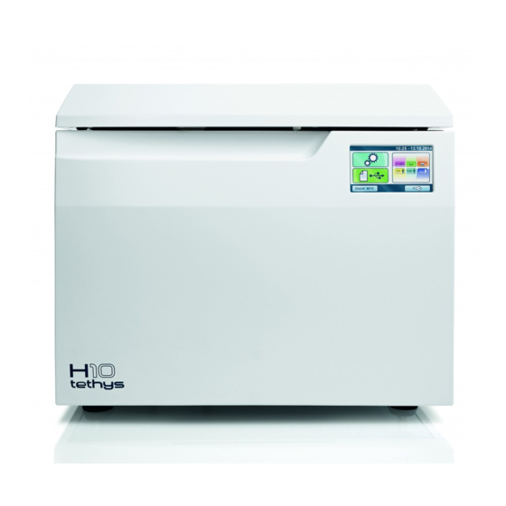
PRODUCT PRESENTATION Tethys H10 thermo-disinfector is the revolutionary proposal in the field of thermal disinfection, as well as the new point of reference in terms of safety, performance, efficiency and ease of use. It is a sophisticated but, at the same time, easy to use device that, thanks to its wide range of configuration options, meets any need of washing and disinfection of medical equipment, ensuring the maximum performance in any conditions. - Page 10 1. Door 2. Control panel and LCD screen 3. Power switch 1. Door locking system 2. Air inlet 3. Rotary nozzle 4. Detergent inlet 5. Decalcified water inlet 6. HEPA filter 7. Temperature probe input (process validation) 1. Stainless steel chamber 2.
-
Page 11: Lcd Icons
OF USE WILL BE DESCRIBED IN THE RELATIVE PARAGRAPHS. EXAMPLE OF WORKING CYCLE The disinfection programme of Tethys H10 series can be effectively described as a succession of phases, each one with a very precise purpose. Example of washing cycle with ultrasounds and disinfection: WASHING TIME means the period of time between the reaching of set washing temperature and drainage start. -
Page 12: Setting Up The Device
SETTING UP THE DEVICE FOREWORD The first and essential step for a proper and safe operation of the thermo-disinfector, its durability and complete use of its features is a correct installation, through the thorough compliance with these instructions. NOTE TECHNICAL SERVICE DEPARTMENT (SEE APPENDIX) IS AVAILABLE FOR ANY DOUBT OR FURTHER INFORMATION. -
Page 13: Foot Adjustment
FOOT ADJUSTMENT Thermo-disinfector Tethys H10 features four adjustable feet allowing to perfectly level it and compensate for any imperfection of the bearing surface. Feet can be adjusted by simply screwing or loosening them. POWER SUPPLY The electrical system to which the thermo-disinfector will be connected must be suitably dimensioned according to the electrical characteristics of the device. -
Page 14: Electrical Connections
ELECTRICAL CONNECTIONS The thermo-disinfector must be connected to a socket of the electric system having adequate capacity for the absorption of the device and properly earthed, in accordance with laws and/or regulations in force. The socket must be properly protected through magneto-thermal and differential circuit breakers having the following characteristics: 230-240V/50Hz 10 A... -
Page 15: Hydraulic Set-Up
HYDRAULIC SET-UP WATER FILLING WATER INLET CONNECTION The device is equipped with mains water filling pipe. Pipe is pre-set for tap connection, with integrated "Aquastop" system serving as a protection against any water leak, with 3/4" gas threaded connector. NOTE TO AVOID BACK-SIPHONAGE TO THE WATER MAINS, INSTALL A NON- RETURN DEVICE ACCORDING TO PREVAILING STANDARDS. -
Page 16: Mains Water
MAINS WATER For the operation of the machine it is necessary a connection to a 'drinkable' water mains providing water with maximum hardness of 54°f, and total dissolved iron content, Fe2+ and Fe3+, not exceeding 0.5 ppm. NOTE IF MAINS WATER CONTAINS A QUANTITY OF FE2+/FE3+ IRON EXCEEDING 0.5 PPM AND/OR MAINS WATER HARDNESS EXCEEDS 54°f (FRENCH DEGREES), A PRE-TREATMENT OF WATER MUST BE CARRIED OUT BY INSTALLING A DEFERRIZATION AND/OR SOFTENING... - Page 17 WARNING IT IS ADVISABLE TO CONNECT THE DRAINAGE PIPE TO A SIPHON WITH A MINIMUM HEIGHT OF 50 MM THAT CAN BE INSPECTED FROM THE LOWER PART. During installation operations please observe the following precautions: since the temperature of drainage water is 95°C, both drainage pipe ends must be fixed to the hose fitting and duly secured in place with the supplied clamp;...
-
Page 18: First Start-Up
FIRST START-UP To open the thermo-disinfector it is necessary to release the door applying moderate force and take it to the vertical position. DOOR OPENING WARNING TO PREVENT THE RISK OF FINGER CRUSHING TAKE THE DOOR TO ITS COMPLETE OPENING. OPERATOR'S MANUAL... -
Page 19: Basket Extraction And Insertion
BASKET EXTRACTION AND INSERTION Remove the basket by seizing it through the proper handles as shown in the figure. Once it is refitted inside the chamber, make sure that both handles are correctly positioned in the proper seats on the chamber surface. NOTE HANDLE WRONG POSITIONING MAY LEAD TO WATER LEAKAGE DURING CYCLES AND THE DEVICE COULD SHOW OPERATING... -
Page 20: Filling Of Salt Reservoir
FILLING OF SALT RESERVOIR The thermo-disinfector is equipped with an inner salt reservoir, used for regeneration of ion exchange resins contained in the integrated water softening system. At the first use after installation it is necessary to fill completely the reservoir with water, then with salt. -
Page 21: Filling Of Detergent Reservoir
FILLING OF DETERGENT RESERVOIR The thermo-disinfector is equipped with an inner reservoir for detergent to fill before the use. Remove the reservoir plug and insert the supplied funnel. Fill the supplied container and slowly pour the detergent. Visually check that the maximum reservoir filling level is not exceeded. At the end of the operation refit the detergent reservoir plug. -
Page 22: Door Closing
NOTE FOLLOW THE INSTRUCTIONS FOR USE OF THE DETERGENTS INDICATED IN THIS MANUAL. EFFECTIVENESS WASHING THERMAL DISINFECTION HAS BEEN TESTED IN ACCORDANCE WITH THE APPLICABLE STANDARDS USING THE VALIDATED WASHING AGENTS ACCORDING PRECISE PARAMETERS DURATION, TEMPERATURE, EXTENSION AND DOSAGE. THE USE OF DETERGENTS OTHER THAN THOSE VALIDATED BY THE MANUFACTURER OR A USE OTHER THAN THE INDICATED ONE CAN CAUSE MALFUNCTIONS AND/OR DAMAGE OF THE DEVICE AND OF THE TREATED MATERIALS. -
Page 23: Starting
STARTING WARNING DO NOT TURN ON THE THERMO-DISINFECTOR IF USB STICK IS INSERTED. MAIN MENU At the end of starting procedure the following main menu is displayed. The device waits for the cycle selection. WARNING THE FIRST TIME THE DEVICE IS USED AFTER THE INSTALLATION AND AFTER A PERIOD OF INACTIVITY EXCEEDING 24 HOURS IT IS NECESSARY TO CARRY OUT AN EMPTY 90°... -
Page 24: Configuration
CONFIGURATION The Tethys H10 series offers a wide range of customizable options. The user can thus configure the device according to his/her own needs, adapting the performance based on, for example, the type of activity carried out, the type of material to be washed and disinfected and the frequency of use. - Page 25 DATE AND TIME Use the cursors shown in the figure to adjust date and time. Press to confirm the selection. 1. time zone 2 hours 3 minutes 4 day 5 month 6 year USER The USER function allows limiting the use of the thermo-disinfector to a pre-defined number of users.
- Page 26 After ADMIN user registration, the following screen is displayed when accessing user management. Select the user from the list. NOTE IF ADMIN USER ENTERS THE PIN INCORRECTLY FOR 3 TIMES, IT IS NECESSARY TO USE THE UNLOCKING PROCEDURE DESCRIBED IN APPENDIX - ADMIN USER PIN RESET.
- Page 27 By pressing button, the data of the highlighted user are displayed: The ADMIN user can change the PIN of the user highlighted in the user list by inserting directly the new PIN or promoting him/her to ADMIN. By pressing button, the ADMIN user can delete the highlighted user from the list. Confirm the deletion by pressing OK or press button to go back.
- Page 28 Enter the PIN. The generic user can change his/her own PIN, by entering directly the new PIN, he/she can display the cycles he/she is enabled to perform and consult his/her data. For the generic user (not ADMIN) the list of cycles is in read mode only. OTHER CYCLES Press "Other Cycles"...
- Page 29 RESIN REGENERATION CYCLE With a frequency programmed based on set water hardness, device automatically regenerates resins during the following cycles: "Disinf. 90°C", "Washing", "D1 Custom", "D2 Custom" and "W1 Custom". In any case, the first time thermo-disinfector is used or after a period of inactivity exceeding 24 hours, it is recommended to manually run a "Resin Regeneration"...
- Page 30 ULTRASONIC TEST CYCLE To test ultrasound operation, refer to the technical standard "Australian Standard™ AS 2773.2-1999 Ultrasonic cleaners for health care facilities” PART 2 - SECTION 6 - Point 6.2 - method ii) both for test execution and result. Set the device as explained in the Standard and press the button shown in the Figure. NOTE USE ONE BASKET ONLY.
- Page 31 Insert tester in the centre of basket and close cover. NOTE BEFORE PRESSING "YES", MAKE SURE THAT TESTER HAS BEEN INSERTED IN THE CENTRE OF BASKET AND THAT COVER HAS BEEN CLOSED OPERATOR'S MANUAL...
- Page 32 NOTE INSERT THE TESTER WITHIN 20 MINUTES. At the end of the ULTRASOUND TEST the following screen appears and the device is ready to be used. OPERATOR'S MANUAL...
- Page 33 DECALCIFICATION CYCLE A white thin layer could deposit on cover and chamber metal surfaces due to a high setting of water hardness value. Machine can be cleaned running the special "Decalcification" cycle. When carrying out this cycle, use a special limescale remover for water fittings, to be filled in manually.
- Page 34 PREFERENCES Press "PREFERENCES" to set: Water hardness Unit of meas. Display WATER HARDNESS The device embeds a softening system allowing to reduce mains water hardness. When device is started for the first time, user will be prompted to set water hardness value in French degrees (°f).
- Page 35 The "resin regeneration" (ON/OFF) message signals whether resin regeneration management is active and depends on set hardness value. The table below compares the hardness values that can be set (in °f) with the regeneration frequency and the number of allowed cycles with salt reservoir at low level. The factory default value of the device is “21-30”...
- Page 36 UNITS OF MEASUREMENT Use the cursors shown in the figure to set temperature, water level conversion to 'inchH2O', time format (12 or 24 hours) and date. Press to confirm the selection. DISPLAY Use the cursors shown in the figure to set: the desired screen brightness screen saver activation time out (the current time is displayed).
- Page 37 SERVICE This menu is intended for the technical service department. OPERATOR'S MANUAL...
-
Page 38: Preparation Of The Material
PREPARATION OF THE MATERIAL First of all it should be noted that, when touching and handling contaminated material, it is advisable to take the following precautions: Wear a protective mask and goggles. Wear rubber gloves of adequate thickness; Clean your gloved hands with a germicide detergent; Always carry the instruments on a tray;... - Page 39 OPERATOR'S MANUAL...
-
Page 40: Cycles
CYCLES WARNING BEFORE EACH CYCLE CHECK THAT THE ROTARY NOZZLE TURNS AND THAT THERE ARE NO INTERFERENCES WITH THE LOAD INSIDE THE WASHING CHAMBER. IF THE ROTATION DOES NOT TAKE PLACE CORRECTLY AND FREELY, CARRY OUT THE NOZZLE MAINTENANCE (SEE MAINTENANCE APPENDIX). - Page 41 After having inserted the load in the thermo-disinfector basket (following the precautions indicated in 'Preparing the material' chapter) select the desired cycle by pressing the button: Start the cycle by pressing the button corresponding to THERMAL DISINFECTION. The cycle counter appears in the upper left corner. 1.
-
Page 42: Washing Cycle (W)
WASHING CYCLE (W) The washing process aims at eliminating organic and inorganic residues present on the instruments at the end of their use and is suitable for almost all materials, except for the porous, hygroscopic and water-soluble ones. Rotary instruments, instruments made of untreated aluminium or with decorative anodizing and instruments with ducts or cavities with reduced opening and high depth, are explicitly excluded from use. -
Page 43: Pre-Washing Cycle
Start the cycle by pressing the button corresponding to WASHING CYCLE. The cycle counter appears in the upper left corner. WARNING AT THE END OF THE CYCLE IT IS ESSENTIAL TO VISUALLY INSPECT THE OBJECTS TO CHECK THEIR PROPER WASHING. PRE-WASHING CYCLE The pre-washing cycle is advised to avoid the drying of organic residues on the instruments and facilitate their removal during the following washing or thermal disinfection cycle. - Page 44 Start the cycle by pressing the button corresponding to PRE-WASHING CYCLE. The cycle counter appears in the upper left corner. OPERATOR'S MANUAL...
-
Page 45: Custom Cycles
CUSTOM CYCLES In addition to preset programmes (90° DISINFECTION, WASHING and PRE-WASHING) that cannot be modified by the user, customizable programmes are available. D1 CUSTOM and D2 CUSTOM are DISINFECTION programmes that can be set according to the needs of the user. W CUSTOM is a WASHING programme that can be set according to the needs of the user. - Page 46 For cycle correct setting, set thermal disinfection temperature (80°C or 90°C), A0 value, washing duration and drying duration. A0 parameter can be set between 600 and 6000 with increments of 600, with thermal disinfection at 90°C. If thermal disinfection at 80°C is selected, A0 parameter can be set between 600 and 1200, in steps of 300.
-
Page 47: Washing Cycle Defined By The User (W1 Custom)
WASHING CYCLE DEFINED BY THE USER (W1 CUSTOM) In the washing cycle set by the customer it is possible to set the duration (time) of the washing cycle among the selectable options. WARNING THE LOAD TREATED WITH THIS PROGRAMME IS NOT DISINFECTED. USE THIS CYCLE ONLY AS A PREPARATION TO A SUBSEQUENT THERMAL DISINFECTION PROGRAMME OR IF THE LOAD TO TREAT CAN NOT BE TREATED AS A MINIMUM AT 80°C OR FOR MATERIALS... - Page 48 WARNING AT THE END OF THE CYCLE IT IS ESSENTIAL TO VISUALLY INSPECT THE OBJECTS TO CHECK THEIR PROPER WASHING. OPERATOR'S MANUAL...
-
Page 49: Drying Function
DRYING FUNCTION A function allowing to adjust the drying time of each cycle is available. NOTE "STANDARD" DRYING ALLOWS TO REMOVE WATER RESIDUES FROM A COMPLETE LOAD OF METAL INSTRUMENTS. TO OBTAIN BETTER DRYING PERFORMANCE, IT IS RECOMMENDED TO SET A LONGER TIME DEPENDING ON THE TYPE OF LOAD. After selecting the desired cycle, hold the following key pressed to set the drying time: Set total drying minutes of the process. -
Page 50: Delayed Start Function
DELAYED START FUNCTION A function to set cycle delayed start is available. After selecting the desired cycle, hold the following key pressed to set the delay time:" Set delayed start time. The minimum value that can be set is 30 minutes. Cycle start time is displayed close to command. -
Page 51: Execution Of The Cycle
EXECUTION OF THE CYCLE Take, for example, the execution of Thermal disinfection (D90) cycle, which includes the following phases: Pre-washing Washing 3 Rinses Heating Thermal disinfection (from thermal disinfection temperature reaching to drainage included). Drying: 1. Temperature in the chamber 2. -
Page 52: Door Opening At The End Of The Cycle
DOOR OPENING AT THE END OF THE CYCLE At the end of the cycle, in case of successful outcome, it is necessary to release the door locking mechanism by pressing the key shown in the figure, to allow door opening. WARNING AT THE END OF THE CYCLE IT IS ESSENTIAL TO VISUALLY INSPECT THE OBJECTS TO CHECK THEIR PROPER WASHING. -
Page 53: Data Management
DATA MANAGEMENT To access DATA MANAGEMENT section press the relevant icon. SYSTEM INFORMATION By selecting SYSTEM INFO all the information about the thermo-disinfector settings are displayed. DOWNL. CYCLE DATA It is possible to copy data about the cycles carried out, stored in the inner memory of the thermo-disinfector, on a USB stick. - Page 54 Before carrying out the following operations insert the USB stick. If the USB stick is not present, its insertion is required. It is possible to select the number of cycles to download on the external storage device. The available selections are "New", "Last 10", "Last 50", "Last 100" or "Custom Mode". If you choose the Customized option set the cycle interval you want to download.
- Page 55 ETHERNET The thermo-disinfector can be connected to an Ethernet local network through the proper connector placed on the rear of the machine. Using a web browser (such as Internet Explorer, Chrome, Firefox, etc.) from a PC or another device connected to the local network (tablet, smartphone, etc.) it is possible, by inserting the TCP-IP number assigned to the machine, to query the latter to check its operating state.
- Page 56 Display the Ethernet configuration page: Make sure that Automatic DHCP configuration is selected. With this selection all the numeric fields present on the screen are disabled (they get grey). With this setting at each start the machine requires the network DHCP server its own configuration using the DHCP protocol.
- Page 57 2) CONNECTION TO A LOCAL NETWORK EQUIPPED WITH DHCP SERVER, WITH THERMO-DISINFECTOR CONFIGURED WITH STATIC IP. In order to avoid checking often the TCP-IP number assigned dynamically from a DHCP Server, it is possible to assign manually a fixed number of the dynamic numbering of the local network.
- Page 58 3) DIRECT CONNECTION WITH CABLE BETWEEN THERMO-DISINFECTOR AND PC It is possible to connect a PC (e.g. a notebook) and a thermo-disinfector directly through a network cable, without having to connect them both to a local network. To obtain the connection, PC and thermo-disinfector have to be configured in static mode, as shown in the previous example, taking care that the two devices have the first three fields with the same numbering (e.g.
- Page 59 WIFI For WIFI configuration, follow the instructions given above for Ethernet network configuration. Select the option as shown below: OPERATOR'S MANUAL...
-
Page 60: Appendix - Technical Characteristics
APPENDIX - TECHNICAL CHARACTERISTICS SUMMARY TABLE THERMO-DISINFECTOR Device Tethys H10 Class (according to Directive 93/42/EEC and subsequent amendments) CEFLA s.c. Manufacturer Via Selice Prov.le 23/a 40026 Imola BO - Italy 220-240V 50 Hz Input voltage 220-240V 60 Hz 120 V 60 Hz F1: F15A 250V 6.3x32mm (mains power source) -
Page 61: Safety Devices
54 °f Hardness of mains water (max) NOTE: for values above 41° f, we recommend using an external softening system Fe2+ / Fe3+ (max) 0.5 ppm Inlet water temperature max 30 °C Limits according to water Minimum microbiological quality required: microbial contamination "drinkable type water"... -
Page 62: Summary Table Of Cycles
SUMMARY TABLE OF CYCLES DISINFECTION 0’ 6’ 7’ 3,000 4’ 36’ 6’ ÷ 25’ 0’ W WASHING 6’ 7’ 20’ 6’ ÷ 25’ PRE-WASHING 5’ 7’ DISINFECTION 600÷ 1,200 10’-20’ D1 CUSTOM (at 80 °C) (at 80 °C) 6’ ÷ 15’ 7’÷16’ 0’... - Page 63 WARNING THE DEVICE IS INTENDED EXCLUSIVELY FOR WASHING AND/OR THERMAL DISINFECTION OF REUSABLE SURGICAL INSTRUMENTS ABLE TO WITHSTAND A TEMPERATURE OF AT LEAST 80 °C OR 90°C, BASED ON SELECTED CYCLE. INTENDED WASHING THERMAL DISINFECTION OF THERMOLABILE MEDICAL DEVICES. IT IS NOT INTENDED FOR THE WASHING OF INSTRUMENTS HAVING DEEP CAVITIES WITH REDUCED OPENING (SINCE CLEANING AND DISINFECTION OF THE INNER PARTS OF CAVITIES ARE NOT ENSURED).
-
Page 64: Programmes Scheme
PROGRAMMES SCHEME DISINFECTION WASHING TIME means the period of time between the reaching of set washing temperature and drainage start. WASHING WASHING TIME means the period of time between the reaching of set washing temperature and drainage start. PRE-WASHING OPERATOR'S MANUAL... -
Page 65: Appendix - Maintenance
APPENDIX - MAINTENANCE In addition to correct use, the user needs to perform ordinary maintenance in order to guarantee safe, efficient operation over the device’s entire life. FOREWORD For better quality of maintenance, supplement routine checks with regular periodic check-ups see Appendix that can be performed by Technical Service Department ( It is also fundamental to perform a periodic thermo-disinfector validation, i.e. -
Page 66: Scheduled Maintenance Messages
SCHEDULED MAINTENANCE MESSAGES The thermo-disinfector periodically displays warning messages relevant to 'routine' maintenance operations that must be carried out in order to ensure the proper operation of the device. Press DONE to confirm that the envisaged maintenance operation has been performed. -
Page 67: Description Of Maintenance Interventions
DESCRIPTION OF MAINTENANCE INTERVENTIONS Let’s now look at the various operations to be carried out. CLEAN THE GASKET To eliminate any traces of limestone or dirt, clean the gasket with a cotton cloth soaked in a soft solution of water and vinegar (or a similar product, checking the contents on the label before using). -
Page 68: Clean Chamber Filters
CLEAN CHAMBER FILTERS Remove the basket from the washing chamber. Remove the filters (1) and (2) on the bottom of the chamber ensuring that possible residues do not drop inside the hole. Rinse thoroughly the parts that compose filters (1) and (2) under running water and reposition them in their housings. -
Page 69: Hepa Filter Replacement
HEPA FILTER REPLACEMENT To remove HEPA filter, unscrew the 4 screws using the supplied Allen wrench. Disassemble the grid and replace the filter with a new one, then reassemble the grid. NOTE REQUEST HEPA FILTER DIRECTLY FROM THE TECHNICAL SERVICE DEPARTMENT OF THE DEALER OR RESELLER THAT SUPPLIED THE PRODUCT. -
Page 70: Periodic Thermo-Disinfector Validation
PERIODIC THERMO- DISINFECTOR VALIDATION The reference Standard for a thermo-disinfector performance is UNI EN ISO 15883. Referring to par. 6 of EN ISO 15883-1, in addition to the conformity to the device 'as supplied', borne by the manufacturer, the regulations require further checks on the device 'as installed' through a process called 'validation'. -
Page 71: Device Useful Life
DEVICE USEFUL LIFE Ultrasound thermo-disinfector service life is of 10 years (average use: 5 cycles/day, for 220 days/year), in compliance with the routine maintenance prescriptions set forth in the use and maintenance manual. This lapse of time, which is obviously not linked to an intrinsic "expiry date" of the product, is established based on the data inferred by the following evaluations: - Average replacement ratio of the device by the user (turn-over);... -
Page 72: Appendix - General Problems
APPENDIX - GENERAL PROBLEMS FOREWORD If while using the device a problem or an alarm occurs, this DOES NOT mean that the device is out of order. It may not, in fact, be related to a breakdown but, more probably to an anomalous situation, often merely transitory (such as a blackout), or incorrect use. -
Page 73: Troubleshooting
TROUBLESHOOTING If your thermo-disinfector is not working correctly, please make the following checks before contacting the Technical Service Department: TROUBLE POSSIBLE CAUSE PROPOSED SOLUTION The power cord is not Plug it in. plugged-in. There is no voltage at the Check the cause of the lack of voltage at socket. -
Page 74: Appendix - Alarms
APPENDIX – ALARMS NOTE IF THE PROBLEM PERSISTS, ADDRESS TO TECHNICAL SERVICE DEPARTMENT (SEE APPENDIX) COMMUNICATING THE MODEL AND SERIAL NUMBER OF THE THERMO-DISINFECTOR. THESE DATA ARE INDICATED IN THE REGISTRATION PLATE, ON THE REAR PART OF THE DEVICE. FOREWORD Every time an anomalous condition occurs during the operation of the thermo-disinfector, an alarm is generated, identified by a specific code (consisting of a letter followed by a 3-digit number). -
Page 75: System Reset
SYSTEM RESET The system can be reset in two alternative ways, depending on the type of alarm occurred (see the List of alarm codes below in this appendix): a) Pressing the OK button. b) Following the instructions displayed and holding down the RESET button for about 3 seconds: Error Code Error Description... -
Page 76: Troubleshooting
TROUBLESHOOTING ALARM CODES The list of alarm codes, the relevant messages displayed and RESET modes, are indicated in the following table: ERRORS (CATEGORY A) CODE MESSAGE DESCRIPTION EXIT DISPLAY Micro-switch state inconsistent with 3 (in cycle) A025 DOOR LOCK PROBLEM door state 2 (stand-by) RESIN REGENERATION... - Page 77 CODE MESSAGE DESCRIPTION EXIT DISPLAY US UPDATE A957 Ultrasound board update error 2 (stand-by) TRANSMISSION ERROR Incorrect US board power supply A958 US VOLTAGE PROBLEM voltage 1 = OK (warning) + chamber emptying 2 = OK (warning) 3 = cycle interruption + ok + door unlock + reset 3 OPERATOR'S MANUAL...
- Page 78 ERRORS (CATEGORY E) CODE MESSAGE DESCRIPTION EXIT DISPLAY E000 BLACKOUT Black-Out. E001 OVERVOLTAGE Overvoltage. NETWORK FREQUENCY E004 Network frequency reading problem ERROR E011 LID OPEN! Attempt to start a cycle with lid open. Attempt to start a cycle with chamber E552 WAIT! drainage in progress after full chamber...
- Page 79 ERRORS (CATEGORY H) CODE MESSAGE DESCRIPTION EXIT DISPLAY Error in time information (align with H410 TIMER ERROR autoclave). Difference of temperature over the limit H560 DELTA PT1-PT2 ERROR between Pt1 (regulation probe) and Pt2 (control probe) during washing phase TEMPERATURE ABOVE Temperature PT1 over the limit H561 MAX LIMIT...
- Page 80 ERRORS (CATEGORY S) CODE MESSAGE DESCRIPTION EXIT DISPLAY S001 FLASH NOT ACCESSIBLE Flash memory not accessible S002 FLASH FULL Flash memory full. SD CARD NOT Micro SD card not accessible for data S003 ACCESSIBLE storage in start-up phase. S004 SD CARD FULL Micro SD Card full USB stick not accessible (interruption S005...
- Page 81 TROUBLESHOOTING According to the type of alarm occurred, please find below the indications to detect the possible causes and restore the proper operation: ERRORS (CATEGORY A) CODE POSSIBLE CAUSE SOLUTION Contact Technical Service Department. Failure to the micro-switch or to the door If the instruments need to be removed, it locking system magneto.
- Page 82 ERRORS (CATEGORY A) CODE POSSIBLE CAUSE SOLUTION Check that filling water tap is open. Check pressure and flow of mains water. Mains water pressure or flow insufficient. If too low (see technical data table), Partial clogging of internal water circuit. check filter condition in connection union Partial clogging of SV2.
- Page 83 ERRORS (CATEGORY A) CODE POSSIBLE CAUSE SOLUTION Power supply voltage: Contact your trustworthy plumber to <100Vac; check the system. A958 ranging between 150Vac and 180Vac; If the problem persists, contact Technical > 270Vac. Service Department. ERRORS (CATEGORY E) CODE POSSIBLE CAUSE SOLUTION Check the continuous presence of power supply.
- Page 84 ERRORS (CATEGORY H) CODE POSSIBLE CAUSE SOLUTION If the problem persists, contact Technical H410 Malfunction of electronic control board. Service Department. Malfunction in temperature detection If the problem persists, contact Technical H560 during washing. Service Department. If the problem persists, contact Technical H561 Too high temperature during washing.
- Page 85 ERRORS (CATEGORY S) CODE POSSIBLE CAUSE SOLUTION If the problem persists, contact S001 Failure to control board. Technical Service Department. If the problem persists, contact S002 Failure to control board. Technical Service Department. If the problem persists, contact S003 Failure to control board. Technical Service Department.
-
Page 86: Appendix - Admin User Pin Reset
In this regard, please refer to the following address: Manufactured by CEFLA s.c. Sede Legale ed Amministrativa / Head Quarter Via Selice Provinciale, 23/a – 40026 Imola (BO) Italy Stabilimento / Plant Via Bicocca, 14/c – 40026 Imola (BO) Italy http://www.anthos.it http://www.sternweber.it http://www.castellini.it http://www.mocom.it OPERATOR'S MANUAL...
Need help?
Do you have a question about the Tethys H10 and is the answer not in the manual?
Questions and answers