
Related Manuals for Mocom millenium B2


Summary of Contents for Mocom millenium B2
- Page 1 ® STEAM STERILIZER ® ® Quality System certified by OPERATING MANUAL Rev. Date: January 2008...
-
Page 2: Table Of Contents
TABLE OF CONTENTS REVISIONS The following table lists subsequent editions/revisions of the manual. The “Description” field brief explains the subject of the latest revision. Rev. Date Description 11-02 First issue 02-03 A few modifications; added new chapter “Replacing the printer paper” 03-04 A few small modifications;... - Page 3 TABLE OF CONTENTS 5 - FIRST START-UP........................15 TURNING ON THE EQUIPMENT ........................15 INITIAL AUTOMATIC TEST..........................15 ACQUISITION AND UPDATING OF THE AMBIENT PRESSURE VALUES ............15 STAND-BY MODE ............................16 FILLING DISTILLED WATER ...........................17 Manual filling.............................17 Automatic filling ............................17 MAX LEVEL IN THE INTERNAL/EXTERNAL DRAIN TANK ................18 6 - CONFIGURATION........................
- Page 4 TABLE OF CONTENTS SAFETY DEVICES............................54 WATER SUPPLY CHARACTERISTICS......................55 APPENDIX B – PROGRAMS ......................56 INTRODUCTION .............................. 56 PROGRAM SUMMARY TABLE ........................57 STERILIZATION PROGRAM DIAGRAM......................59 DIAGRAMS OF THE TEST PROGRAMMES ....................64 EXAMPLES OF PRINTED REPORTS ......................65 APPENDIX C –...
-
Page 6: Introduction
1. INTRODUCTION Dear Customer INTRODUCTION Thank you for choosing a product from M.O.COM. Srl. We hope that you will find it completely satisfactory. This manual describes all procedures for the correct use of the device and instructions for deriving the full benefit from its features. In any case, we will be available to provide explanations and to receive any suggestions you may have for improving our products or services. -
Page 7: Purpose Of The Manual
1. INTRODUCTION The purpose of this manual is to provide instructions for: PURPOSE OF THE MANUAL – becoming generally familiar with the product; – its correct installation and configuration; – its safe, efficient use; – handling materials before and after sterilization. Its appendices also provide: –... -
Page 8: Contents Of The Package
2. CONTENTS OF THE PACKAGE Total weight about 75 kg CONTENTS OF THE PACKAGE NOTE DIMENSIONS HECK THE INTEGRITY OF THE PACKAGE UPON AND WEIGHT RECEIPT Once the package is opened, check that: – the supply matches the specifications of the order (see the accompanying document);... -
Page 9: Handling The Product
2. CONTENTS OF THE PACKAGE Where possible, the packaged product must be handled using suitable mechanical means HANDLING THE (forklift truck, transpallet, etc.) and following the instructions shown on the package. PRODUCT In the case of manual handling, the product must be lifted by two persons using the handles cut in the side of the box. -
Page 10: Product Introduction
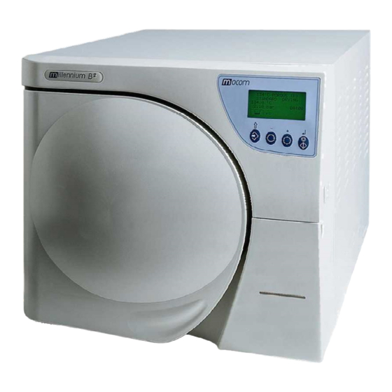
3. PRODUCT INTRODUCTION Millennium B² is MO.COM.'s revolutionary type B (EN 13060) small steam sterilizer and a PRODUCT new de facto standard for safety, performance, flexibility and ease of use. INTRODUCTION It is a sophisticated but, at the same time, easy to use device that, thanks to its wide range of INTRODUCTION configuration options and patented operating devices, satisfies every need for sterilizing medical devices, guaranteeing the maximum performance under all conditions. -
Page 11: Front
3. PRODUCT INTRODUCTION FRONT LCD display and control panel Door On/Off switch Service compartment access panel Printer paper output slot Sterilization chamber Door microswitch Motorized closing system Bacteriological filter RS232 serial port Millflash interface Built-in printer Service compartment open Used water drain quick connector Distilled water fill quick connector Water drain plug and filter Door... -
Page 12: Rear
3. PRODUCT INTRODUCTION Jack for Milldrop REAR Start/Stop cable Distilled water tank vent hole Safety valve Heat exchanger Distilled water tank draining point (maintenance) Jack socket for the external tank level sensor (option) Connection for automatically filling the distilled water tank Connection for directly draining the used water tank Band heating element safety thermostat and manual... -
Page 13: Control Panel
3. PRODUCT INTRODUCTION CONTROL PANEL Liquid Crystal Display (LCD) Command keys The function of the command keys differ according to operating mode of the equipment. NORMAL mode SETUP mode Enter, confirmation of the value/option Cycle Start/Stop selected Value increment / Forward scroll of Sterilization cycle selection the menu options Value decrement / Backward scroll of... -
Page 14: Operating Cycle Example
3. PRODUCT INTRODUCTION The Millennium B² sterilization program can be described as a succession of phases, each OPERATING with a specific purpose. CYCLE EXAMPLE For example, after loading the material in the chamber, closing the door, selecting the program and starting the cycle (and the consequent locking of the door opening mechanism), the standard program (for porous materials, 134 °C - 4’) offers the following sequence (see chart, below): 1. -
Page 15: Installation
4. INSTALLATION The first and fundamental step in achieving good sterilizer operation, long life and complete INSTALLATION use of its features is a correct, careful installation. Moreover, this precaution will avoid the danger of physical injury or property damage, not to mention malfunctions and damage to the INTRODUCTION machine. -
Page 16: General Installation Precautions
4. INSTALLATION Obey the following warnings for the correct operation of the device and/or to avoid risky GENERAL situations: INSTALLATION PRECAUTIONS Install the sterilizer on a flat surface; if necessary, adjust the leveling feet to compensate for an irregular surface and to slightly tilt lower the front part of the sterilizer. Make sure that the support surface is strong enough to support the device's weight (about 65 kg);... -
Page 17: Connecting An External Water Filling Tank
4. INSTALLATION To avoid having to periodically fill the water tank (see Chapter 5, “First Start-Up”), it is CONNECTING AN possible to connect the sterilizer to an external filling tank (supplied as an option), that the user EXTERNAL will periodically fill, or to a commercially-available, reverse-osmosis water purification system WATER FILLING with accumulation tank. -
Page 18: Connecting An External Drain Tank
4. INSTALLATION An external drain tank (supplied as an option) can be used to avoid having to periodically CONNECTING AN empty the internal used water tank, which is then manually emptied or connected to central EXTERNAL DRAIN drain system. TANK OPTIONAL, external NOTE drain function) -
Page 19: Direct Connection To Acentralized Draining Point
4. INSTALLATION – Connect the other end of the tube to the centralized draining point, checking the seal. NOTE AKE SURE THE TUBE IS NOT BENT CRUSHED OR OBSTRUCTED IN ANY WAY The following diagram provides an indicative arrangement of the components: Connection point of the centralized draining plant Sterilizer... -
Page 20: First Start-Up
5. FIRST START-UP Once the sterilizer has been correctly installed, it may be turned on and prepared for use. FIRST START-UP Turn on the equipment by the main (luminous) switch located on the right side of the machine. TURNING ON THE NOTE EQUIPMENT O THIS WITH THE STERILIZER... -
Page 21: Stand-By Mode
5. FIRST START-UP After the initial test, the sterilizer goes to STAND-BY mode and the display shows: STAND-BY MODE C o u n t e r x x x x x / y y y y y S t a n d - b y H I G H 2 3 . -
Page 22: Filling Distilled Water
5. FIRST START-UP The first time the sterilizer is used, and later when the MIN water level indicator comes on, you FILLING DISTILLED will have to fill, or top-off, the internal distilled water tank. WATER With reference to the figure (and with the door open), proceed as follows: Manual filling 1. -
Page 23: Max Level In The Internal/External Drain Tank
5. FIRST START-UP When the water level in the internal or external drain tank reaches the MAX level, the LCD MAX LEVEL IN THE display alternatively lights the MAX and MIN icons. INTERNAL/ EXTERNAL DRAIN TANK NOTE N THIS CONDITION THE UNIT WILL GENERATE AN ALARM INDICATION PPENDIX LARM AS YOU ATTEMPT TO LAUNCH A STERILIZATION CYCLE... -
Page 24: Configuration
6. CONFIGURATION Millennium B² offers personalization options never previously seen on any steam sterilizer. CONFIGURATION Users may configure the device to meet their own needs. For example, the device's performance may be adapted on the basis of the type of activity, the type of material to be sterilized or its frequency of use. - Page 25 ⇑ to exit EXIT WARNING! ADJUSTMENT OF THE LCD CONTRAST ONLY AVAILABLE FOR SERVICE OPEN THE DOOR +/- to set MOCOM SERVICE ⇑ TO CONTINUE to exit Firmware release REVIEW 1st PRESET to scroll to scroll to scroll Filling option...
-
Page 26: Description Of The Menu Items
CONFIGURATION DESCRIPTION OF Now, we describe the meaning of the various main menu and second-level menu items. THE MENU ITEMS MAIN MENU The main menu has 6 entries that open additional (second-level) menus: BASIC (basic options) ADVANCED (advanced options) SPECIAL (special options) SERVICE (menu not accessible to users) - Page 27 6. CONFIGURATION M I L L E N N I U M D A T E E x x x x / B G y y y y y y d d / m m / y y y y L A N G U A G E T I M E E N G L I S H...
-
Page 28: Defaults Settings
CONFIGURATION The sterilizer leaves the factory with the following settings: DEFAULTS SETTINGS DATE: current date TIME: current time PROGRAMS: Preset 1: 134°C POROUS (standard drying) Preset 2: 134°C HOLLOW (standard drying) Preset 3: 134°C SOLID (standard drying) Preset 4: 134°C EMERGENCY NOTE HE PROGRAMS INDICATED SHOULD BE CONSIDERED AS PREFERENTIAL SETTINGS OWEVER... -
Page 29: Setting The Time
6. CONFIGURATION When TIME SETTING is selected with the ↵ key, you will see: Setting the time (TIME SETTING on the BASIC menu) h h : m m : s s + / - s e t e n t e r ↵... -
Page 30: Setting The Sterilization Programs
CONFIGURATION Confirm with the ↵ key. NOTE DISABLE O CHANGE THE PASSWORD FIRST SELECT THE OPTION WHICH CANCELS ANY POWER-ON THE PREVIOUS PASSWORD AND THEN SELECT THE CYCLE START OPTION ENTERING THE NEW PASSWORD AS DESCRIBED ABOVE Setting the sterilization The program setting and their storing in four pre-set positions is achieved in various steps programs using several menus in sequence. - Page 31 6. CONFIGURATION As a function of the choices made, you will go to one of two alternative menus that allow selecting the type of drying to associate to the selected program. a) Programs with short drying (HOLLOW, SOLID, EMERGENCY): → S T A N D A R D D R Y I N G F A S T...
- Page 32 CONFIGURATION To define the CUSTOM program to associate to one of the pre-set position (1, 2, 3 or 4) proceed as follows: 1. Select PROGRAMS, select the program number to which the program is to be associated (see the previous description) and then select CUSTOM in the next screen; the following menu appears: →...
- Page 33 6. CONFIGURATION 5. Depending on the selection (SHORT or LONG) one of two different menus will open (these menus are the same for the standard cycles), i.e.: In SHORT mode the following is displayed: → S T A N D A R D D R Y I N G F A S T D R Y I N G...
-
Page 34: Setting The Stand-By Mode
CONFIGURATION Setting the STAND-BY Based on the equipment's frequency of use, or other considerations, it is possible to select the mode heating level during the STAND-BY (preheating) phase and the time beyond which STAND-BY (STAND-BY OPTIONS on is deactivated. When you select STAND-BY OPTIONS with the ↵ key, you access the following menu: the ADVANCED menu) →... -
Page 35: Setting The Printing Mode
6. CONFIGURATION Setting the printing The sterilizer is equipped with a printer for recording sterilization program data; it is necessary mode to set the parameters required for its proper operation. (PRINT OPTIONS on the 1. Select PRINT OPTIONS using the ↵ key and the following menu appears: ADVANCED menu) →... - Page 36 CONFIGURATION Item REPORT The following screen appears: → P R I N T O U T M O D E N R . C O P I E S ↑ P R I N T L A S T ↓ E X I T Select item PRINTOUT MODE to chose the mode the data are printed: The following options appear:...
-
Page 37: Setting The Tank Filling Mode
6. CONFIGURATION NOTE MANUAL F THE LAST CYCLE COMPLETED CORRECTLY OR WAS INTERRUPTED BY STOP) NORMAL EXTENDED IT WILL BE POSSIBLE TO REPRINT IT IN EITHER (MANUAL STOP MODE F THE LAST CYCLE WAS INTERRUPTED BY AN ALARM EXTENDED EXCLUDED IT ONLY THE MODE WILL BE AVAILABLE Following the reprint command, this message will be displayed:... -
Page 38: Acquisition Of The Ambient Pressure
CONFIGURATION When INTERNAL DRAIN is enabled, the reading of the MAX level sensor in the internal tank is enabled. The EXTERNAL DRAIN command also activates the MAX level sensor located in the external tank. NOTE HE LEVEL SENSOR IN THE INTERNAL TANK REMAINS ACTIVE IN ANY CASE TO PREVENT A POSSIBLE MALFUNCTION OF THE EXTERNAL TANK OR A MISSING OR FAULTY CONNECTION OF THE OPTIONAL EXTERNAL DRAIN TANK... -
Page 39: Adjusting The Contrast Of The Liquid Crystal Display
6. CONFIGURATION Adjusting the The LCD contrast adjustment allow to obtain the screen reading as clear as possible, contrast of the liquid compensating different sterilizer positioning or ambient brightness. crystal display (LCD CONTRAST on the When LCD CONTRAST is activated, this screen appears: SPECIAL menu) A D J U S T M E N T T H E... -
Page 40: Preparing The Material
7. PREPARING THE MATERIAL The sterilization process can be considered effective, reliable and repeatable so long as the PREPARING THE material is suitably treated first and then correctly arranged in the sterilization chamber in an MATERIAL orderly manner. INTRODUCTION In fact, it should be emphasized that organic residues or deposits of substances used in medical practice are the inevitable receptacles of microorganisms and may obstruct contact between the steam and the walls of the instrument, deactivating, at least locally, the lethal process that sterilization normally provides. -
Page 41: Arranging The Load
7. PREPARING THE MATERIAL For handles (turbines, contra-angles, etc.), supplement the above with treatment in suitable dedicated devices that provide effective internal cleaning (occasionally including lubrication). NOTE HE END OF THE STERILIZATION PROGRAM REMEMBER TO LUBRICATE THE INTERNAL HANDLE MECHANISMS USING SPECIAL STERILE... - Page 42 7. PREPARING THE MATERIAL Notes for rubber and plastic tubing – Always rinse before use with pyrogen-free water; do not dry them; – Arrange the tubing on the tray so that their ends are not obstructed or crushed. – Do not bend or wind them, but allow them to lie as straight as possible. Notes for packets and packages –...
-
Page 43: Program Selection
8. PROGRAM SELECTION Program selection is fundamental for a successful sterilization process. PROGRAM SELECTION Since each instrument, or material in general, has different shape, consistency and properties, it is important to identify the most suitable program for it, both for preserving its physical INTRODUCTION characteristics (avoiding or, at any rate, limiting alterations) as well to guarantee the most effective sterilization. - Page 44 8. PROGRAM SELECTION NOTE F NO STERILIZATION PROGRAM IS SELECTED THE EQUIPMENT CANNOT START A STERILIZATION CYCLE AND THE FOLLOWING MESSAGE APPEARS ON THE DISPLAY WITH A BEEP S E L E C T P R O G R A M P L E A S E .
-
Page 45: Running The Cycle
9. RUNNING THE PROGRAM A sterilization cycle consists of a determined number of phases. The number and duration of RUNNING the phases can differ for the programs, based on the type of air extraction, sterilization process THE CYCLE and drying method. INTRODUCTION The electronic control system monitors the various phases, at the same time checking that the various parameters are respected;... -
Page 46: Program Execution
9. RUNNING THE PROGRAM In case of the memory full or insufficient to store the new cycle data, the following message will be displayed: W A R N I N G C A R D F U L L ↵ c o n t i n u e e x i t W A R N I N G... - Page 47 9. RUNNING THE PROGRAM First vacuum phase When the optimum temperature is reached, the first vacuum phase (1st VACUUM PULSE) is started and brings the chamber pressure down to the established value. The display shows: 1 3 4 ° C P O R O U S V A C U U M P U L S E...
- Page 48 9. RUNNING THE PROGRAM Third rise in After the last vacuum phase, the pressure in the sterilization chamber must rise to the value pressure set for the sterilization process (3rd PRESSURE PULSE), always through the injection of steam. 1 3 4 ° C P O R O U S P R E S S U R E P U L S E...
- Page 49 9. RUNNING THE PROGRAM Drying After the steam under pressure is released, its forced removal begins with the vacuum pump (DRYING): for this purpose, low pressure is created in the sterilization chamber to facilitate the evaporation of the steam and its consequent elimination. As a function of the type of drying set, one of the following screens will appear: 1 3 4 °...
-
Page 50: Result Of The Cycle
9. RUNNING THE PROGRAM NOTE T THE END OF THE CYCLE AND UP TO THE OPENING OF THE DOOR THE HEATING ELEMENTS ARE OFF S A CONSEQUENCE THE DEVICE IS SLOWLY COOLING STAND-BY REGARDLESS OF WHAT THE MODE IS NOTE HENEVER THE STERILIZER DOOR IS NOT OPENED AT THE END OF THE CYCLE VACUUM PUMP IS PERIODICALLY ACTIVATED TO REMOVE ANY TRACES OF CONDENSATE... -
Page 51: Check Of The Cycle Data Report
9. RUNNING THE PROGRAM However, it is a good practice to check that the print report issued at the end of the sterilization CHECK OF THE program, also specifies a positive outcome. CYCLE DATA At the end of the cycle, the salient data for the thermodynamic parameters of the sterilization, REPORT temperature and pressure (°C and bar), and time (minutes) of the sterilization cycle, with particular attention to the sterilization phase true and proper, is printed by simply opening the... - Page 52 9. RUNNING THE PROGRAM Finally, when the door is opened, you will be asked to reset the device by the following message: M A N U A L S T O P R E S E T S Y S T E M 8 5 .
-
Page 53: Storing Sterilized Materials
10. STORING STERILIZED MATERIALS The sterilized material must be adequately treated and stored to maintain its sterility over time, STORING until its use. STERILIZED MATERIALS Inadequate storage can cause rapid recontamination. This leads to problems regardless of what you do since you will either be using INTRODUCTION recontaminated material (most of the time unconsciously), placing the user and patient at risk, or you will have to run the sterilization cycle again, with an inevitable waste of time and... -
Page 54: Test Programs
11. TEST PROGRAMS To protect the safety of users and patients, a fundamental process like sterilizing medical TEST PROGRAMS devices should be periodically checked. INTRODUCTION In this regard, Millennium B² offers the possibility of, simply and automatically, executing two distinct test programs: •... -
Page 55: Vacuum Test
11. TEST PROGRAMS The cycle phases are analogous to what is described in the Chapter, “Running a Sterilization Program”. At the end of the program, remove the test device, open the capsule and remove the indicator from its housing. If the steam has correctly penetrated, the ink will have completely changed color from what it was before, along the entire length of the strip;... - Page 56 11. TEST PROGRAMS Close the door and start the program with the START key. NOTE ANY CYCLE START F A PASSWORD HAS BEEN SET WITH THE OPTION SEE THE HAPTER ONFIGURATION ETTING THE PASSWORD YOU WILL BE ASKED TO ENTER THE ACCESS CODE N ADDITION THE EQUIPMENT CHECKS THE PRINTER PAPER PRESENCE AND...
- Page 57 11. TEST PROGRAMS When the program finishes, the display will read: V A C U U M T E S T T E S T P A S S E D - 0 . 0 1 b a r 1 7 : 4 4 The end of the program is signaled with a beep.
-
Page 58: Appendix A - Technical Characteristics
APPENDIX A – TECHNICAL CHARACTERISTICS APPENDIX A – TECHNICAL CHARACTERISTICS SUMMARY TABLE Device Steam Sterilizer Classification (as per 93/42 CEE) Model M.O.COM. S.r.l. Manufacturer Via delle Azalee, 1 20090 BUCCINASCO (MI) - ITALY Power supply voltage 220V – 240 V~ Frequency 50/60 Hz Mains fuses... -
Page 59: Safety Devices
APPENDIX A – TECHNICAL CHARACTERISTICS SAFETY DEVICES The sterilizer is equipped with the following safety devices for which we provide a brief description of their function: – Mains fuses (see summary table data) Protection inside the device against a fault in the heating elements. Action: cuts the electricity. -
Page 60: Water Supply Characteristics
APPENDIX A – TECHNICAL CHARACTERISTICS WATER SUPPLY CHARACTERISTICS DESCRIPTION WATER SUPPLY VALUES VALUES IN CONDENSATE DRY RESIDUE < 10 mg/l < 1 mg/l SILICON OXIDE SiO < 0.1 mg/l < 1 mg/l IRON < 0.2 mg/l < 0.1 mg/l CADMIUM <... -
Page 61: Appendix B - Programs
APPENDIX B – PROGRAMS APPENDIX B – PROGRAMS INTRODUCTION The steam sterilizer is appropriate for almost all materials and instruments, so long as they are able to tolerate, without damage, a minimum temperature of 121 °C (otherwise, you will need to use other low-temperature sterilization systems). The following material can normally be sterilized with steam: –... -
Page 62: Program Summary Table
APPENDIX B – PROGRAMS PROGRAM SUMMARY TABLE BASIC PROGRAM NOMINAL VALUES STERILIZABLE MATERIAL PARAMETERS PROGRAM DESCRIPTION NOTES TYPE Porous, unpackaged 1,25 0,40 0.30 material Porous material in 1,00 0,30 0.25 single package Porous material in 0,75 0,25 0.20 double package 134 °C POROUS 2,10 40÷44... - Page 63 APPENDIX B – PROGRAMS NOTES RACTIONATED VACUUM WITH THREE VACUUM PULSES SEE FIGURES IN THE FOLLOWING PAGES INGLE VACUUM WITH SINGLE VACUUM PULSE SEE FIGURES IN THE FOLLOWING PAGES = 10 POROUS WRAPPED MINUTES VACUUM DRYING TYPICAL OF CYCLES HOLLOW SOLID HORT MINUTES VACUUM DRYING...
-
Page 64: Sterilization Program Diagram
APPENDIX B – PROGRAMS STERILIZATION PROGRAM DIAGRAM Pressure (bar) PROGRAM 134c POROUS PROCESS 134°C - 4' 00'' 2.10 PROGRAM 2.00 134c PRION 134°C - 18' 00'' 1.00 Time (min) 0.00 -0.80 PRE-VACUUM LONG DRYING Pressure (bar) PROGRAM 121c POROUS 121°c - 20'00'' PROCESS 1.10 1.00... - Page 65 APPENDIX B – PROGRAMS Pressure (bar) PROGRAM 134c HOLLOW 134°C - 4'00'' PROCESS 2.10 2.00 1.00 Time (min) 0.00 -0.80 -1.00 FRACTIONATED PRE-VACUUM SHORT DRYING Pressure (bar) PROGRAM 121c HOLLOW 121°c - 20'00'' PROCESS 1.10 1.00 Time (min) 0.00 -1.00 SHORT DRYING PRE-VACUUM...
- Page 66 APPENDIX B – PROGRAMS Pressure (bar) PROGRAM 134c WRAPPED PROCESS 134°C - 4'00'' 2.10 2.00 1.00 Time (min) 0.00 -1.00 ONE SHOT PRE-VACUUM LONG DRYING Pressure (bar) PROGRAM 121c WRAPPED 121°C - 20'00'' PROCESS 1.10 1.00 Time (min) 0.00 -1.00 ONE SHOT PRE-VACUUM LONG DRYING...
- Page 67 APPENDIX B – PROGRAMS PROGRAM Pressure (bar) 134c SOLID 134°C - 4'00'' PROCESS 2.10 2.00 1.00 Time (min) 0.00 -1.00 ONE SHOT PRE-VACUUM SHORT DRYING PROGRAM Pressure (bar) 121c SOLID 121°C - 20'00'' PROCESS 1.10 1.00 Time (min) 0.00 -1.00 ONE SHOT PRE-VACUUM SHORT DRYING...
- Page 68 APPENDIX B – PROGRAMS Pressure (bar) PROGRAM 134c EMERGENCY 134°C - 3'00'' PROCESS 2.10 2.00 1.00 Time (min) 0.00 -1.00 ONE SHOT PRE-VACUUM DRYING PROGRAM Pressure (bar) XXXc CUSTOM 134°C - from 4'00'' to 30'00'' 121°C - from 20'00'' to 30'00’’ 2.10 2.00 SETUP...
-
Page 69: Diagrams Of The Test Programmes
APPENDIX B – PROGRAMS DIAGRAMS OF THE TEST PROGRAMMES Pressure (bar) PROGRAM BOWIE & DICK TEST 134°C - 3'00'' PROCESS 2.10 2.00 1.00 Time (min) 0.00 -1.00 FRACTIONATED PRE-VACUUM SHORT DRYING PROGRAM Pressure (bar) VACUUM TEST (VT) -0.80 bar 1.00 Intermediate condition for End condition for the continuation of the test... -
Page 70: Examples Of Printed Reports
APPENDIX B – PROGRAMS EXAMPLES OF PRINTED REPORTS Cycle Report (normal) Cycle Report (extended) Report following a at the operator's request Manual Stop Model MILLENNIUM B2 Model MILLENNIUM B2 Model MILLENNIUM B2 03 BG 0001 03 BG 0001 03 BG 0001 Ver. - Page 71 APPENDIX B – PROGRAMS Report following an alarm Cycle Report Cycle Report HELIX/BD TEST VACUUM TEST Model MILLENNIUM B2 Model MILLENNIUM B2 Model MILLENNIUM B2 03 BG 0001 03 BG 0001 03 BG 0001 Ver. SW Exxxx/BGyyyyyy Ver. SW Exxxx/BGyyyyyy Ver.
-
Page 72: Appendix C - Maintenance
APPENDIX C – MAINTENANCE APPENDIX C – MAINTENANCE In addition to correct use, the user needs to perform ordinary maintenance in order to guarantee safe, efficient operation over the device's entire life. For better quality maintenance, supplement ordinary checks with regular periodic INTRODUCTION examinations by the service department (see Appendix Z). -
Page 73: Maintenance Description
APPENDIX C – MAINTENANCE DANGER BEFORE PERFORMING ORDINARY MAINTENANCE, MAKE SURE THAT THE POWER SUPPLY CORD IS REMOVED FROM THE MAINS SOCKET. WHENEVER IT IS NOT POSSIBLE, PUT IN OFF THE EXTERNAL BREAKER OF THE EQUIPMENT POWER SUPPLY LINE. IF THE EXTERNAL BREAKER IS FAR AWAY OR, AT ANY RATE, NOT VISIBLE TO THE MAINTAINER, PLACE A WORK IN PROGRESS SIGN ON THE EXTERNAL BREAKER AFTER TURNING IT OFF. -
Page 74: Clean Internal Distilled Water Tank
APPENDIX C – MAINTENANCE Clean internal distilled Arrange an empty container on the floor near the sterilizer and put the free end of a tube water tank into it. Unscrew the plug (1) from the rear draining point and plug-in the other end of the tube. Wait until the internal tank is completely drained;... -
Page 75: Replace Bacteriological Filter
APPENDIX C – MAINTENANCE Replace bacteriological When it is due to be changed, or when you notice visible clogging of the filter (indicated by a filter color markedly tending towards gray) unscrew the bacteriological filter from its support and replace it with a new one by screwing it all the way down on the connector on the front of the machine. -
Page 76: Periodic Sterilizer Validation
APPENDIX C – MAINTENANCE As happens with all equipment, it is possible, and sometimes inevitable, to have a decrease in PERIODIC performance and the effectiveness of components along its lifespan, in a period of time STERILIZER dependent on its frequency of use. VALIDATION To guarantee the safety of the process over time, it is periodically (possibly annually) necessary to verify the thermodynamic process parameters (pressure and temperature), to... -
Page 77: Appendix D - General Problems
APPENDIX D – GENERAL PROBLEMS APPENDIX D – GENERAL PROBLEMS INTRODUCTION If you run into a problem or alarm while using the device, you should not be immediately concerned. It may not, in fact, be related to a breakdown but, more probably to an anomalous situation, often merely transitory (such as a blackout), or incorrect use. - Page 78 APPENDIX D – GENERAL PROBLEMS PROBLEM POSSIBLE CAUSE PROPOSED SOLUTION Check the tightness of the fittings; if necessary, reassemble, paying more attention to sealing. Drain connectors or tubing (optional external tank) not correctly Check that the tubes to the drain tank are completely connected to the device.
- Page 79 APPENDIX D – GENERAL PROBLEMS PROBLEM POSSIBLE CAUSE PROPOSED SOLUTION Separate instruments made of different metals. Contact between instruments made of different metals. (See the Chapter, “Preparing the Material”). (continue) Lime residue on the wall of the Clean the device and its parts, as required. sterilization chamber and/or (See Appendix C “Maintenance”).
-
Page 80: Appendix E - Alarms
APPENDIX E – ALARMS APPENDIX E – ALARMS Every time an anomalous condition occurs during the operation of the sterilizer, an alarm is INTRODUCTION generated, identified by a specific code (consisting of a letter followed by a 3-digit number). Alarm codes are divided into three categories: •... -
Page 81: Alarm Outside The Cycle
APPENDIX E – ALARMS At the end of what has been described and having reached safe conditions, the machine activates a special procedure, that asks the user to manually unlock the door: P R E S S U N L O C K T H E D O O R 1 0 1 . -
Page 82: Resetting The System
APPENDIX E – ALARMS which is automatically transformed to the message: ( A l a r m M e s s a g e ) R E S E T S Y S T E M 8 0 . 5 °... -
Page 83: Alarm Codes
APPENDIX E – ALARMS ALARM CODES The list of alarm codes and, consequently, the messages displayed on the LCD and relative RESET mode, is as follows: CODE ALARM DESCRIPTION LCD INDICATION RESET MODE ERRORS (category E) E 000 Blackout BLACK-OUT E 010 Door open DOOR OPEN... - Page 84 APPENDIX E – ALARMS CODE RESET MODE ALARM DESCRIPTION LCD INDICATION A 250 1st vacuum pulse not reached within timeout PV1 TIMEOUT 1st rise to atmospheric pressure not reached A 251 ATM1 TIMEOUT within timeout A 252 1st pressure pulse not reached within timeout PP1 TIMEOUT A 253 2nd vacuum pulse not reached within timeout...
-
Page 85: Analysis And Resolution Of Problems
APPENDIX E – ALARMS ANALYSIS AND RESOLUTION OF PROBLEMS Based on the type of alarm, below we provide instructions for identifying the possible causes and restoring correct operation: CODE POSSIBLE CAUSE PROPOSED SOLUTION ERRORS (category E) Wait for electricity to return and perform RESET following the Sudden power failure (blackout). - Page 86 APPENDIX E – ALARMS CODE POSSIBLE CAUSE PROPOSED SOLUTION Perform RESET following the instructions. Excessive humidity in the Carefully dry the inside of the sterilization chamber and start the program sterilization chamber. again. Perform RESET following the instructions. E 901 Carefully clean the gasket with a clean cotton cloth dampened with Air leaking through the gasket water.
- Page 87 APPENDIX E – ALARMS CODE POSSIBLE CAUSE PROPOSED SOLUTION Incorrect connection of the temperature sensor (sterilization chamber) to the connector. A 111 Temperature sensor short circuit (sterilization chamber). Incorrect connection of the temperature sensor (steam generator) to the connector. A 112 Temperature sensor short circuit (steam generator).
- Page 88 APPENDIX E – ALARMS CODE POSSIBLE CAUSE PROPOSED SOLUTION Perform RESET following the instructions. Carefully clean the gasket with a clean cotton cloth dampened with Steam leaking through the gasket. water. Start the program again. Perform RESET following the instructions. Check the quantity of material in the sterilization chamber and make sure Excessive load.
- Page 89 APPENDIX E – ALARMS CODE POSSIBLE CAUSE PROPOSED SOLUTION Perform RESET following the instructions. Carefully dry the inside of the sterilization chamber and start the program Presence of water or condensate in again. the sterilization chamber. Do not put material impregnated with water, or liquids in general, in the chamber.
- Page 90 APPENDIX E – ALARMS CODE POSSIBLE CAUSE PROPOSED SOLUTION H 400 Problem in the plumbing circuit. Contact the Technical Support Department H 401 Problem in the plumbing circuit. (see Appendix Z). Steam generator malfunction. H 402 Problem in the plumbing circuit. Steam generator malfunction.
-
Page 91: Appendix F - Diagrams
APPENDIX F – DIAGRAMS APPENDIX F – DIAGRAMS ELECTRICAL DIAGRAM (BOARD TYPE “G”) -
Page 92: Electrical Diagram (Board Type "T")
APPENDIX F – DIAGRAMS ELECTRICAL DIAGRAM (BOARD TYPE “T”) RESERVOIRS USED WATER DISTILLED WATER RS232 FUSE PTR T 4A PARALLEL SERIAL KEYBOARD JACK FOR MAX LEVEL PROBE CONNECTION ON EXTERNAL TANK (OPTION) DOOR SWITCH ELECTRONIC BOARD TYPE “T” 6.3A T EV1 EV2 EV3 EV4 EV5 START/STOP MILLDROP... -
Page 93: Plumbing Diagram
APPENDIX F – DIAGRAMS PLUMBING DIAGRAM CHAMBER Recovery Main tank tank... -
Page 94: Appendix G - Declaration Of Conformity
APPENDIX G – DECLARATION OF CONFORMITY APPENDIX G – DECLARATION OF CONFORMITY DECLARATION OF CONFORMITY Application of Directives 93/42/CEE - 2004/108/CEE - 73/23/CEE Manufacturer's Name: M.O.COM. S.r.l. - Manufacture of Dental Accessories Manufacturer's Address: Via delle Azalee, 1 - 20090 Buccinasco (MI) - ITALY Product description: Steam sterilizer Model:... -
Page 95: Appendix H - Notes Per The Operator
APPENDIX H – NOTES PER THE OPERATOR APPENDIX H – NOTES PER THE OPERATOR... -
Page 96: Appendix Z - Technical Support
20090 Buccinasco (MI) ITALY Tel. (+39) 02-45701505 (+39) 02-45701258 e-mail at@mocom.it website www.mocom.it To help us in the indispensable work of improving the quality of our products and service, please send your comments and/or suggestions to the following e-mail address: uc@mocom.it (Commercial /Sales Department) Or, you can send a letter or fax to the above address.
Need help?
Do you have a question about the millenium B2 and is the answer not in the manual?
Questions and answers
Les paramètres pour régler